NAVSYS Corporation has secured a $4.4 million contract from the Rapid Architecture Prototyping and Integration Development (RAPID) Laboratory of the Air Force Research Laboratory (AFRL). The contract is part of AFRL’s Commercial Alternative Positioning, Navigation and Timing (PNT) for RAPID (CAPR) program, which aims to provide the Department of Defense improved access to reliable and resilient PNT services, particularly in situations where GPS is unavailable or compromised.
The contract involves developing and maturing NAVSYS’ PNT as a Service (PNTaaS) system architecture. This technology uses existing SATCOM signals for PNT services, utilizing broadband signals outside of the L-band frequencies, which are often subject to jamming. The system employs multiple frequency allocations, including C-band, Ku-band and K-band, to offer high resilience and performance equivalent to GPS.
Test results previously published by NAVSYS have demonstrated the system’s capability to use satellites operated by Intelsat, Viasat, Eutelsat, SES and Telesat to deliver backup PNT capability to GPS.
VIAVI Solutions has launched its altGNSS geosynchronous orbit (GEO) SecureTime services designed to deliver nanoseconds-accurate UTC timing through L-Band and Ku-Band satellite signals. It is ideal for critical infrastructure including 5G networks, transportation, data centers, smart grid, high-frequency trading, military and first responder communications and satellite terminals.
The company said that operating independently of traditional GNSS, VIAVI’s altGNSS GEO service is difficult to jam or spoof and offers broad global coverage, further improving resistance to attacks.
SecureTime adds to the portfolio of solutions VIVAI offers for resilient PNT, and features navigation message authentication (NMA), which uses encryption to detect spoofing in any of the signals received from all sources — including GPS that does not support NMA. It builds on VIAVI’s existing multisource assurance, combining signals from government and commercial constellations across GEO, low-Earth orbit (LEO) and medium-Earth orbit (MEO).
These services have been tested and proven in live-sky battlefield scenarios, providing assured PNT in a simulated warzone with complete denial of GNSS signals.
VIAVI will integrate these services into its products and offer receivers for third-party solution providers to integrate into their systems. VIAVI’s SecurePNT 6200 hardware platform is powered by space and terrestrial SecureTime Services and TrustedPNT multisource fusion technology.
VIAVI is showcasing these solutions at the Assured PNT Summit on May 29-30 in Washington, D.C. and the Joint Navigation Conference (JNC) held June 3-6 in Cincinnati, Ohio.
The European Space Agency (ESA) has selected Syntony GNSS to supply user demonstration receivers for its low-Earth orbit positioning, navigation and timing (LEO-PNT) project.
Led by Thales Alenia Space and funded by ESA, the first European LEO-PNT project aims to enhance PNT services from LEO. This initiative is expected to improve the accuracy and reliability of navigation systems, serving a wide range of applications, from critical emergency services to everyday technologies.
Syntony will provide its ground receivers, compatible with the new LEO/PNT signals, as well as with GPS and Galileo systems. These receivers will initially assess the performance of signals from the constellation, which will start with fewer than 10 satellites. There will be 100 to 600 satellites when the constellation is complete, according to Syntony.
Although the receivers may not always be able to calculate position, velocity, and time (PVT) due to the lack of available satellites, they will be essential in evaluating signal performance when at least four satellites are visible. This allows for PVT calculations and performance comparisons with existing GNSS systems.
Syntony’s software-defined radio (SDR) receivers enable real-time adjustments to the receiver settings to evaluate the constellation’s performance. This can be achieved without any hardware changes, as the LEO-PNT constellation uses frequencies similar to those used by the medium-Earth orbit (MEO) GNSS systems.
Syntony’s Constellator GNSS Simulator will be updated to incorporate the constellation’s signals as soon as they are available. This process is similar to how the signals from Xona Space Systems’ PULSAR constellation were integrated as early as 2022.
In early 2015, the Navigation Support Office of the European Space Agency (ESA) and the Japan Aerospace Exploration Agency (JAXA) began a collaboration. At its core, the ESA-JAXA collaboration is designed to cross-validate Japan’s Quasi-Zenith Satellite System (QZSS) Precise Orbit Determination (POD) results and share expertise to improve the POD accuracy of QZSS.
The cross-validation of the QZSS POD performance was implemented by jointly analyzing QZSS observations and validating the POD results of the QZSS satellites. As a result of this joint activity, ESA and JAXA have significantly improved the robustness and accuracy of their respective POD products. This collaborative approach not only ensures the continuous improvement of QZSS force modeling and precise orbit determination performance but also demonstrates the effectiveness of international cooperation in advancing the field of space navigation, especially as the benefits of GNSS interoperability become very evident.
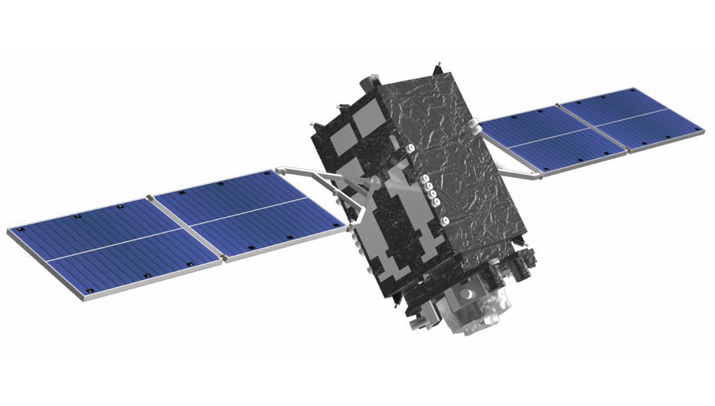
An important milestone in this collaboration was ESA’s role in supporting the In-Orbit Testing (IOT) activities for QZS-1R towards the end of 2021. The successful execution of these tests demonstrated the practical results of the ESA-JAXA partnership and further solidified the commitment of both agencies to enhance their capabilities for QZSS POD and associated products.
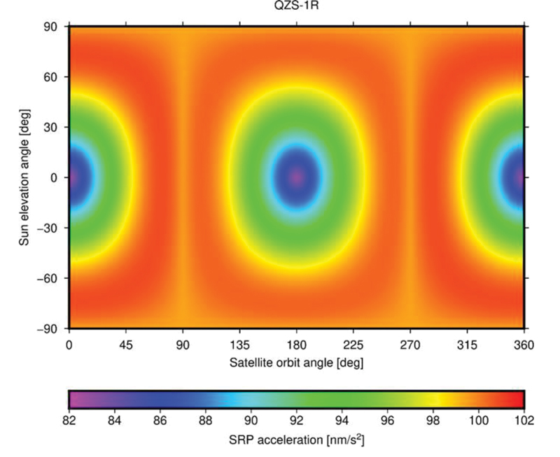
FIGURE 1 ESA’s Solar Radiation Pressure (SRP) model output in satellite-Sun frame.
The benefits of this collaboration extend beyond the agencies to the entire scientific community. Notable achievements include the revision of metadata for the QZSS constellation, such as the optical properties of the QZS-1 solar arrays, which have been refined and improved through shared expertise, while simultaneously releasing the satellite mass and attitude mode history in a machine-readable file format for easy access and adoption by the users.
To evaluate the spacecraft models and metadata for QZS-1R prior to their public release, ESA and JAXA conducted several comparative tests. Since both organizations use different software packages for satellite POD — ESA uses NAPEOS (Dow, Springer 2009, Enderle et al., 2019 and 2022) and JAXA uses MADOCA (Kawate et al., 2023) — their results can be considered as largely independent. One comparison involved the Solar Radiation Pressure (SRP) model results produced by both organizations. FIGURE 1 shows the accelerations in satellite-Sun frame computed by ESA’s SRP model. The comparison of the computed SRP accelerations in different reference frames, spacecraft-fixed and inertial, showed excellent agreement with differences of less than 0.1 nm/s².
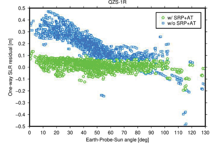
FIGURE 2 One-way Satellite Laser Ranging (SLR) range residuals calculated with respect to QZS- 1R orbits generated with (green) and without (blue) a-priori radiation force models and displayed as function of the Earth-Probe-Sun angle.
In addition, pseudo-range and carrier phase dual-frequency measurement data from 200 tracking stations of the International GNSS Service (IGS) network were used to generate precise QZS-1R satellite orbits and clock offsets on a day-to-day basis over a 12-month period spanning from January to December 2022. Comparison between ESA and JAXA solutions yielded a root-mean-square (RMS) agreement of 8.6 centimeters (orbit) and 0.21 nanoseconds (clock), respectively. Analysis of Satellite Laser Ranging (SLR) data from seven stations of the International Laser Ranging Service (ILRS) suggests a radial RMS accuracy of the generated orbital trajectories of about 4 cm. Without applying the analytical models for SRP and other non-gravitational perturbation forces, such as antenna thrust (AT), the RMS accuracy decreases by a factor of five (FIGURE 2).
In conclusion, the ESA-JAXA collaboration on Japanese Quasi-Zenith Satellite System POD has been a resounding success. Through this continuous and mutual support, performance cross-validation and knowledge sharing, significant improvements related to modeling and subsequently to POD accuracy could be achieved for ESA as well as for JAXA. Additionally, the global scientific community benefitted from this ESA/JAXA collaboration via improved QZSS POD products and validated metadata.
The UK has successfully tested quantum-based navigation systems in flight. The commercial trial was led by Infleqtion, a quantum technology company, and is designed to improve resilience against GPS jamming and spoofing.
Although GPS jamming typically does not affect an aircraft’s flight path, quantum-based positioning, navigation and timing (PNT) systems aim to provide accurate and resilient navigation, complementing existing satellite systems and offering uninterrupted operations for global air traffic.
Infleqtion, in collaboration with aerospace companies BAE Systems and QinetiQ, conducted the trials at MoD Boscombe Down in Wiltshire. Science Minister Andrew Griffith participated in the final test flight on May 9. The project has received nearly £8 million in government funding as part of the National Quantum Strategy, which seeks to establish the UK as a leader in quantum technology.
The test flights included two key quantum technologies: the compact Tiqker optical atomic clock and an ultra-cold-atom-based quantum system, both tested aboard QinetiQ’s RJ100 Airborne Technology Demonstrator. These technologies are part of developing a quantum inertial navigation system (Q-INS), which aims to provide precise and resilient navigation independent of traditional GNSS.
The successful flight trials are a step towards deploying quantum navigation systems on aircraft by 2030 as part of the UK’s National Quantum Strategy. The demonstrated potential of quantum technology in enhancing navigation security is an important development for future aerospace applications.
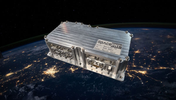
SpacePNT, a Swiss positioning, navigation and timing (PNT) solution provider for the new space satellite market, has completed in-orbit validation tests of its NaviLEO spaceborne GNSS receiver platform. The platform is designed to deliver decimeter-level positioning and nanosecond-level timing accuracy in low-Earth orbit (LEO) and signal reception sensitivity for GTO/GEO/moon missions. Using its unique and proprietary hardware and software technology, it can operate in real time.
After its successful deployment in LEO onboard its hosting orbital transfer vehicle, the D-Orbit ION OTV SCV-011 satellite, on June 13, 2023, Space PNT conducted a series of experiments to validate the key functionalities of the radiation-tolerant technology. This is done by demonstrating multiple modes of operation, including dual-antenna and full-in-flight reprogramming using FPGA image and application software.
Flight models have already been delivered to commercial and institutional partners for these missions, said SpacePNT co-founder and CEO, Cyril Botteron.
The upcoming second-generation hardware platform reuses the same key radiation-tolerant electronics components, designed for telecom constellations. It also implements new functions to serve additional markets such as software-defined radio platforms for telecom and radar applications.
The new space satellite market refers to companies such as SpacePNT, SpaceX and Blue Origin that are developing reusable rockets to drastically reduce the cost of access to space. The growth of satellite technology and new business models, such as satellite-based internet services, have created new opportunities for private companies.
MerlinTPS has partnered with Bluespec to address the need for GNSS augmentation and backup technology as satellites continue to face new challenges, including wartime contested space as well as increased costs to produce and maintain satellites.
Under the partnership, MerlinTPS will develop its platform to support the expansion of PNT security capabilities by using existing signals of opportunity on the ground designed to combat jamming and spoofing.
“With our verification and validation-centric RISC-V solutions, MerlinTPS can develop customized solutions in a matter of weeks, allowing it to deliver highly differentiated products with minimal project and schedule risk,” said Charlie Hauck, CEO of Bluespec.
By implementing Bluespec’s RISC-V processors in Field Programmable Gate Arrays (FPGAs), MerlinTPS can quickly modify, generate and load new code onto FPGAs. This allows for hardware reuse, avoiding the need to build custom hardware for each task.
However, MerlinTPS can easily make customizations to Bluespec’s RISC-V soft processor cores — adding custom instructions designed to accelerate specific workloads — when needed. MerlinTPS plans to add artificial intelligence (AI) capabilities to the platform.
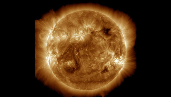
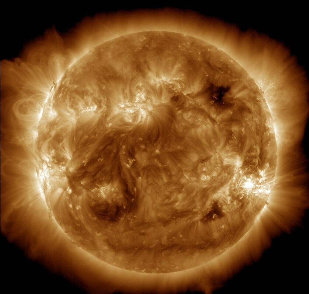
NASA’s Solar Dynamics Observatory captured this image of solar flares on May 11, 2024. The NOAA says there have been measurable effects and impacts from the geomagnetic storm. (Photo: Solar Dynamics Observatory)
Earth is experiencing a severe solar storm causing concern for those responsible for power grids, communication systems and satellites.
The National Oceanic and Atmospheric Administration (NOAA) has reported measurable effects and impacts from the geomagnetic storm that has been visible as aurora across vast swathes of the Northern Hemisphere. As of May 12, 2024, NOAA had seen no reports of major damage.
There has been some degradation and loss to communication systems that rely on high-frequency radio waves, NOAA told NPR, as well as some preliminary indications of irregularities in power systems.
“Simply put, the power grid operators have been busy since yesterday working to keep proper, regulated current flowing without disruption,” said Shawn Dahl, service coordinator for the Space Weather Prediction Center at NOAA.
“Satellite operators are also busy monitoring spacecraft health due to the S1-S2 storm taking place along with the severe-extreme geomagnetic storm that continues even now,” Dahl added, saying some GPS receivers have struggled to lock locations and offered incorrect positions.
As NOAA warned, the Earth has been experiencing a G5, or “extreme,” geomagnetic storm. It is the first G5 storm to hit the planet since 2003, when a similar event temporarily knocked out power in part of Sweden and damaged electrical transformers in South Africa.
As of May 13, NOAA’s Space Weather Prediction Center said that a G3, or “strong,” geomagnetic storm warning was in effect until 2 a.m. ET. While stronger storms are no longer likely and conditions are expected to “gradually wane” throughout the day, the center said in its forecast that moderate to strong geomagnetic storms are “likely” on May 13, as are minor storms on May 14.
The center also said that “solar activity is expected to be at high levels” with a possibility of more solar flares, or bursts of electromagnetic radiation from the sun.
The update came as another X-class solar flare was recorded. X-class flares are the strongest class of these solar bursts, and the latest was recorded as “moderate.”
Flares of this magnitude are not frequent,” the center said. “…Users of high frequency (HF) radio signals may experience temporary degradation or complete loss of signal on much of the sunlit side of Earth.”
Northern lights in unusual places
On May 12, people from all around the world shared photos of a dazzling display of the Northern Lights, which were visible in Russia, Scandinavia, the United Kingdom, continental Europe and some even reported seeing the aura as far south as Mallorca, Spain.
In the United States, the NOAA center shared that the storm-induced auroras were visible as far south as Northern California and Alabama.
The source of the solar storm is a cluster of sunspots on the sun’s surface that is 17 times the diameter of Earth. The spots are filled with tangled magnetic fields that can act as slingshots, throwing huge quantities of charged particles toward our planet. These events, known as coronal mass ejections, become more common during the peak of the Sun’s 11-year solar cycle.
While the storm has proven to be large, predicting the effects of such incidents can be difficult, Dahl said.
The world has grown more reliant on electronics and electrical systems. Depending on the orientation of the storm’s magnetic field, it could induce unexpected electrical currents in long-distance power lines. Those currents could cause safety systems to flip and trigger temporary power outages in some areas.
I took these photos near Ranfurly in Central Otago, New Zealand. Anyone can use them please spread far and wide. :-) https://t.co/NUWpLiqY2S
— Dr Andrew Dickson reform/ACC (@AndrewDickson13) May 10, 2024
The storm caused some navigational systems in tractors and other farming equipment to break down, suppliers and farmers told the New York Times.
Farmers have become dependent on equipment that utilizes GNSS and other navigation technology to help them plant more effectively — a practice known as precision agriculture. However, some of these operations in the Midwest, as well as in other parts of the United States and Canada, came to a temporary halt.
How it affects the ionosphere
The storm will also likely disrupt the ionosphere, a section of Earth’s atmosphere filled with charged particles. Some long-distance radio transmissions use the ionosphere to “bounce” signals around the globe, and those signals can be disrupted.
The particles may also refract and otherwise scramble GNSS signals, according to Rob Steenburgh, a space scientist with NOAA. Those effects can linger for a few days after the storm.
The storms can bring on ionospheric scintillation, which refers to rapid fluctuations in GNSS signal strength and phase due to localized irregularities in the electron density of the ionosphere resulting from solar activity. Scintillation adversely affects GNSS positioning, particularly around the geomagnetic equator after local sunset.
Similarly to Dahl, Steenburgh said that it is unclear just how bad the disruptions will be. While we still depend on GNSS, there are also more satellites in orbit. Moreover, the anomalies from the storm are constantly shifting through the ionosphere like ripples in a pool. “Outages, with any luck, should not be prolonged,” Steenburgh said.
An interview with Chuck Stoffer, director of business development and Eric Hughes, design engineer at UHU Technologies. Click here to read more from this cover story.
UHU 1000 seven-element antenna array on a U.S. Army Stryker vehicle. (Photo: UHU Technologies)
What is your company’s main differentiator in the market?
CS: Our big differentiator is our ability to detect and mitigate GPS spoofing. There are many products that perform jamming mitigation using multi-element antenna arrays, but they usually don’t operate below the noise floor on spoofers. Our big differentiator is the ability to go underneath the noise floor and locate the spoofing threat.
About 10 years ago, our founder, Jeff Sanders, got interested in the GPS spoofing problem. Jeff’s previous company, Eclipse Electronic Systems, was dedicated to building high-end signals intelligence (SIGINT) receivers and the entire design team here at UHU worked for Jeff there. We built high-end, multi-channel receivers, often used in direction finding applications. When we started UHU, Jeff’s idea was to use direction finding to validate the constellation using satellite position.
EH: Our system looks like an anti-jam system, which it is. However, it does a whole lot more than that. We use a controlled reception pattern antenna (CRPA) to do angle of arrival (AOA) measurements on each GPS satellite.
We know where each satellite is supposed to be, then we calculate where it actually is in the sky. If a satellite is in the right spot in the sky, then we know that we can trust it. If it’s not — and, especially, if multiple satellites are not in the right spot in the sky — then we know there’s a spoofer.
Once we’ve done that, we can take it a step further and perform non-adaptive spatial nulling, subtracting out the bad PRNs from the signals.
Often people look at our system and think, “Oh, it’s an anti-jam system.” Yes, we do anti-jam, just like any other vendor out there would do, and we do the traditional adaptive null steering techniques, so that if there’s a jammer in the environment, we will automatically null it spatially. However, those systems don’t handle spoofers, which, as Chuck was saying, are often below the noise floor. Anti-jam systems — which are using power minimization techniques — will not do anything for something that’s below the noise. In fact, they may inadvertently amplify the weak signal because they weren’t designed to process signals below the noise.
As far as outputs, we provide a spatially validated PNT solution, meaning that we only include satellites whose sky position has been validated. We also provide an RF output that can feed other GPS receivers, including M-Code. Our products have a built-in web-based GUI for visualization of the threat environment, and all system measurements can be sent over the network using multiple industry standard protocols.
To “precisely geo locate the source of GPS jamming or spoofing threats,” as one of your marketing materials says you can do, requires at least two bearings and the range.
EH:One of the nice things about our approach is that once we’ve identified a spoofer or a jammer, we can then tell you the line of bearing or the angle of arrival from the threat. Both of our products — the Northstar and the UHU1000 —also have a built-in event-based I/Q recorder and a GPS-disciplined oscillator that provides precision time. That gives us baseband data with precision timestamps anytime there’s a spoofing or jamming event. This is a standard feature that’s available right now.
You can take multiple systems, network them together, and, if they all have a common view of the interference event, use the provided lines of bearing and precision time-stamped I/Q data to perform geolocation based on AOA and/or time difference of arrival (TDOA). This is a separate appliance that’s in development.
In our next software release we are adding single-receiver, AOA-based geolocation. However, it requires motion. So, if you have a single UHH1000 in motion, you get a coarse geolocation automatically.
CS:We’ve already demonstrated our geolocation algorithms on real-world data and our geolocation appliance is on our roadmap. We’ve proven the technology, and now we’re productizing it.
This works very well for aerial platforms, because you get a lot of motion and many different looks at it. For ground-based applications, where the source could be many miles away and the AOA doesn’t really change much, it might not be as useful.
How it the threat evolving and how are you dealing with that?
EH: One of the advantages of our AOA-based approach is that it’s outside of the signal. It’s a physics thing that is very hard, if not impossible, to spoof. At government-sponsored events, every year they throw a new attack at the participants, often by modifying the signal in some novel way. Those are all great things that need to be tested, but we don’t care about any of that because all we’re doing is checking whether a satellite is in the right spot in the sky. If it’s in the right spot, we trust it. If it’s not, we don’t. Because of that, we’re well positioned to handle new threats.
CS: We individually track every GPS satellite signal that we detect, even the same repeating pseudorandom noise (PRN) code coming from a different AOA. Each PRN gets its own hardware-accelerated tracking loop with its own beamformer. Once we know which PRNs are valid satellites and which PRNs are spoofers, we group and demodulate them separately. We provide the spoofer PNT solutions to the user in real-time.
Are all your boxes multi-constellation?
EH:Today, we process L1 C/A and L2C. Since L1 C/A is the backbone of most GPS receivers, effective spoofing attacks always spoof L1 C/A, and that has been our focus area. Of course, we have a roadmap to do more.
To the extent that you are at liberty to tell me, who has your box? Who will have it?
Syntony GNSS has partnered with Keysight Technologies, an RF testing solutions manufacturer, to advance GNSS testing and simulation capabilities.
The collaboration centers on Keysight’s VXG advanced signal generator, which can generate thousands of simultaneous signals across all GNSS constellations and bands. It features time and phase synchronization for high fidelity and accuracy in simulation scenarios. This feature is particularly crucial for testing GNSS receivers under various conditions to ensure optimal performance in real-world scenarios.
The Syntony GNSS Simulator Constellator can mimic the complex dynamics of GNSS signals, providing a platform for testing and validating GNSS receivers. When combined with Keysight’s VXG, it serves as a comprehensive testing solution for all GNSS signals and scenarios.
The partnership aims to improve Controlled Reception Pattern Antenna (CRPA) testing. CRPA is pivotal in enhancing the resilience of GNSS receivers against interference and jamming to offer reliable operation even in adverse conditions. The combined solution from Syntony GNSS and Keysight offers a platform for testing CRPA systems to ensure they meet the stringent requirements of modern applications.
Telecommunications, among other sectors, relies heavily on precise timing information, typically derived from GNSS signals. The threat of jamming attacks, which can disrupt GPS time synchronization, poses a significant risk, potentially crippling communications and other dependent systems. The testing solutions emerging from this partnership provide a toolset for infrastructure managers to evaluate and enhance the resilience of their systems against such threats.
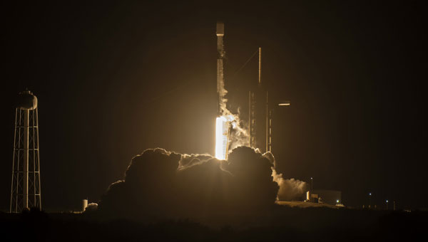
On April 27, 2024 the SpaceX Falcon 9 medium-lift launch vehicle launched into orbit Galileo satellites GM25 and FM27 from Kennedy Space Center in Florida. This was Falcon 9’s 20th and final launch.
The EU Agency for the Space Programme (EUSPA) confirmed in a statement that it is now in the Launch and Early Orbit Phase (LEOP) stage of the two new L12 Galileo satellites. They will join the current Galileo operational fleet in the upcoming months. The latest batch of Galileo satellites are being operated by EUSPA and the Galileo Service Operator for the Early Orbit Phase (EOP).
The EUSPA operations team, through its Galileo Service Operations provider, took over the satellite operations as the satellites were separated from the launch vehicle and their automated initialization sequence started. Telemetry has been successfully acquired, their solar panels deployed and the batteries are charging, bringing the satellites to what is called the Holding Point, according to EUSPA.
The EOP is a vital step in a space mission, running through the gradual activation and testing of platform satellite components, once in orbit. From the Galileo Control Centre in Oberpfaffenhofen, Germany, the dedicated LEOP team will navigate the satellites to their designated orbit within the coming days. Following rigorous in-orbit testing and commissioning, the satellites will integrate into Galileo’s operational constellation at 23,220 km.
The mission is a collaboration between the European Commission, which lead the management of Galileo; EUSPA, which manages operations and services with the support of the Galileo service operator (SpaceOpal); and the European Space Agency (ESA), which serves as the design authority, responsible for development.
GLONASS satellites traditionally use L1 and L2 frequency division multiple access (FDMA) signals. FDMA is characterized by a different transmit frequency for each satellite. Newer satellite generations also transmit an L3 code division multiple access (CDMA) signal. CDMA uses the same frequency but different ranging codes for individual satellites. The first GLONASS K2 satellite, with the space vehicle number R803, was launched in August 2023. It extends the range of CDMA signals to the L1 and L2 bands.
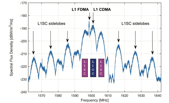
Figure 1. GLONASS K2 spectrum of the L1 frequency band. The different components of the L1 CDMA signal are indicated by colored boxes. L1SC: secured signal. L1OC: open service signal. (All figures provided by the authors)
Frequency spectra of R803, including these new signals, are shown in Figures 1 and 2. They were measured with the 30 m high-gain antenna of the German Space Operations Center (GSOC) in Weilheim, Germany, on Jan. 17, 2024. The largest and sharpest peak in the L1 band at 1,598.625 MHz originates from the 0.5 MHz binary phase-shift keying (BPSK) FDMA signal. The center peak of the L1 CDMA signal is located at 1,600.995 MHz. It is related to the L1 open service signal consisting of a data component (L1OCd) and a pilot component (L1OCp). L1OCd and L1OCp are combined by time-division multiplexing. The peaks that are ±5 MHz away from the L1 CDMA center frequency are introduced by the binary offset carrier (BOC) modulation of the secured L1SC signal. Prominent L1SC side lobes are visible ±15, ±25 and ±35 MHz offset from the center frequency. A quadrature phase-shift keying (QPSK) modulation is used to combine the L1OC and L1SC signals. The local minimum between 1,610 MHz and 1,614 MHz is caused by a notch filter onboard the satellite to protect radio astronomical observations of the Hydroxyl spectral line at 1,612 MHz.
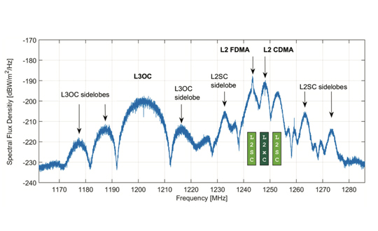
Figure 2. GLONASS K2 spectrum of the L2 and L3 frequency bands. The different components of the L2 CDMA signal are indicated by colored boxes. L2SC: secured signal. L2xC stands for the time multiplexed L2OCp and L2 CSI signal. (All figures provided by the authors)
The L2 CDMA signal is composed of a signal for service information (L2 CSI) and the pilot open service navigation signal (L2OCp). As for L1, these two signals are time-division multiplexed and combined with the secured L2SC signal by QPSK. The left main lobe of the L2SC signals coincides with the L2 FDMA center frequency of 1,243.375 MHz. Both, the L2 CSI, as well as the L2OCp signal, contribute to the peak at the L2 CDMA center frequency at 1,248.06 MHz. The L3 CDMA signal is composed of 10 MHz BPSK data (L3OCd) and pilot (L3OCp) components resulting in a broad peak at 1,202.025 MHz.
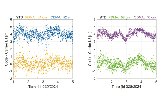
FDMA and CDMA signals of GLONASS R803 were tracked with a JAVAD TRE_3S receiver with a prototype firmware located at GSOC in Oberpfaffenhofen, Germany. Figure 3 shows the differences between pseudo range and carrier phase observations for the FDMA and CDMA signals in the L1 and L2 frequency bands. Long-term ionospheric effects were removed by a second-order polynomial. Thus, remaining effects include short-term ionospheric variations, multipath, and observation noise. The standard deviation of the code–carrier combination is, in general, at the half-meter level. Due to their advanced design, the CDMA signals show an improved performance by 18% for L1 and even 31% for L2 compared to the legacy FDMA signals.
Figure 3. Code – carrier for GLONASS R803 FDMA and CDMA signals: L1 (left) and L2 (right). A second order polynomial has been removed and the CDMA signals are shifted by 4 m. (All figures provided by the authors)
Further launches of L1 and L2 CDMA-capable GLONASS K2 satellites are planned for the upcoming years. A constellation of at least 12 satellites is expected for 2030. To guarantee backwards compatibility, these satellites will also transmit the L1 and L2 FDMA signals. Further improvements in positioning accuracy are expected due to improved satellite clocks and inter-satellite laser ranging.
Russian Space Systems (2016), GLONASS Interface Control Document: Code Division Multiple Access Open Service Navigation Signal in L1 frequency band. Russian Rocket and Space Engineering and Information Systems Corporation, Joint Stock Company.
Russian Space Systems (2016), GLONASS Interface Control Document: Code Division Multiple Access Open Service Navigation Signal in L2 frequency band. Russian Rocket and Space Engineering and Information Systems Corporation, Joint Stock Company.
Manufacturers
GNSS data used in this article were collected with a JAVAD TRE_3S receiver. The spectral overviews were captured with a Rohde & Schwarz FSQ26 signal analyzer.
 NAVSYS Corporation has secured a $4.4 million contract from the Rapid Architecture Prototyping and Integration Development (RAPID) Laboratory of the Air Force Research Laboratory (AFRL). The contract is part of AFRL’s Commercial Alternative Positioning, Navigation and Timing (PNT) for RAPID (CAPR) program, which aims to provide the Department of Defense improved access to reliable and resilient PNT services, particularly in situations where GPS is unavailable or compromised.