Category: GNSS

  • New type on the block: Generating high-precision orbits for GPS III satellites

    New type on the block: Generating high-precision orbits for GPS III satellites

    Read Richard Langley’s introduction to this article: Innovation Insights: Antennas and photons and orbits, oh my!


    To produce GNSS satellite orbit ephemerides and clock data with high precision and for all constellations, the Navigation Support Office of the European Space Agency’s European Space Operations Centre (ESA/ESOC) continually strives to keep up and improve its precise orbit determination (POD) strategies. As a result of these longstanding efforts, satellite dynamics modeling and GNSS measurement procedures have progressed significantly over the last few years, especially those developed for the European Galileo satellites. Because the accuracy of ESA/ESOC’s GNSS orbits has reached such a high level (about 1 to 3 centimeters), introducing a completely new type of GNSS satellite into the processing is not as easy as it used to be. New spacecraft models – the first and foremost being a model for a satellite’s response to solar radiation pressure (SRP) – are needed for the “newcomer” so that the quality of the overall multi-GNSS solution does not suffer. Just as important are spacecraft system parameters, or metadata, such as the location of the satellite antenna’s electrical phase center and the satellite attitude law.

    In this article, we show the efforts we have made at ESA to bring the quality of our orbit estimates for the GPS Block III satellites up to par with those for Galileo and the earlier GPS satellite blocks. We report on the results from on-ground and in-flight determinations of the Block III transmit antenna phase center characteristics up to 17 degrees from the antenna boresight direction. Moreover, we take advantage of the non-zero horizontal offsets of the transmit antenna from the spacecraft’s yaw axis to estimate the satellite yaw angle during Earth eclipse season and present a simple analytical formula for its calculation. Finally, we describe the development and validation of improved radiation force models for the Block III satellites.

    We start, however, by giving a brief overview of the GPS Block III program.

    GPS BLOCK III

    The U.S. Space Force GPS Block III (previously referred to as Block IIIA) is a series of 10 satellites being procured by the United States to bring new future capabilities to both military and civil positioning, navigation, and timing (PNT) users across the globe. Designed and manufactured by defense contractor Lockheed Martin (LM), the satellites are reported to deliver three times better accuracy, 500 times greater transmission power, and an eightfold enhancement in anti-jamming functionality over previous GPS satellite blocks. At ESA/ESOC, we are paying particular attention to this new tranche of satellites as they are the first to broadcast L1C, a new common signal interoperable with other GNSS, including Galileo.

    At the time of this writing, there are six GPS III space vehicles (SVs) in orbit. The first one – nicknamed “Vespucci,” in honor of Italian explorer Amerigo Vespucci – lifted off atop a SpaceX Falcon 9 rocket from Cape Canaveral Air Force Station, Florida, in December 2018, and entered service on January 13, 2020. An additional four SVs are expected to be launched soon, before moving on to an updated version called GPS IIIF (“F” for Follow On). The first Block IIIF satellite is projected to be available for launch in 2026.

    In view of the growing number of GPS III SVs in orbit, and soon to be joined by IIIFs, accurate spacecraft models and metadata information are becoming more and more important in order to maximize PNT accuracy.

    SATELLITE ANTENNA PHASE CENTER PARAMETERS

    GNSS signal measurements refer to the electrical phase center of the satellite transmitting antenna, which is neither a physical nor a stable point in space. The variation of the phase center location as a function of the direction of the emitted signal on a specific frequency is what we call the phase center variation (PCV). The mean phase center is usually defined as the point for which the phase of the signal shows the smallest (in a “least-squares” sense) PCV.

    Figure 1: Ground-calibrated GPS Block III transmit antenna phase center variations (PCVs). (All figures provided by the authors).
    Figure 1: Ground-calibrated GPS Block III transmit antenna phase center variations (PCVs). (All figures provided by the authors).

    The point of reference for describing the motion of a satellite, however, is typically the spacecraft center of mass (CoM). The difference between the position of the mean phase center and the CoM is what we typically refer to as the satellite’s antenna phase center offset (PCO). Both PCO and PCV parameters must be precisely known — from either a dedicated on-ground calibration or one performed in flight — so that we can tie our GNSS carrier-phase measurements consistently to the satellites’ CoM.

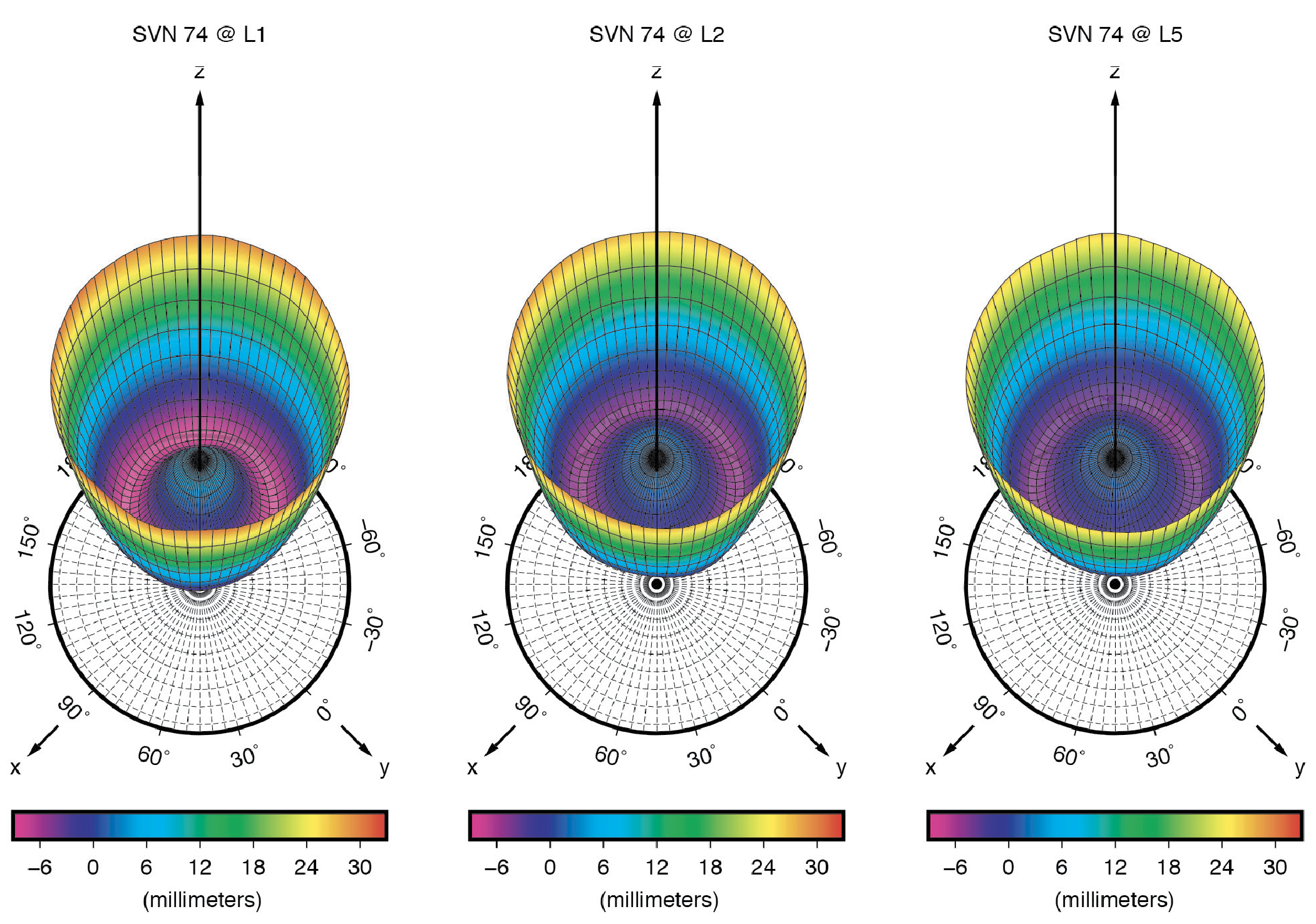
    On-Ground Calibrations. Like for previous GPS vehicles, the Block IIR and Block IIR-M satellites, LM has fully calibrated the GPS III transmit antennas prior to launch at their ground test facilities. Antenna offset parameters for all three carrier signals (L1, L2 and L5) were posted on the U.S. Coast Guard Navigation Center (NAVCEN) website (www.navcen.uscg.gov) shortly after each satellite launch. In December 2021, NAVCEN released the PCOs for SV number (SVN) 78, along with updates to the first four satellites (see Table 1). About ten months later, in October 2022, the antenna pattern for each satellite and signal frequency were published (see Figure 1).

    Table 1: Ground-calibrated GPS Block III transmit antenna PCOs in millimeters. (Image: GPS World staff)
    Table 1: Ground-calibrated GPS Block III transmit antenna PCOs in millimeters. (Image: GPS World staff)

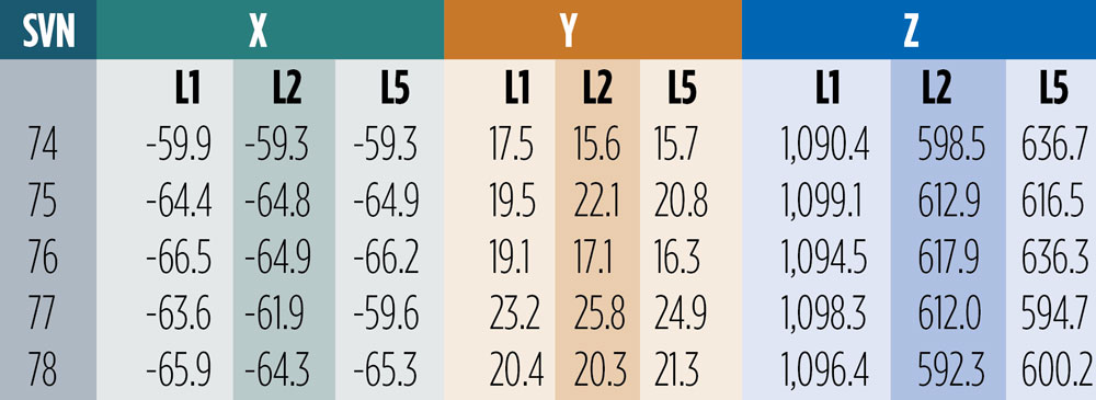
    The December 2021 offsets are referred to as predicted values at the end of year one on orbit. They differ from the previous ones by several centimeters in both vertical (Z) and horizontal (X and Y) directions. Particularly surprising are the X- and Y-PCOs, which were initially reported to be close to zero. The differences in the horizontal PCOs have generated uncertainty and debate, especially within the International GNSS Service (IGS) about which values to adopt for the new antenna model release (igs20.atx). Testing of the two different PCO datasets in our software demonstrated that the non-zero values as given in Table 1 are the significantly more accurate ones. We will return to this later in this article.

    Combined Ground- and Space-Based Tracking. In this part of this article, we discuss the combination of dual-frequency tracking data from geodetic-quality GPS receivers in low Earth orbit (LEO) with those from a global receiver network on the ground to determine the phase center parameters of the GPS Block III transmit antennas. The LEO-based measurements were taken by the GNSS receivers on board the ocean altimetry satellites Sentinel-6 Michael Freilich and Jason-3. The 1,336-km altitude of both of these missions enables the estimation of the GPS satellite antenna PCVs from 0 up to 17 degrees from boresight while GPS receivers on Earth can only see the satellites up to a maximum angle of 14 degrees. The 14-degree limit is also referred to as the GPS satellites’ edge of Earth (EoE) angle.

    For the modeling of the PCVs we follow the approach of the IGS using piece-wise linear functions of the boresight angle and constraining the PCV values to between 0 and 14 degrees to have zero mean. Furthermore, we employ fully normalized spherical harmonic expansions of degree 8 and order 5 to solve for the azimuth- and elevation-angle-dependent PCVs of the orbiting receiver antennas. The IGS standard antenna phase center corrections from igs20.atx are applied to all terrestrial receiver and GPS Block II transmit antennas.

    Figure 2: GPS Block III transmit antenna PCVs as a function of boresight angle. The gray shaded area indicates the angular range that is inaccessible from the ground but relevant to high altitude LEO missions such as Sentinel-6 Michael Freilich or Jason-3.
    Figure 2: GPS Block III transmit antenna PCVs as a function of boresight angle. The gray shaded area indicates the angular range that is inaccessible from the ground but relevant to high altitude LEO missions such as Sentinel-6 Michael Freilich or Jason-3.

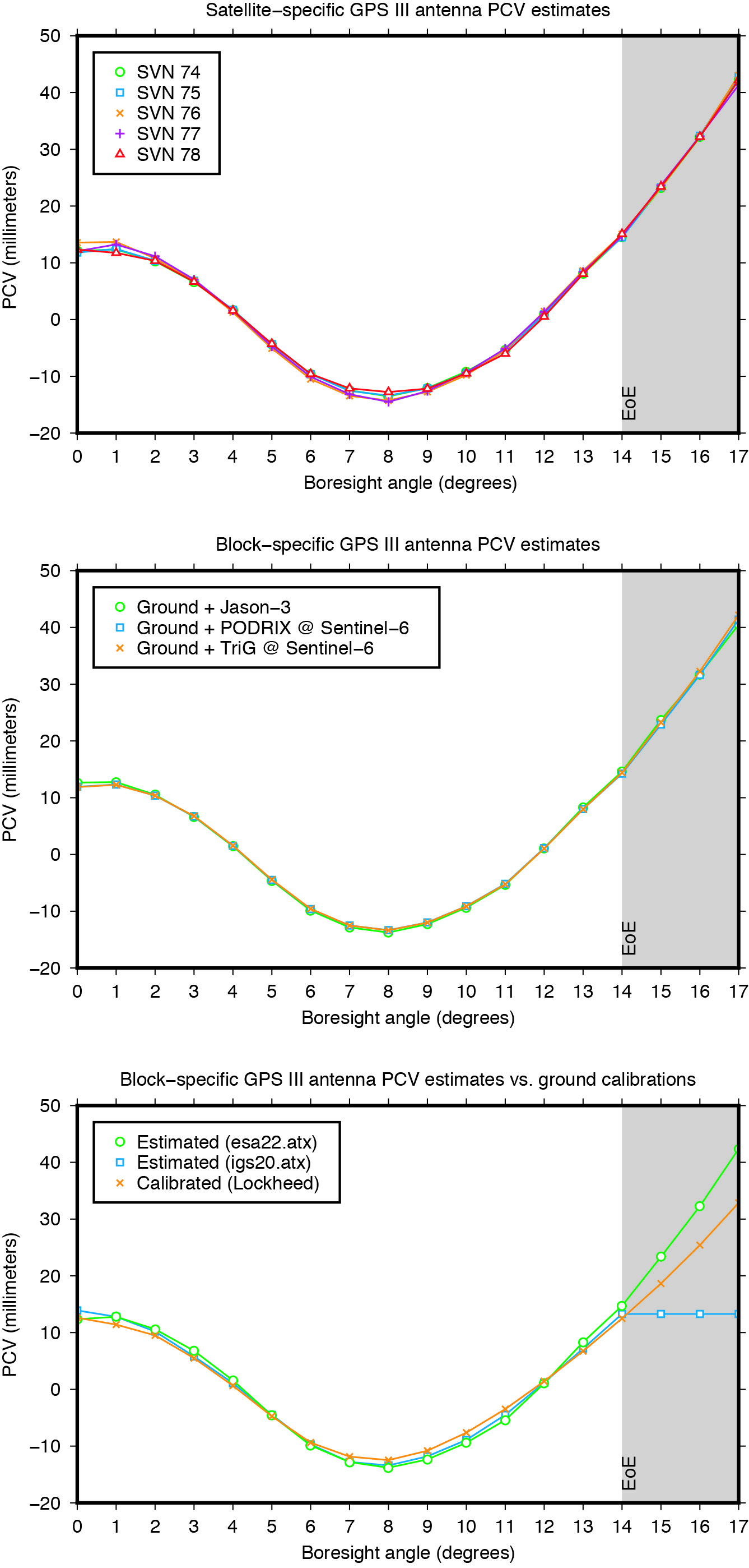
    The estimated Block III antenna PCVs are depicted in Figure 2. The estimates for the five individual antennas match each other to within 0.4 millimeters root-mean-square (RMS) (see Figure 2, top). The agreement among the PCVs that we get when processing the tracking data from each LEO receiver’s antenna separately is at the sub-millimeter level, too (see Figure 2, middle). Overall, the level of consistency suggests that the PCVs are of very good quality and that a block-specific representation is sufficient for precise applications. Comparison of the final block-specific PCV estimates against the values from the current IGS antenna model and from the ground calibrations shows strong agreement (RMS = 0.7 millimeters) between 0 and 14 degrees from boresight (see Figure 2, bottom). Beyond the 14-degree limit, the differences compared to the IGS standard are up to three centimeters, underlying the urgent need for an update of the igs20.atx file.

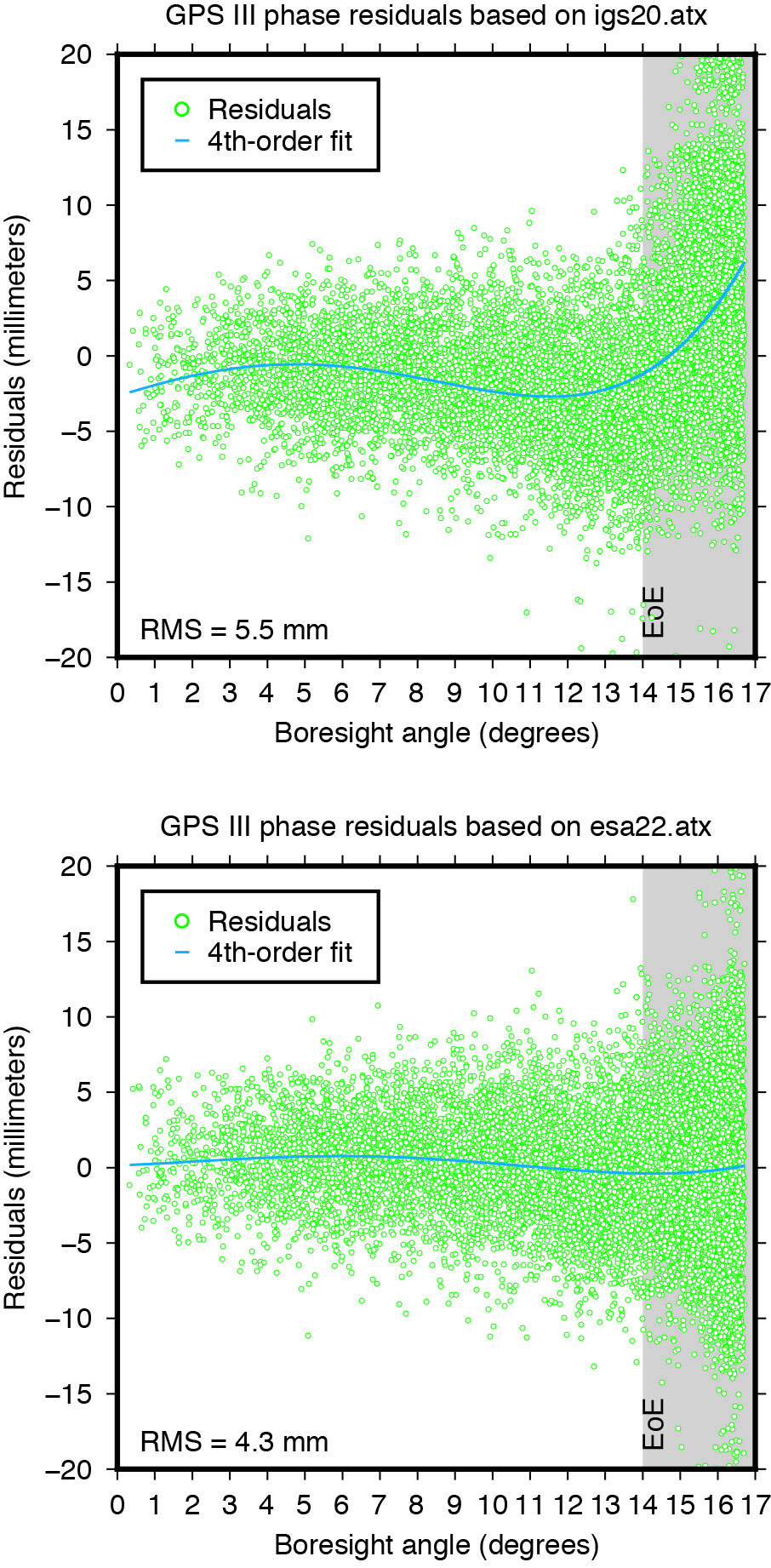
    Applying the extended PCV corrections as part of the POD process to the GPS LEO receiver data shows significant improvement in the post-fit carrier-phase residuals when compared to the PCV corrections from the IGS legacy model. It removes a previously existing boresight angle-dependent trend and leads to a more than 20% reduction in the computed residual RMS (see Figure 3).

    Figure 3: Post-fit residuals of GPS III carrier-phase data from Sentinel-6 Michael Rreilich when using igs20.atx (top) and esa22.atx (bottom), respectively.
    Figure 3: Post-fit residuals of GPS III carrier-phase data from Sentinel-6 Michael Freilich when using igs20.atx (top) and esa22.atx (bottom), respectively.

    YAW MODELING

    Figure 4: Yaw turn maneuver of GPS Block III satellite SVN 78 near orbit now (top) and orbit midnight (bottom), respectively.
    Figure 4: Yaw turn maneuver of GPS Block III satellite SVN 78 near orbit noon (top) and orbit midnight (bottom), respectively.

    GNSS satellites cannot follow an ideal yaw-steering whenever the Sun elevation angle relative to the orbital plane (the so-called beta angle) gets too low and the yaw rate required to keep the satellite solar panels pointing towards the Sun exceeds the maximum satellite yaw rate. The strategies on how GNSS satellites perform rate-limited yaw-steering are different for each type of spacecraft and only partly documented for public users. Continuous knowledge of GNSS spacecraft yaw attitude, however, is important for kinematic and dynamic reasons. Errors in yaw are known to affect the modeling of transmit antenna phase center’s position, carrier-phase wind-up, and radiation pressure forces. On the other hand, when the mean antenna phase center location is offset from the spacecraft’s Z-axis, the satellite yaw state can be estimated instantaneously from the tracking data of a global receiver network. The approach behind this is commonly referred to as “upside down” or “reverse kinematic precise point positioning” (RPP). The horizontal antenna offset vector can be viewed here as a kind of rotating lever arm whose length determines the accuracy of the yaw angle estimates. Since the Block III X-offset is just 7 centimeters, one should not expect the same RPP accuracy as for other GNSS satellites like those of the GPS IIF or GLONASS-M series, which have an X-offset that is six (GPS IIF) or even eight (GLONASS-M) times larger.

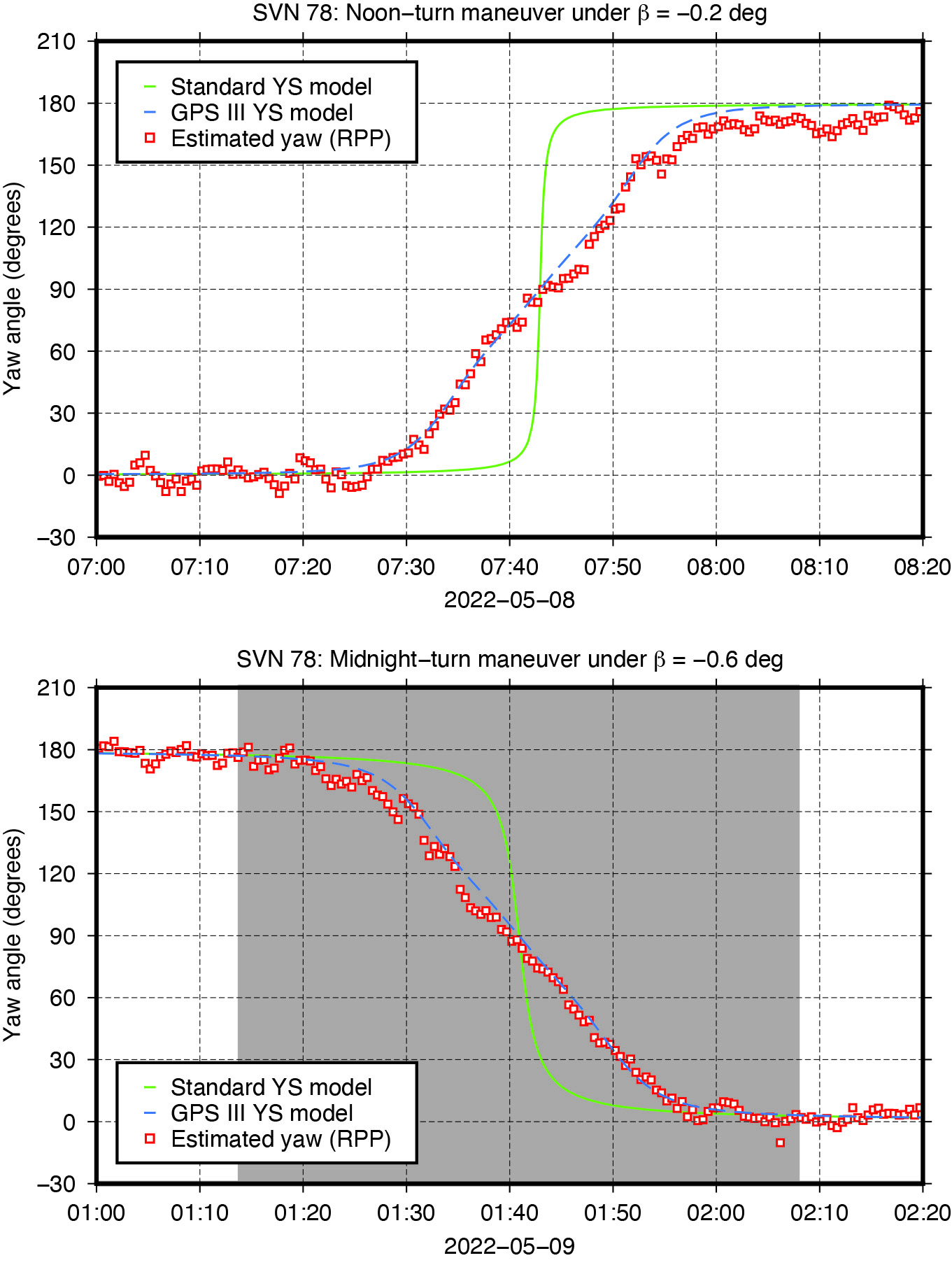
    Nonetheless, with more than three hundred ground stations, kinematic RPP works reasonably well even for GPS III as we can see from Figure 4, which shows the estimated yaw angle of SVN 78 while passing orbit noon and orbit midnight with a Sun elevation angle of almost zero degrees. The plots suggests that Block III satellites — unlike previous Block IIA and IIF SVs — perform their yaw slews near noon and near midnight in the same way and at the same yaw rate. In this respect, the yaw turn behavior is similar to that of the IIR/IIR-M satellites. However, with a maximum yaw rate of 0.10 degrees per second, the Block III satellites rotate only half as fast as those of the IIR/IIR-M family. What is also different is the start time of the yaw maneuver. As can be seen from Figure 4, the maneuver does not start when the required yaw rate exceeds the physical limit but already a couple of minutes before.

    The RPP analysis has led to the development of a simple yaw model for the Block III satellites. For a Sun elevation angle β below β0 = 4.780 degrees, the yaw angle can be approximated with an RMS accuracy of about 8 degrees by the following formula:Photo:
    whereasPhoto:

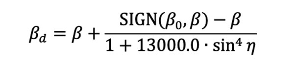
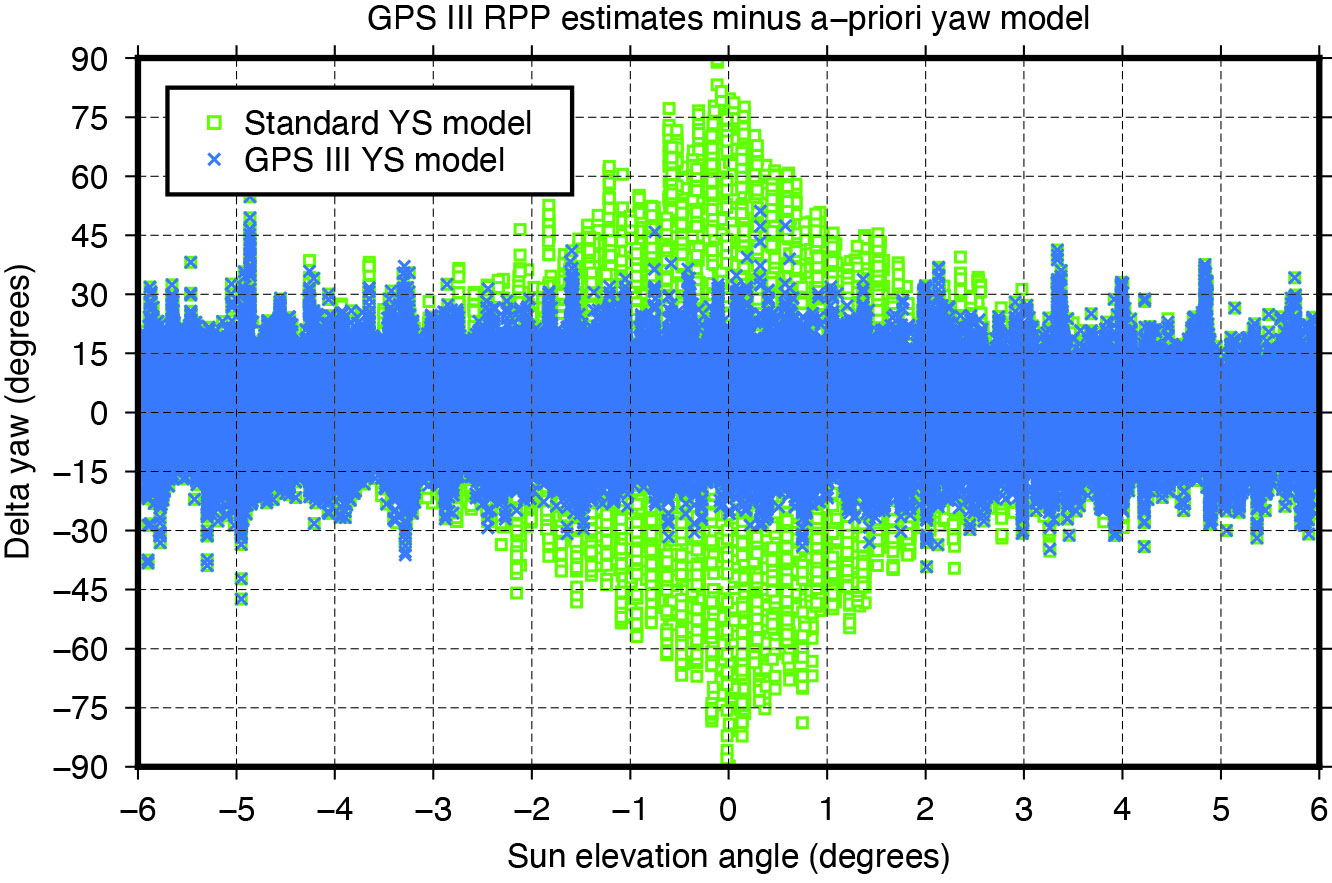
    is a modified Sun elevation angle, SIGN(β0, β) a FORTRAN function returning the value of β0 with the sign of β, and η is the satellite’s argument of latitude with respect to orbit midnight. The agreement between estimated and modelled yaw angles is illustrated in Figure 5.

    Figure 5: Differences between yaw angle estimates and yaw angle models.
    Figure 5: Differences between yaw angle estimates and yaw angle models.

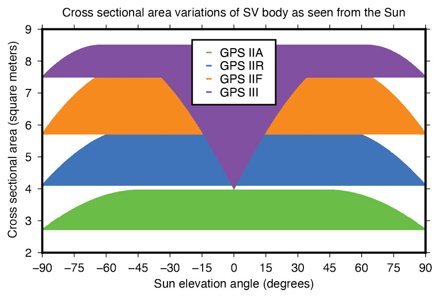
    Fourier Series for Radiation Force Modeling. The most critical component determining the shape of a GNSS satellite’s trajectory is SRP – the force caused by the impact of solar photons hitting the satellite’s surfaces. A satellite’s sensitivity to SRP can be characterized by the variation of the cross-sectional area to mass ratio (A/M) of the satellite body as it orbits Earth and the Sun. The greater the change in A/M, the higher the sensitivity. From this perspective, the Block III spacecraft can be considered the most sensitive in GPS history.

    Based upon LM’s tried-and-true A2100 bus, the satellite is much more elongated than previous generations. With an estimated size of 7.5 meters squared, the X-side is almost twice as large as the Z-side. Depending on the elevation angle of the Sun relative to the orbital plane, the body’s cross-sectional area exposed to sunlight varies between 4.0 and 8.5 meters squared (See Figure 6). With a nominal on-orbit weight of approximately 2,160 kilograms, this results in a change of A/M of 0.0021 meters squared per kilogram. For comparison, the corresponding values for the previous GPS SVs are 0.0015 (IIF), 0.0017 (IIR), and 0.0013 (IIA) meters squared per kilogram.

    Figure 6: Size of GPS satellite body’s cross-sectional area exposed to sunlight.
    Figure 6: Size of GPS satellite body’s cross-sectional area exposed to sunlight.

    Given the size and shape of Block III spacecraft, an appropriate radiation force model is considered mandatory to achieve the highest orbit accuracy possible. With that said, we empirically derived a set of background force models for the first five GPS III satellites. Our approach rests on dynamical long-arc (9-day) fitting to precise orbit data spanning up to three years and the following low-order Fourier functions of the Earth-spacecraft-Sun angle ε to represent the radiation force in the satellite body-fixed system:

    Photo:

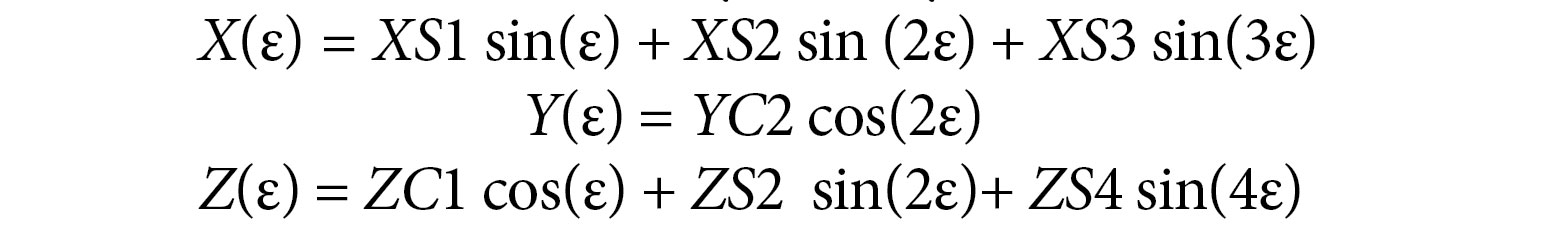
    The Fourier coefficients (XS1, XS2, XS3, YC2, ZC1, ZS2 and ZS4) are iteratively adjusted together with initial epoch state, a constant Y-axis bias, and 1‐cycle per revolution along‐track parameters to best fit the orbit data in a least-squares sense. All individual 9-day arc solutions are rigorously combined on a normal equations level to form a robust set of Fourier model coefficients for each satellite or group of satellites.

    ORBIT OVERLAP TESTS

    Figure 7: Impact of horizontal antenna PCOs and Fourier force model on day-boundary orbit overlap errors.
    Figure 7: Impact of horizontal antenna PCOs and Fourier force model on day-boundary orbit overlap errors.

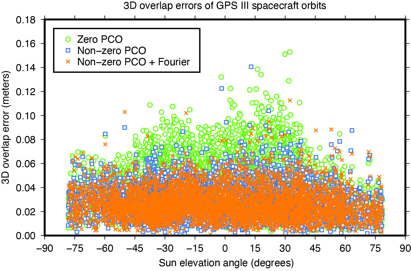
    To investigate the effect of the transmit antenna PCOs and the Fourier force models on the satellite orbits, we use our ESA/IGS processing strategy to generate dynamic 24-hour-arc solutions spanning January 2020 to December 2022, first with zero PCO and the non-zero horizontal offsets from Table 1 and no a-priori radiation force model, then with the non-zero offsets and the additional Fourier model in the background. The direct comparison of the generated orbits reveals significant differences for the Block III satellites of about 0.1 meters (3D).

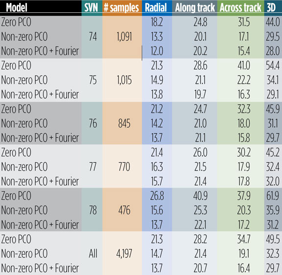
    To demonstrate the improved performance of the non-zero offsets and the Fourier model, we take the orbits for successive days and look at the midnight epoch where they overlap. The difference in the orbit position, subsequently referred to as “overlap error,” gives us a worst case estimate of the satellite orbit accuracy. Comparison of the overlap errors provides evidence that the Block III orbits are much more accurate when using the non-zero rather than the zero X and Y PCOs. The overall 3D overlap RMS reduces from 49.5 millimeters (with zero PCOs) down to 32.3 millimeters (with non-zero PCOs). Results for the Sun elevation regions below 45 degrees, in particular, show significant improvement (see Figure 7).

    Use of the Fourier model has additional positive impact on the overlaps. Comparing the orbits produced with and without the a-priori radiation force model, we see a decrease in the 3D overlap error RMS from 32.3 to 29.7 millimeters averaged over all satellites. The orbit component that benefits most from both the improved antenna phase and the advanced force modeling is the one normal to the satellite orbital plane (across track). The SVs improving the most are SVN 75 and SVN 78, though significant improvements can be seen for all other satellites too (see Table 2).

    Table 2: Day-boundary overlap RMS errors of GPS III spacecraft orbits in millimeters.
    Table 2: Day-boundary overlap RMS errors of GPS III spacecraft orbits in millimeters.

    EMPIRICAL PARAMETER ESTIMATES

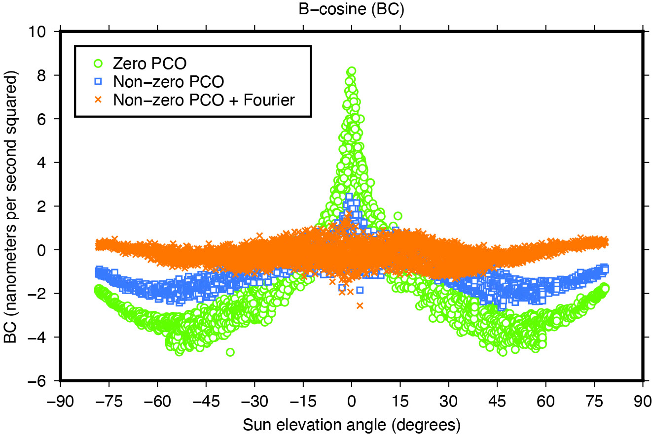
    Another means of assessing the quality of spacecraft models is the size and variability of the five-plus-three empirical dynamic radiation pressure parameters that we still estimate on a daily basis for each GNSS satellite in addition to its a-priori force model. Introducing the non-zero PCO and Fourier models into the POD turned out to reduce the size of the empirical parameters and their dependency on the satellite-Sun geometry to a great extent as the example in Figure 8 demonstrates.

    Figure 8: Impact of horizontal antenna PCOs and Fourier force model on empirical once-per-revolution acceleration term BC.
    Figure 8: Impact of horizontal antenna PCOs and Fourier force model on empirical once-per-revolution acceleration term BC.

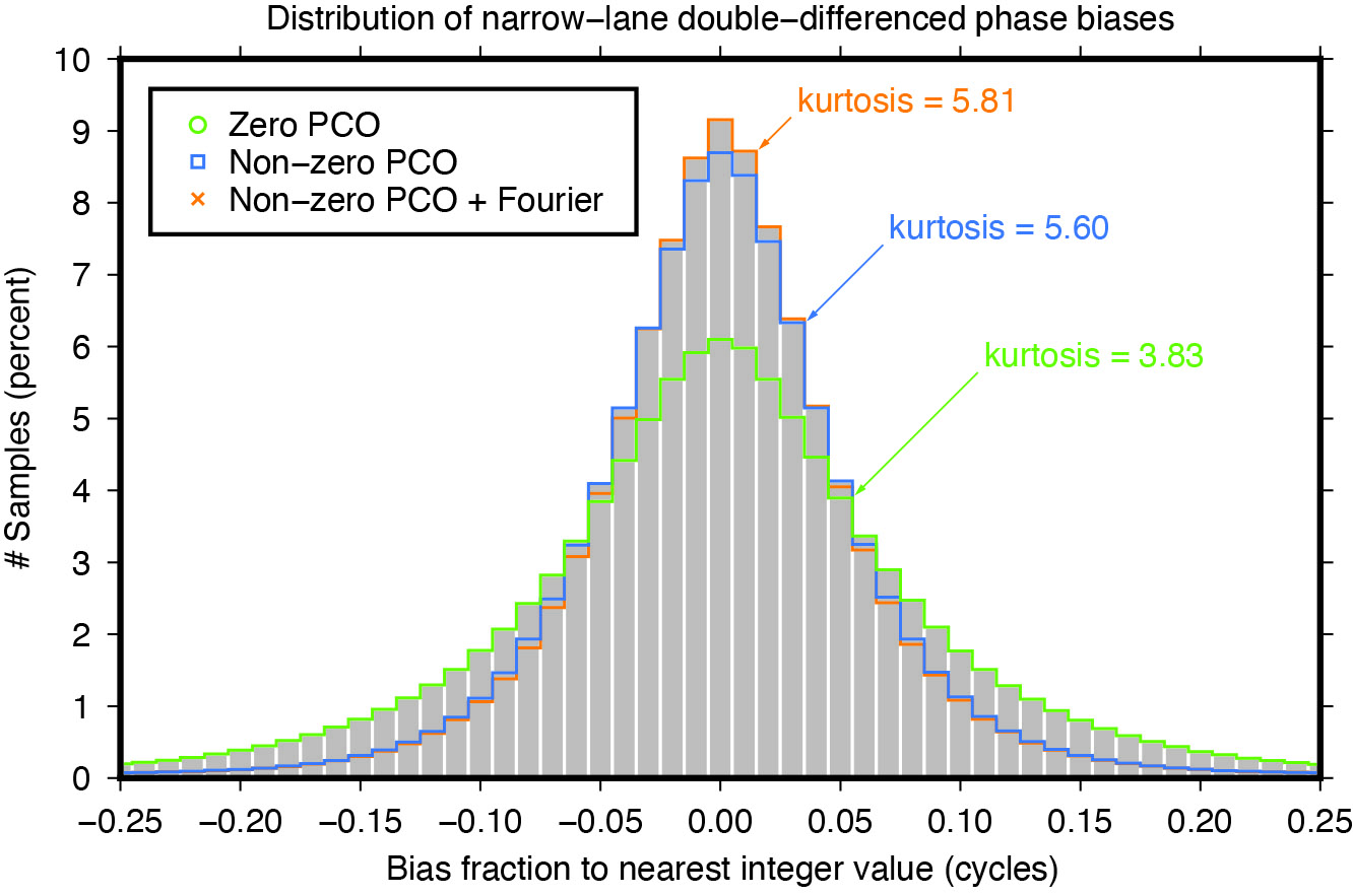
    NARROW-LANE AMBIGUITY FRACTIONALS

    Integer ambiguity resolution — that is, resolving the unknown cycle ambiguities of double-differenced carrier-phase data to integer values — is considered indispensable to GNSS satellite POD and commonly results in a factor of two improvement in orbit precision. Of particular importance is the narrow-lane ambiguity that results from combining the carrier-phase measurements from a pair of GNSS frequencies. One of the intermediate steps in the ambiguity resolution algorithm is the fixing of the double-differenced narrow-lane ambiguities to integer values. For reliable fixing, the fractional part of the difference between the integer and decimal (float) values should be as close as possible to zero and follow a symmetrical distribution. The “tailedness” of the distribution curve may be characterized by its kurtosis — the larger the kurtosis, the fewer values are in the tails of the distribution and the more peaked is the distribution. In other words, the larger the kurtosis, the closer the “fractionals” cluster around zero, the more ambiguities can be resolved with higher confidence, and the more accurate the resolved solution. Moreover, as satellite orbit and antenna phase center errors do not cancel out completely through double-differencing, the narrow-lane kurtosis may also be considered as an indicator for the accuracy of the satellite force and phase center models that were used. The results in Figure 9 show that the non-zero horizontal PCOs bring a major improvement and that the Fourier force model does give some additional benefit.

    Figure 9: Impact of horizontal antenna PCOs and Fourier force model on fractional part of double-differenced narrow-lane ambiguities.
    Figure 9: Impact of horizontal antenna PCOs and Fourier force model on fractional part of double-differenced narrow-lane ambiguities.

    CONCLUSIONS

    Adding a new GNSS satellite type to high-precision multi-GNSS solutions requires detailed knowledge and understanding of the satellite type. Key issues are the transmit antenna phase center parameters, the satellite’s attitude, and the radiation pressure forces acting on its surfaces.

    In this article, improved antenna phase center, attitude, and radiation pressure models for the current series of GPS Block III spacecraft have been developed using multiple years of in-flight orbit and tracking data. A number of internal metrics such as post-fit carrier-phase residuals, day-boundary orbit differences (overlaps), empirical acceleration parameters, and carrier phase ambiguity statistics have been used to gauge the models’ performances. Overall, the results underscore the importance of the models for GPS III orbit determination. This applies primarily to the radiation force and the antenna phase center model, or more precisely, the horizontal (X and Y) offsets of the phase center model whose existence has been neglected for years in the analysis of GPS III data.

    Comparison of the overlap statistics suggest that orbits generated based upon updated (non-zero) phase center corrections and ESA/ESOC’s new (Fourier-based) radiation pressure model in the background are better by almost a factor of two. The average overlap RMS errors calculated across all current Block III SVs and for each orbital component (radial, along track and across track) dropped from 21 , 28 and 35 millimeters down to 14, 21 and 16 millimeters, respectively.

    More relevant when it comes to processing GPS data recorded on board low-flying satellites such as Sentinel-6 Michael Freilich or Jason-3, is the extension of the current IGS Block III antenna PCV model beyond a 14-degree boresight angle. After applying the extended PCV corrections, we reduced Block III carrier-phase residuals by 20% with no or few systematic signatures remaining, unlike the residuals produced with the current IGS antenna model. The IGS is strongly encouraged to adopt the Block III PCV extension into their antenna model to continue to support GPS-based POD of low-Earth-orbiting satellites.

    For further details on ESA/ESOC’s solar radiation pressure modeling approach, see our paper “GPS III Radiation Force Modeling” presented at the IGS 2022 Virtual Workshop: click here.


    FLORIAN DILSSNER is a satellite navigation engineer in the Navigation Support Office at the European Space Operations Centre (ESOC) of the European Space Agency (ESA), Darmstadt, Germany. He earned his Dipl.-Ing. and Dr.- Ing. degrees in geodesy from the University of Hannover, Germany.

    TIM SPRINGER has been working for the Navigation Support Office at ESA/ESOC since 2004. He received his Ph.D. in physics from the Astronomical Institute of the University of Bern in 1999.

    FRANCESCO GINI is a satellite navigation engineer in the Navigation Support Office at ESA/ESOC. He received his Ph.D. in astronautics and space sciences from the Centro di Ateneo di Studi e Attività Spaziali at the University of Padova in 2014.

    ERIK SCHÖNEMANN is a satellite navigation engineer in the Navigation Support Office at ESA/ESOC. He earned his Dipl.-Ing. and Dr.- Ing. degrees in geodesy from the University of Darmstadt, Germany.

    WERNER ENDERLE is head of the Navigation Support Office at ESA/ESOC. He holds a doctoral degree in aerospace engineering from the Technical University of Berlin, Germany.

  • Singular XYZ launches GNSS receiver with network RTK rover

    Singular XYZ launches GNSS receiver with network RTK rover

    Singular XYZ has released the Sfaira One GNSS receiver. The portable size, centimeter-accurate receiver provides users with an entry-level network real time kinematic (RTK) rover.

    Sfaira One is equipped with a GNSS module with 1,408 channels for GPS, BDS, GLONASS, Galileo and QZSS tracking — providing centimeter positioning in harsh environments. It also features advanced RTK and an anti-interference algorithm.

    The GNSS receiver connects via Bluetooth and can be configured to conduct surveying tasks on a smartphone. Additionally, Sfaira One supports SingularPad and SingularSurv software and is also compatible with mainstream field survey or GIS software.

    Sfaira One is IP65 dustproof and waterproof, which makes the receiver suitable for all weather conditions. It has a 4,800 mAh battery life with 16 hours working time and type-C interface that can be charged on-the-go with power bank.

    The Sfaira One GNSS receivers are online at SingularXYZ’s website and are available now.

  • EU court dismisses Galileo satellite contract complaint

    EU court dismisses Galileo satellite contract complaint

    Credit: ESA
    Credit: ESA

    On April 26, the European Union Court of Justice dismissed a complaint from OHB System regarding a contract awarded to Thales and Airbus to supply satellites for the Galileo program, reported Reuters. OHB System supplied most of Galileo’s operating satellites.

    In 2021, the European Commission rejected OHB System’s bid to supply the next-generation Galileo satellites and selected Airbus Defense and Space and Thales Alenia Space Italia. This follows a 2018 tender by the European Space Agency for next-generation Galileo satellites.

    OHB System requested the European Commission and the ESA suspend the tender after its former chief operating officer was hired by Airbus and to exclude Airbus from the tender. This was rejected in January 2021.

  • NTS-3 satellite to launch this year

    NTS-3 satellite to launch this year

    The Navigation Technology Satellite–3 (NTS-3) — designed, built and tested by L3Harris — is on track to launch this year. The experimental satellite aims to shape the future of U.S. positioning, navigation and timing capabilities and to help U.S. forces to operate in GPS-denied environments and areas prone to spoofing.

    NTS-3 minimizes the impacts of GPS jamming through rapidly reprogrammable signal waveforms, frequency agility and increased signal strength. Its embedded software and firmware are reprogrammable on-orbit.

    When paired with reprogrammable receivers, the U.S. Air Force and U.S. Space Force can react in real time as threats evolve on the battlefield. In addition, NTS-3 has enhanced processors to support more complex signals.

    In January, L3Harris delivered the NTS-3 vehicle to Kirtland Air Force Base, New Mexico, to prepare the satellite for launch. The Air Force Research Laboratory and L3Harris are working together to complete space vehicle testing, launch vehicle integration and enterprise integration to confirm compatibility between the control segment, ground receivers and the satellite vehicle.

    NTS-3 is scheduled to launch later this year aboard United Launch Alliance’s Vulcan Centaur rocket. Once launched, NTS-3 will remain in a near-geosynchronous orbit for an inaugural year of testing.

  • Seen & Heard: Tracking pythons and wild camels

    Seen & Heard: Tracking pythons and wild camels

    “Seen & Heard” is a monthly feature of GPS World magazine, traveling the world to capture interesting and unusual news stories involving the GNSS/PNT industry.


    Image: Apple
    Image: Apple

    Apple Products Meet Accuracy with GPS

    Apple launched the Ultra Watch, which contains a dual-frequency GPS antenna that can receive L5 signals, as well as the iPhone 14, which features a dual-band GPS receiver combining the L1 and L5 signals. The company is also harnessing signals from more than 70 satellites to boost the accuracy of its services such as SOS alerts and alerting emergency responders, per The National News. The dual-frequency abilities of the new products provide accurate location for calculating distance, pace and routes. The L5 signals also are a critical component of Apple’s health and safety features, providing more accuracy than in previous products.


    Image: dwi septiyana/iStock/Getty Images Plus/Getty Images
    Image: dwi septiyana/iStock/Getty Images Plus/Getty Images

    Collar Accidently Tracks Python

    Wildlife researchers in Key Largo, Florida, accidently discovered a way to locate and eradicate invasive Burmese pythons, per WFLA News Channel 8. The team of researchers were observing racoons and possums that were fitted with tracking collars to note their behavior. After months of observation, a possum collar sent a mortality signal due to lack of movement. To the researchers’ surprise, the collar then started moving again. They later discovered the possum had been eaten by a python. While this was not the intent of the team’s research, they proved this could be an effective way to lower the increasing population of the invasive python species.


    Image: Pavliha/ iStock/Getty Images Plus/Getty Images
    Image: Pavliha/ iStock/Getty Images Plus/Getty Images

    Remote-Sensing Finds Wild Camels

    Scientist Liu Shaochuang and his team have used satellite remote-sensing technology to study and track wild camels. Shaochuang studies the interrelationship between endangered animals and their environments, which may help protect the species against climate change. To track a camel, Shaochuang attaches a GNSS-enabled collar, which transmits the camel’s location every day. The short message function is provided by China’s BeiDou satellite system, which transmits and receives signals in real time. Based on the data, Shaochuang and his team can observe migratory paths, living environments and possible threats.


    Image: Screenshot of CNN video
    Image: Screenshot of CNN video

    Former South Carolina Attorney Convicted with Location Data

    On March 3, Alex Murdaugh was convicted of killing his son Paul Murdaugh and wife Maggie Murdaugh. With limited evidence, the prosecution used a phone video and vehicle navigation data to prove Alex’s guilt. During the trial, Alex claimed he was visiting his mother during the time the murders took place. However, General Motors OnStar data accessed by investigators from his Chevrolet Suburban contradicted the alibi, putting Alex at the scene of the crime during the time of the murders. Plus, in a smartphone video taken by Paul that night, Alex’s voice could be heard, placing him at the scene.

  • Who are the GPS operators? What do they do?

    Who are the GPS operators? What do they do?

    Lt. Col. Robert O. wray commands the 2nd Space Operations Squadron (2 SOPS), which operates GPS around the clock supplemented by members of the 19th Space Operations Squadron (19 SOPS). (Credit: Dennis Rogers)
    Lt. Col. Robert O. wray commands the 2nd Space Operations Squadron (2 SOPS), which operates GPS around the clock supplemented by members of the 19th Space Operations Squadron (19 SOPS). (Credit: U.S. Space Force photo by Dennis Rogers)

    Exclusive GPS World interview with the commander of the unit that operates the GPS constellation

    The entire Global Positioning System constellation comprised of 38 satellites — with its billions of users and myriad military, commercial, consumer and scientific applications — is controlled from one room in a gray office building on a small military base about nine miles east of Colorado Springs, Colorado. The base is Schriever Space Force Base (SFB) and the room is the “operations floor” of the GPS Master Control Station (MCS). It is staffed by members of the 2nd Space Operations Squadron (2 SOPS), an active-duty unit of the U.S. Space Force, supplemented by members of the 19th Space Operations Squadron (19 SOPS), a unit of the U.S. Air Force Reserve. The two squadrons are known collectively as “Team Blackjack.

    Lt. Col. Robert O. Wray is the commander of 2 SOPS and of those 19 SOPS members assigned to the MCS. On March 16, at Schriever SFB, Wray spoke at length with GPS World’s editor-in-chief, Matteo Luccio, about the training and duties of his team members, the challenges they face, and what brought him to his current assignment. He then gave Luccio a tour of the MCS and introduced him to each of the 10 people on duty. At any given time, eight of these operators are military personnel and two are civilian contractors. They receive feeds from a worldwide network of monitor stations and ground antennas, including telemetry from the satellites, that enable them to precisely monitor the satellites’ orbits and the state of their systems. The operators upload data and commands to the satellites around the clock to keep the constellation fine-tuned and respond to changing circumstances.

    An abridged version of the interview will appear in the May issue of GPS World. A longer version will appear here on May 1.

  • Topcon invests in DDK Positioning

    Topcon invests in DDK Positioning


    Credit: DDK Positioning
    Credit: DDK Positioning

    Topcon Positioning Systems has made an investment in DDK Positioning, a UK-based GNSS receiver and precise point positioning correction services company. DDK Positioning delivers services over the Iridium network to provide global precision positioning services that can augment GNSS constellations enhancing accuracy for critical industrial applications.

    “With the expansion and growing success of this business, specifically in the marine sector, a closer cooperation will ensure optimal integration for the highest possible accuracies and performance in the most demanding applications,” Ian Stilgoe, vice president of Emerging Business at Topcon, said.

    “This partnership provides an extraordinary opportunity for our two companies to work together in pursuit of our shared ambition — providing a robust, resilient and truly unique GNSS positioning service,” Kevin Gaffney, CEO of DDK Positioning, stated.

    Terms of the investment are not being disclosed.

  • Vast coalition seeks reversal of Ligado Order

    Vast coalition seeks reversal of Ligado Order

    Credit: YinYang/E+/Getty Images
    Credit: YinYang/E+/Getty Images

    The same 91 signers also sent an identical letter to President Biden.

     April 24, 2023 

    Dear Senators and Members of Congress:

    Last year, many of the undersigned wrote in reflection of the unprecedented opposition to the Federal Communications Commission’s (FCC’s) Ligado Order (1) across the vast federal and commercial user base of Global Positioning System (GPS), satellite communications and weather forecasting services. Three years after adoption of the Order, as eight petitions for reconsideration remain pending, (2) we again urge you to work together with the FCC to stay and ultimately set aside the Order. (3) Critically, this is now necessitated by the crucial, previously unavailable information that was produced at the direction of Congress: the independent technical review undertaken by the National Academies of Sciences, Engineering, and Medicine (NAS) (4) analyzing the potential interference issues related to the Ligado Order.

    We greatly appreciate your administration’s opposition to the Ligado Order and commitment that the National Telecommunications and Information Administration (NTIA), on behalf of the executive branch, will continue to actively pursue its petition for reconsideration of the Order. (5) As you know, the pending petitions for reconsideration convincingly demonstrate that the Ligado Order is legally and factually deficient. In the pending petitions, parties showed that the Ligado Order is fundamentally flawed, incompatible with the FCC’s rules and inadequate in protecting incumbent services from the harmful interference from Ligado’s proposed operations. This substantial documentation, among many other concerns from federal and commercial users, resulted in Congress enacting bipartisan legislation in consecutive years after the FCC’s adoption of the Ligado Order, mandating NAS’s independent technical review and requiring the Department of Defense (DoD) to brief federal representatives across the government “at the highest level of classification” on the potential for widespread harm from Ligado’s proposed terrestrial operations. (6) On this basis alone, the FCC should stay the Order in an acknowledgement that it clearly did not account for the full, real-world risk of harm associated with a nationwide terrestrial deployment in the L-band.

    While the pending petitions have a strong likelihood of success on their own merits, the FCC’s rules and the public interest now require the FCC to reconsider the Order in response to the extensive analysis in the NAS Report. (7) This new, previously unavailable information presented in the Congressionally-mandated independent technical review confirms that Ligado’s proposed terrestrial operations would cause harmful interference (8) at significant ranges to incumbent L-band services across a broad range of deployment scenarios. This is consistent with the well-supported and robustly documented analyses and determinations of the federal government, (9) including fourteen federal agencies and departments, (10) and commercial parties (11) alike. Importantly, as concisely stated by DoD and detailed in the NAS Report, “[t]he terrestrial network authorized by [the Ligado Order] will create unacceptable harmful interference for DoD missions. The mitigation techniques and other regulatory provision [sic] in [the Ligado Order] are insufficient to protect national security missions.”(12)

    The unequivocal conclusions of the NAS Report constitute the exact type of previously unavailable information that the FCC’s rules (13) dictate must be addressed on reconsideration. Indeed, NTIA stated on behalf of the executive branch that the NAS Report “offers the [FCC] an important opportunity to reconsider Ligado’s Authorization.”(14) We therefore urge you to work with the FCC to address the harm from Ligado’s proposed terrestrial network to critical GPS, satellite communications, and weather forecasting services by staying the Order, addressing the previously unavailable information contained in the NAS Report, and resolving the pending petitions for reconsideration.

    Sincerely,

    AccuWeather, Inc.

    Aerospace Industries Association

    Agricultural Retailers Association

    Airborne Public Safety Association

    Aircraft Electronics Association

    Aircraft Owners and Pilots Association

    Airlines for America

    Alabama Agricultural Aviation Association

    ALERT Users Group

    Allied Pilots Association

    Air Line Pilots Association, International

    American Geophysical Union

    American Meteorological Society

    American Rental Association

    American Road & Transportation Builders Association

    American Weather and Climate Industry Association

    Arizona Agricultural Aviation Association

    Arkansas Agricultural Aviation Association

    Associated Equipment Distributors

    Association for Uncrewed Vehicle Systems International

    Association of Aerial Applicators Washington

    Association of Equipment Manufacturers

    Association of Marina Industries

    Association of Montana Aerial Applicators

    Aviation Spectrum Resources, Inc.

    BoatU.S.

    California Agricultural Aircraft Association

    Cargo Airline Association

    CNH Industrial

    Coalition of Airline Pilots Associations

    CoBank

    Colorado Agricultural Aviation Association

    EarthScope Consortium

    Florida Agricultural Aviation Association

    General Aviation Manufacturers Association

    GeoOptics, Inc.

    George Washington University

    Georgia Agricultural Aviation Association

    Helicopter Association International

    Idaho Agricultural Aviation Association

    Illinois Agricultural Aviation Association

    Indiana Agricultural Aviation Association

    International Air Transport Association

    Iowa Agricultural Aviation Association

    Iridium Communications Inc.

    Kansas Agricultural Aviation Association

    Land Improvement Contractors of America

    Lockheed Martin Corporation

    Louisiana Agricultural Aviation Association

    Marine Retailers Association of the Americas

    Michigan Agricultural Aviation Association

    Microcom Environmental

    Minnesota Agricultural Aircraft Association

    Mississippi Agricultural Aviation Association

    Missouri Agricultural Aviation Association

    Narayan Strategy

    National Agricultural Aviation Association

    National Air Carrier Association

    National Business Aviation Association

    National Cotton Council

    National Society of Professional Surveyors

    National Weather Association

    Nebraska Aviation Trades Association

    NetJets Association of Shared Aircraft Pilots

    New Mexico Agricultural Aviation Association

    North Carolina Agricultural Aviation Association

    North Dakota Agricultural Aviation Association

    Northeast Agricultural Aviation Association

    Ohio Agricultural Aviation Association

    Oklahoma Agricultural Aviation Association

    Oregon Agricultural Aviation Association

    Pacific Northwest Aerial Applicators Alliance

    PlanetiQ

    Recreational Boaters of California

    Resilient Navigation and Timing Foundation

    Seafarers International Union

    South Dakota Aviation Association

    Southeast Aero Cultural Fair

    Space Science and Engineering Center at the University of Wisconsin-Madison

    Subsurface Utility Engineering Association

    Tennessee Aerial Applicators Association

    Texas Agricultural Aviation Association

    The Airo Group, Inc.

    The Semaphore Group

    Trimble Inc.

    U.S. Geospatial Executives Organization

    University Corporation for Atmospheric Research

    USA Rice

    Vertical Flight Society

    Westwind Helicopters

    Wisconsin Agricultural Aviation Association


    (1) Ligado Amendment to License Modification Applications, IBFS File Nos. SES-MOD-20151231-00981, SAT-MOD-20151231-00090, and SAT-MOD-20151231-00091, Order and Authorization, 35 FCC Rcd 3772 (2020) (“Ligado Order” or “Order”).

    (2) More than twenty parties in total signed petitions for reconsideration of the Ligado Order and all of these petitions remain pending before the FCC. See Petitions for Reconsideration of the National Telecommunications and Information Administration; the Air Line Pilots Association, International; the American Road & Transportation Builders Association, the American Farm Bureau Federation, and the Association of Equipment Manufacturers; the Joint Aviation Petitioners; Iridium Communications Inc., Flyht Aerospace Solutions Ltd., Aireon LLC, and Skytrac Systems Ltd.; Lockheed Martin Corporation; Trimble Inc.; and the Resilient Navigation and Timing Foundation, IB Docket Nos. 11-109 & 12-340 (all filed on or about May 22, 2020). The ten “Joint Aviation Petitioners” consist of the Aerospace Industries Association, the Aircraft Owners and Pilots Association, Airlines for America, Aviation Spectrum Resources, Inc., the Cargo Airline Association, the General Aviation Manufacturers Association, the Helicopter Association International, the International Air Transport Association, the National Air Transportation Association and the National Business Aviation Association.

    (3) The Commission should also not proceed with any companion rulemakings causing harmful interference to weather forecasting and hydrology services that could result in Ligado deployments, particularly in light of the analysis and recommendations presented in the “Spectrum Pipeline Reallocation 1675–1680 MHz Engineering Study (SPRES) Program Report. See Allocation and Service Rules for the 1675-1680 MHz Band, Notice of Proposed Rulemaking, 34 FCC Rcd 3352 (2019); U.S. Department of Commerce. National Oceanic and Atmospheric Administration. National Environmental Satellite Data Information Service. Spectrum Pipeline Reallocation 1675–1680 MHz Engineering Study (SPRES) Program Report. Silver Spring, MD: NESDIS, October 2020 (public release August 2022).

    (4) National Academies of Sciences, Engineering, and Medicine, Analysis of Potential Interference Issues Related to FCC Order 20-48 (2022), https://doi.org/10.17226/26611 (“NAS Report”).

    (5) Letter from Gina Raimondo, Secretary of Commerce, U.S. Dept. of Commerce, to The Honorable James M. Inhofe, ranking member, U.S. Senate Committee on Armed Services (June 22, 2021) (reiterating the NTIA’s position opposing the Ligado Order).

    (6) William M. (Mac) Thornberry National Defense Authorization Act (“NDAA”) for Fiscal Year 2021, Pub. L. 116-283, 134 Stat. 4074 § 1663; NDAA for Fiscal Year 2022, Pub. L. 117-81, 135 Stat. 1541 § 1613.

    (7) These statements are based on the publicly available portions of the NAS committee’s work. In addition, NAS prepared a classified annex, which further details the risks of Ligado’s proposed terrestrial network and additionally warrants FCC action.

    (8) The term “harmful interference” is herein used to describe the results of the NAS Report. In turn, the undersigned believe the results of the NAS Report dictate that the FCC must reach the legal conclusion that Ligado’s operations would cause harmful interference under the FCC’s rules.

    (9) See, e.g., National Telecommunications and Information Administration Reply to Ligado Networks LLC’s Opposition to Petitions for Reconsideration or Clarification, IB Docket Nos. 11-109 & 12-340, at 10 n.26 (filed June 8, 2020); U.S. Department of Transportation, Global Positioning System (GPS) Adjacent Band Compatibility Assessment, Final Report (Apr. 2018) (“DOT ABC Report”),

    (10) See Memorandum from Thu Luu, Executive Agent for GPS, Department of the Air Force, to IRAC Chairman (Feb. 14, 2020).

    (11) See, e.g., Letter from J. David Grossman, Executive Director, GPSIA, to Marlene H. Dortch, Secretary, FCC, IB Docket Nos. 11-109 et al., at 6 (Sept. 17, 2020); Letter from Bryan N. Tramont, Counsel to Iridium Communications Inc., to Marlene H. Dortch, Secretary, Federal Communications Commission, IB Docket Nos. 11-109 et al. (Jan. 19, 2022); Update to 2016 Technical Assessment of Ligado User Terminal Interference to Iridium attached to Iridium Communications Inc. et al., Petition for Reconsideration, IB Docket Nos. 11-109 et al. ( May 22, 2020).

    (12) NAS Report at 6, 73.

    (13) 47 C.F.R. § 1.106(c)(2).

    (14) Press Release, NTIA, NTIA Statement on National Academies of Sciences Report (Sept. 9, 2022).

  • ICAO adopts international standards for Galileo and future SBAS

    ICAO adopts international standards for Galileo and future SBAS

    Image: Chalabala/iStock/Getty Images Plus/Getty Images
    Image: Chalabala/iStock/Getty Images Plus/Getty Images

    The International Civil Aviation Organization (ICAO) has adopted international standards for Galileo and future satellite-based augmentation systems (SBAS). This is a milestone for the aviation industry, as the European Union Agency for the Space Programme (EUSPA) can now fully leverage the potential of satellite navigation services developed in Europe — in combination with GPS — to make air travel safer, more efficient, and more reliable.

    Galileo will provide advanced navigation capabilities to aviation, improving the availability and reliability of services. The risk of loss or interference will be significantly reduced with a more accurate and secure signal for positioning and timing.

    Additionally, the evolution to the European Geostationary Navigation Overlay Service (EGNOS) v3 will augment Galileo and enable the use of its dual-frequency bands — E1 and E5, protected for aviation use — in combination with GPS. This enhances vertical guidance to enable precision approach and landing capabilities for all equipped aircraft across Europe.

    The adoption of these international standards is a result of the work done by the European Commission Directorate-General for Defence Industry and Space, in partnership with EUSPA, DG-MOVE, European Aviation Safety Industry, the European Space Agency and in coordination with the EU Member States and their ANSPs.

  • Editorial Advisory Board Q&A: NATO Galileo and GPS integration

    Editorial Advisory Board Q&A: NATO Galileo and GPS integration

    How do/will/should North Atlantic Treaty Organization (NATO) forces integrate GPS and Galileo for position, navigation and time?

    Ellen Hall
    Ellen Hall


    For improved resiliency, it would be a great move for NATO to integrate Galileo with GPS into their system. The ‘how’ will be difficult. Some of the challenges are that the EU consists of more than a single nation with which to negotiate complex security issues, such as whether NATO will be treated as a ‘third nation entity’ for the use of PRS. The initial Galileo development was difficult for all these reasons and the Europeans managed to sort it all out, so I’m confident that, if the desire is to do this, it can be done successfully.

    — Ellen Hall
    Imminent Federal


    Photo: Orolia
    John Fischer


    In the interest of operational robustness and the criticality of the use case, NATO should integrate GPS and Galileo capability at the earliest. Both GPS’ M-code and Galileo’s PRS are encrypted, providing anti-spoof capability and extra frequency diversity, making jamming of our forces more difficult. Crypto key management for both systems may be an extra burden, but a single receiver capable of operating with either system individually or both simultaneously would be key for interoperability — always a driving factor for NATO. The capability is available, and NATO should take advantage of it.

    — John Fischer
    Orolia

  • China to use BeiDou SBAS in railway survey

    China to use BeiDou SBAS in railway survey

    Image: ximushushu/iStock/Getty Images Plus/Getty Images
    Image: ximushushu/iStock/Getty Images Plus/Getty Images

    China will use the BeiDou satellite-based augmentation system (BDSBAS) to provide positioning services in railway surveys and construction, reported the China Railway Siyuan Survey and Design Group and Xinhua Net.

    Four satellite-based and 12 ground-based observation stations will be placed along the Wufeng-Enshi railway section located in the Hubei Province in central China.

    The BDSBAS and the BeiDou ground-based augmentation system aim to further enhance railway survey efficiency.

  • Hexagon | NovAtel: Taking on land with SMART antennas

    Hexagon | NovAtel: Taking on land with SMART antennas

    One of a small army of PhytoPatholoBots (PPB) developed by Cornell University and deployed to four grape breeding programs across the United States. These autonomous robots will roll through vineyards, using computer vision to gather data on the physiological state of each grapevine. They use a NovAtel SMART antenna. (Image: Allison Usavage / Cornell University)
    One of a small army of PhytoPatholoBots (PPB) developed by Cornell University and deployed to four grape breeding programs across the United States. These autonomous robots will roll through vineyards, using computer vision to gather data on the physiological state of each grapevine. They use a NovAtel SMART antenna. (Image: Allison Usavage / Cornell University)

    One GNSS receiver widely used in autonomous ground vehicles is Hexagon | NovAtel’s SMART7 antenna. Matteo Luccio, GPS World’s editor-in-chief, discussed the product and its applications with Haley Lawrance, Senior Positioning Product Manager, Agriculture for Hexagon | NovAtel.

    Luccio: “How do you differentiate your SMART antennas from your other GNSS receivers?”

    Lawrance: “The reason why the SMART antenna portfolio has been so attractive within the agriculture market and to our autonomy customers specifically, has been the ease of integration and the high performance it provides. GNSS positioning is just one part of an autonomous system, and the autonomous integrators don’t necessarily have the volume of machines out of the gate that would justify the development time for them to integrate the OEM components.

    With NovAtel’s SMART antennas, they only need to consider the single cable harness that will run power and communications to and from the receiver – and a single mount point on the vehicle. The SMART antennas offer a waterproof and rugged enclosure, designed to withstand the demanding environments typical for agriculture – and help accelerate our customers’ time to market.”

    Luccio: “Is there some standard, as there is for cars, that enables developers of autonomous systems to easily plug your system into theirs?”

    Lawrance: “We support a variety of communication protocols – serial, CAN, Ethernet, and Wi-Fi. For autonomy, Ethernet tends to be the most common option for communication with the GNSS receiver – especially when using features that require more bandwidth, such as our SPAN GNSS+INS sensor fusion solution that leverages an inertial measurement unit.

    NovAtel’s_OEM7_driver, built for the Robot Operating System (ROS), is a great option because it makes it even quicker for them to integrate and allows the receiver to essentially plug-and-play into the ROS environment with minimal development. For CAN, we support both J1939 Transport and Extended Transport Protocol and NMEA 2000 if they would like to communicate onto an existing bus they are using on the vehicle.”

    Luccio: “What about the ease of integration on the software side?”

    Lawrance: “We have a very large library of proprietary NovAtel-formatted logs that are available in binary and ASCII, which provide flexibility and allow customers to customize a unique set of logs that provide the data they are interested in. This could be anything from information on which satellites are being used in the solution, to the roll and pitch of the vehicle, or status information from the receiver. NovAtel receivers also output in standard formats, such as NMEA 2000 and NMEA 0183, that consolidate the data that they are most likely to need, such as position, velocity, and quality indicators.”

    Luccio: “What markets do your SMART antennas target?”

    Lawrance: “Broadly speaking, the SMART antenna product line was designed specifically for agriculture use cases and environments. Customers include agriculture OEMs, aftermarket integrators that develop retrofit precision ag solutions, and autonomous solution providers.
    Within that product line, we have SMART7 and SMART2, with different performance options that allows us to scale the best product solution for each application. For high-performance semi-autonomous or autonomous applications that need centimetre-level accuracy – even in highly variable terrain and challenging GNSS-obstructed environments, SMART7 is the best fit – together with SPAN GNSS+INS and TerraStar-C PRO Correction Services or RTK.

    For additional positioning redundancy on an autonomous vehicle, SMART2 can be used together with SMART7 – meaning there are two different, independent GNSS hardware, software, and positioning solutions running in parallel. This allows autonomous machinery manufacturers to utilize both positioning solutions in parallel for an additional layer of protection.”