A roundup of recent products in the GNSS and inertial positioning industry from the March 2023 issue of GPS World magazine.
UAV
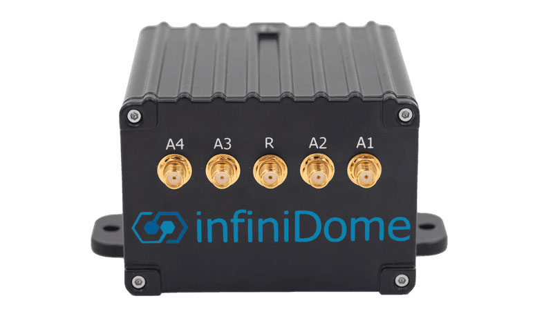
Anti-Jamming Device
Provides protection from three directions of attack
The GPSdome 2 is tailored to defend small- to medium-sized tactical UAVs as well as manned and unmanned ground vehicles. With a small form factor (500 g, 87 mm x 91 mm x 61.55 mm) and minimal power consumption, GPSdome 2 is suitable for loitering munitions as well as UAVs. Fully retrofit and completely standalone, the system is compatible with almost any off-the-shelf GNSS receiver as well as standard active GNSS antennas, meaning that it can be integrated into existing GPS systems or into new product lines, manned or unmanned. With sophisticated algorithms and a proprietary RFIC, GPSdome 2 analyzes RF interference in the environment and combines multiple antenna patterns to create and dynamically steer three nulls in the direction of any hostile signal. GPSdome 2 provides simultaneous dual-frequency protection (GPS L1 + L2 or GPS L1 + GLONASS G1), creating up to three nulls, protecting from three jamming directions within each band in real time, making it suitable for PNT applications. The GPSdome 2 is a dual-use, non-ITAR device and comes with optional mil-spec compliance.
InfiniDome, infinidome.com
Command and Control
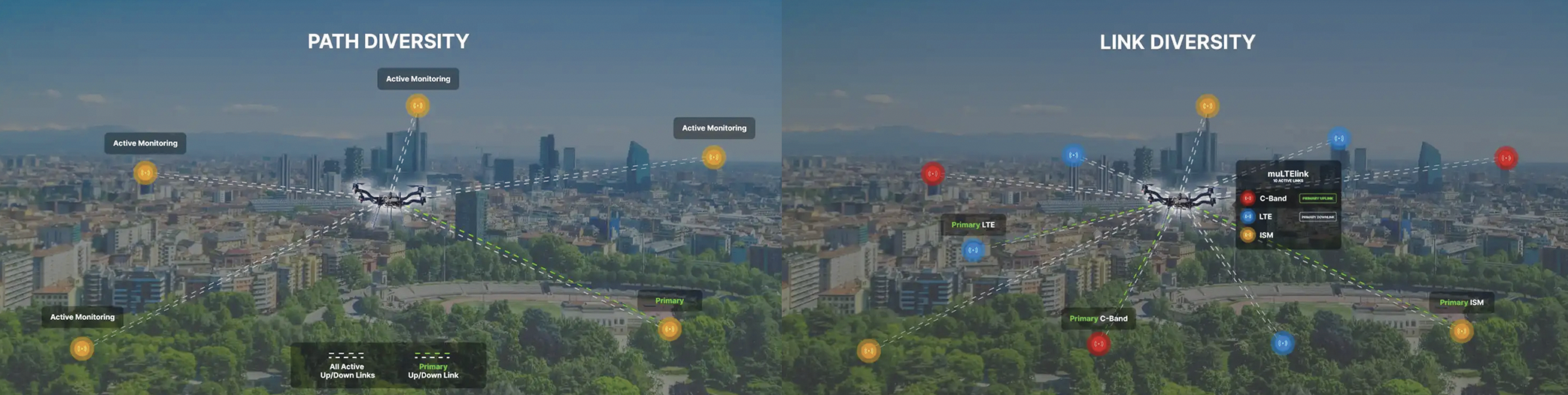
Designed for easy integration
The SkyLine C2 management platform and muLTElink airborne radio systems (ARS) are designed to integrate, which enables a self-healing command-and-control network capable of both path and link diversity. This eliminates lost-link possibilities over broad terrain and altitude ranges. MuLTElink ARS consists of two models — muLTElink915 and muLTElink5060, the core of the uAvionix C2 system. The muLTElink915 model combines globally licensed aviation LTE, enhanced with frequency hopping 902 MHz – 928 MHz industrial, scientific and medical frequencies capability. The muLTElink5060 model combines global LTE with aviation-protected 5,030 MHz – 5,091 MHz C-band. Each muLTElink model allows up to one external CNPC radio to be optionally connected to allow simultaneous use of all three frequency ranges, higher power C-band operation or future radio integrations.
uAvionix, uAvionix.com
VTOL UAV
With Sony a7R mark III and IV camera
Atmos has integrated the Sony a7R mark III and IV cameras into its vertical take-off and landing (VTOL) fixed-wing UAV, the Marlyn Cobalt. This will increase coverage and accuracy achieved in a single flight for surveyors. Both cameras have an ISO of 32,000, which is expandable to 102,400, and camera sensors with high megapixel count — 42,4 MP for the a7R III and 61 MP for the a7R IV. When combined with Zeiss’ 35 mm and 21 mm lenses, it enables UAV surveyors to achieve ground sample distance levels below one 1 cm. The integration of the two cameras enables Marlyn Cobalt users to map an area of 210 ha with centimeter-level accuracy in a single flight.
Atmos, atmosuav.com
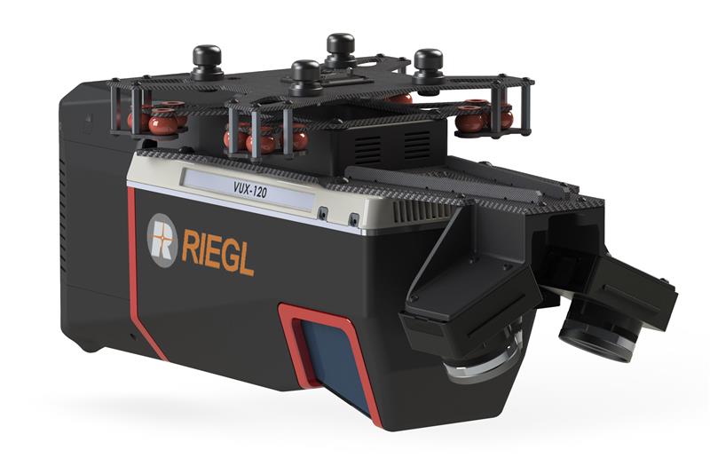
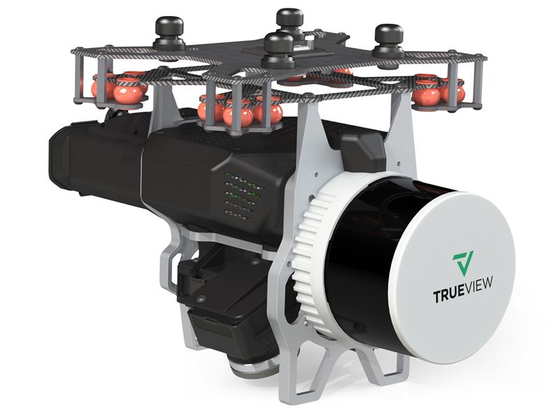
UAV and Lidar Systems
Suitable for geospatial professionals
TrueView 535 consists of updated lidar sensors, adding a third return, increasing mapping abilities below canopy. An additional third nadir camera offers another point of view and improves photogrammetry quality. It also includes a longer, usable lidar range to increase flexibility. TrueView 720 is a fourth-generation Riegl VUX-120 with three laser beam orientations. It provides high-point density corridor mapping. Using the Riegl VUX-120 with three laser beam orientations (nadir, +10 degrees forward and –10 degrees backward) and three oblique/nadir cameras enables data collection from more surfaces in one flight path. One application of TrueView 720 is scanning power lines. Users can capture the poles vertically, front and back. The extreme range of this system means it can be integrated with UAVs, airplanes or helicopters. In addition to the two sensor payloads, GeoCue has launched its LP360 software add-on for processing and visualization — the 3D Accuracy and the Accuracy Star hardware.
GeoCue, geocue.com
OEM
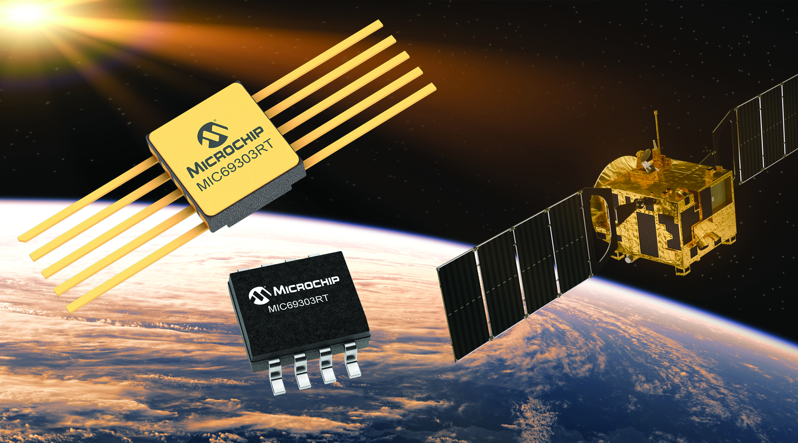
Voltage Regulator
Device for LEO space application
The MIC69303RT is a radiation-tolerant power management device for space application developers. It is a high-current, low-voltage device targeting low-Earth orbit space applications. The MIC69303RT operates from a single low-voltage supply of 1.65 v to 5.5 v and can supply output voltages as low as 0.5 v at high currents. It offers high-precision and low dropout voltages of 500 mv under extreme conditions. The MIC69303RT is a companion power source solution for microcontrollers, such as the SAM71Q21RT and PolarFire field-programmable gate arrays. MIC69303RT is designed for harsh aerospace applications and remains operational in temperature ranges from -55 C to +125 C.
Microchip Technology, microchip.com

LEO Satellite Device
Designed for GNSS/PNT lab testing
SimORBIT is a low-Earth-orbit (LEO) satellite solution software designed to aid developers in determining LEO orbits more accurately for GNSS/PNT lab testing. The software replicates LEO orbits so that simulations can provide the realistic environment of a LEO satellite, including gravitational and atmospheric impacts the satellite could encounter in space. Developers can create non-ICD signals via I/Q injection, or by the “Flex” feature, generating space-centered PNT signals to be developed in the lab as realistically as possible. Spirent Communications developed SimORBIT in partnership with SpacePNT.
Spirent Communications, spirent.com
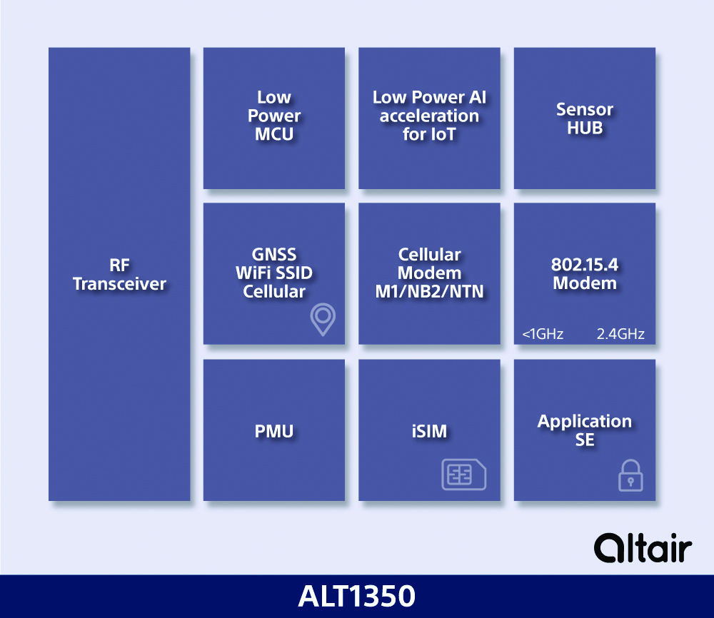
5G Chipset
Includes GNSS
The ALT1350 implements GNSS, cellular and Wi-Fi-based location in a single chipset. The cellular LTE-M/NB-IoT chipset is designed to enable additional low-power, wide-area (LPWA) communication protocols; intermittent LTE and GNSS (GPS/GLONASS) navigation for low-cost applications; and concurrent LTE and L1/L5 GNSS for tracking applications. The ALT1350 incorporates a sensor hub to collect data from the sensors while maintaining ultra-low power consumption. It also provides cellular and Wi-Fi-based positioning and is tightly integrated to provide power-optimized concurrent LTE and GNSS to accommodate various tracking applications, which can be demanding with a single chip. The chip is designed to enable deployments for the internet of things (IoT), including location technologies.
Sony, altair.sony-semicon.com
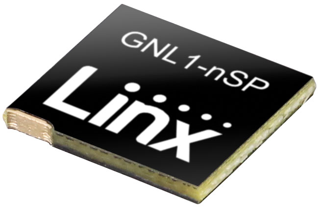
Embedded Antenna
Supports multiple satellite constellations
The ANT-GNL1-nSP is a surface-mount embedded GNSS antenna supporting GPS, Galileo, GLONASS, BeiDou and QZSS in the L1/E1/B1 bands. The ANT-GNL1-nSP antenna exhibits high performance in a compact size (10 mm x 8 mm x 1 mm) and features linear polarization and an omnidirectional radiation pattern. The antenna is available in tape and reel packaging and is designed for reflow-solder mounting directly to a printed circuit board for high-volume applications.
Linx Technologies, linxtechnologies.com
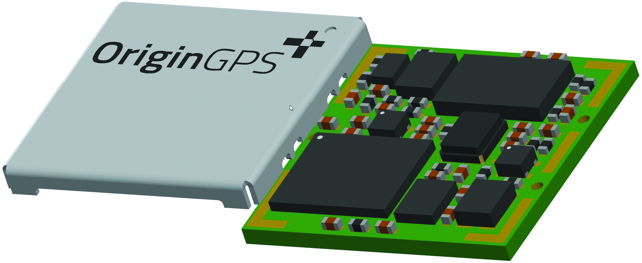
GNSS Module
Based on a MediaTek chipset
The ORG4600-MK01 dual-frequency module provides higher precision than the company’s previous modules. It has sub-1 m precision at a cost lower than that of the company’s first L1+L5 module, the ORG4600-B01, which is based on Broadcom’s chipset. The 10 mm x 10 mm ORG4600-MK01 was designed for applications deployed in challenging environmental conditions. The solution also includes RTCM, a logger and accurate orbit prediction.
OriginGPS, origingps.com
MAPPING
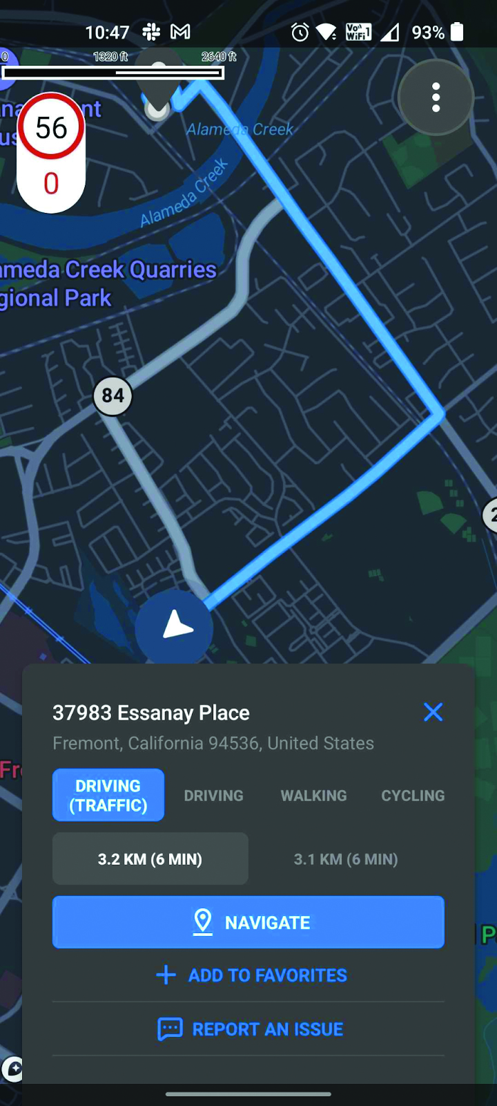
Navigation Software
Includes enhancements to existing software and more
Navigation software development kit version 2.9 provides pre-built applications compatible with Android and IOS. SDK v2.9 provides the primary navigation components across a workflow using lines of code instead of starting from square one. The drop-in user interface is customizable to reflect a developer’s brand, obviating the need to manually develop a full end-to-end application. Navigation SDK Copilot — a backend analytics tool for CX on navigation applications — collects trace files of navigation sessions and search analytics data from users. Developers can use this data to gather feedback and collective user data to create touch points with users and improve application experience based on their data-drawn conclusions. Matrix API has been updated to support scheduled departure times and provide optimal driving routes, creating a more accurate estimated time of arrival.
Mapbox, mapbox.com

Defense Platform
For developing Android applications
LuciadCPillar is designed for the development of mobile applications for dismounted soldiers in the field. Developers can build applications with 2D and 3D views. It features military symbology and supports many geospatial data types including vector data, raster data, elevation data, point clouds and 3D meshes. It has the same capabilities found in desktops, in-vehicle and browser applications built with LuciadLightspeed, LuciadCPillar and LuciadRIA. The platform offers capabilities to match high-resolution screens, graphic processing units and multi-core processors including the ability to display 3D data in mobile applications. LuciadCPillar supports ARM processors and an application programming interface, which aligns with the Android developer experience. Impact, a French system integrator, partnered with Hexagon to test LuciadCPillar and will integrate it into its Delta Suite product, which is used by the French Special Operations Command. LuciadCPillar is part of Luciad 2022.1, which is available now globally.
Hexagon, hexagon.com
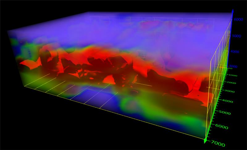
Surface Mapping
Designed for 3D surface mapping
The Surfer package is designed for 3D surface mapping and provides robust subsurface visualization and modeling functionality by incorporating many true 3D gridding and visualization tools. With the enhanced functionality, users can now model an additional variable, a C variable, such as a contaminant or chemical concentration, along with the traditional X, Y, Z values. Surfer also includes the ability to create a 2D map of a slice-through 3D grid, which users can move up and down through the grid, illustrating how the C value changes with depth. Part of Surfer’s enhancements is isosurface creation, enabling visualization of the 3D grid in the 3D view as an isosurface, providing another way to see how C data varies with depth or elevation. The new 3D-rendered volume functionality also allows users to visualize the 3D grid in the 3D view as a solid body by assigning colors to different C values, highlighting variations in the data.
Golden Software, goldensoftware.com