Colorado Springs, Colorado, and its vicinity are home to several key U.S. military organizations.
To the northwest is the U.S. Air Force Academy, which educates cadets for service in the officer corps of the United States Air Force and United States Space Force.
To the southwest, deep inside Cheyenne Mountain, is the North American Aerospace Defense Command (NORAD), a United States and Canadian organization charged with detecting, validating and warning of attacks against North America, whether by aircraft, missiles, or space vehicles. In a crisis, the four-star general in command of NORAD would pick up a direct line to the White House and tell the president whether nuclear armed missiles were on their way to the United States. He also commands the United States Northern Command, which is charged with defending the continental United States and Alaska.
I visited these two facilities 35 years ago, when I was a graduate student in international security at MIT. (The Air National Guard flew our group of MIT and Harvard students from Hanscom Air Force Base, near Boston, to Colorado Springs, with a stop at Offutt Air Force Base, home of the U.S. Strategic Command. One of the first Northrop B-2 Spirit, aka the Stealth Bomber, was there, under a tarp. A Harvard student decided to use the stop to go for a run. The MPs promptly arrested him and his professor had to bail him out, much to the amusement of us MIT students.)
In the southeast corner of the city is Peterson Space Force Base. To the east is the one that is of greatest interest to readers of this magazine: Schriever Space Force Base, the home of the GPS Master Control Station.
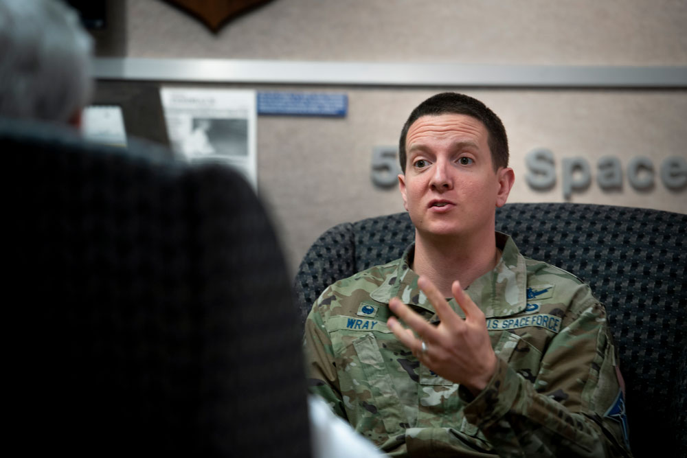
I recently visited the MCS at the invitation of Lt. Col. Robert O. Wray, Commander, 2nd Space Operations Squadron, which operates it. You can read excerpts of my interview with him here.
Wray gave me a tour of the MCS operations floor. During the tour, I was able to look at the dozens of computer monitors used by the GPS operators and to ask them many questions about their jobs. At any moment, 10 of them are on duty — eight uniformed military personnel and two civilian contractors. Later, I followed up with two members of the GPS Warfighter Collaboration Cell, which supports warfighters, combatant commands and, through the U.S. Coast Guard Navigation Center, more than four billion global civilian users.
Near the end of the tour, Wray surprised me with a question: “Would you like to send a command to a GPS satellite?” You can imagine my prompt answer. A moment later, I was seated at one of the consoles and entering an alpha-numeric string that I was copying from one of the screens. I was so delighted by the opportunity and so focused on entering the sequence correctly that I forgot to ask what command I was sending! Whatever it was, I assume it will help you get to your destination.
“Seen & Heard” is a monthly feature of GPS World magazine, traveling the world to capture interesting and unusual news stories involving the GNSS/PNT industry.
Image: Dennis Laughlin/iStock/Getty Images Plus/Getty Images
GNSS records Alaska earthquake data
Researchers in Alaska were able to compare the quality of GNSS and seismic station data when assessing the magnitude 8.2 Chignik earthquake near Dillingham, Alaska. Research recorded by Revathy Parameswaran and colleagues at the University of Alaska, Fairbanks, shows that GNSS and acceleration seismic data can be used interchangeably or in tandem to estimate rapid magnitude or ground motion. The research showed the Chignik earthquake velocity records were almost identical at co-located GNSS and seismic stations for observations at frequencies of less than 0.25 Hz.
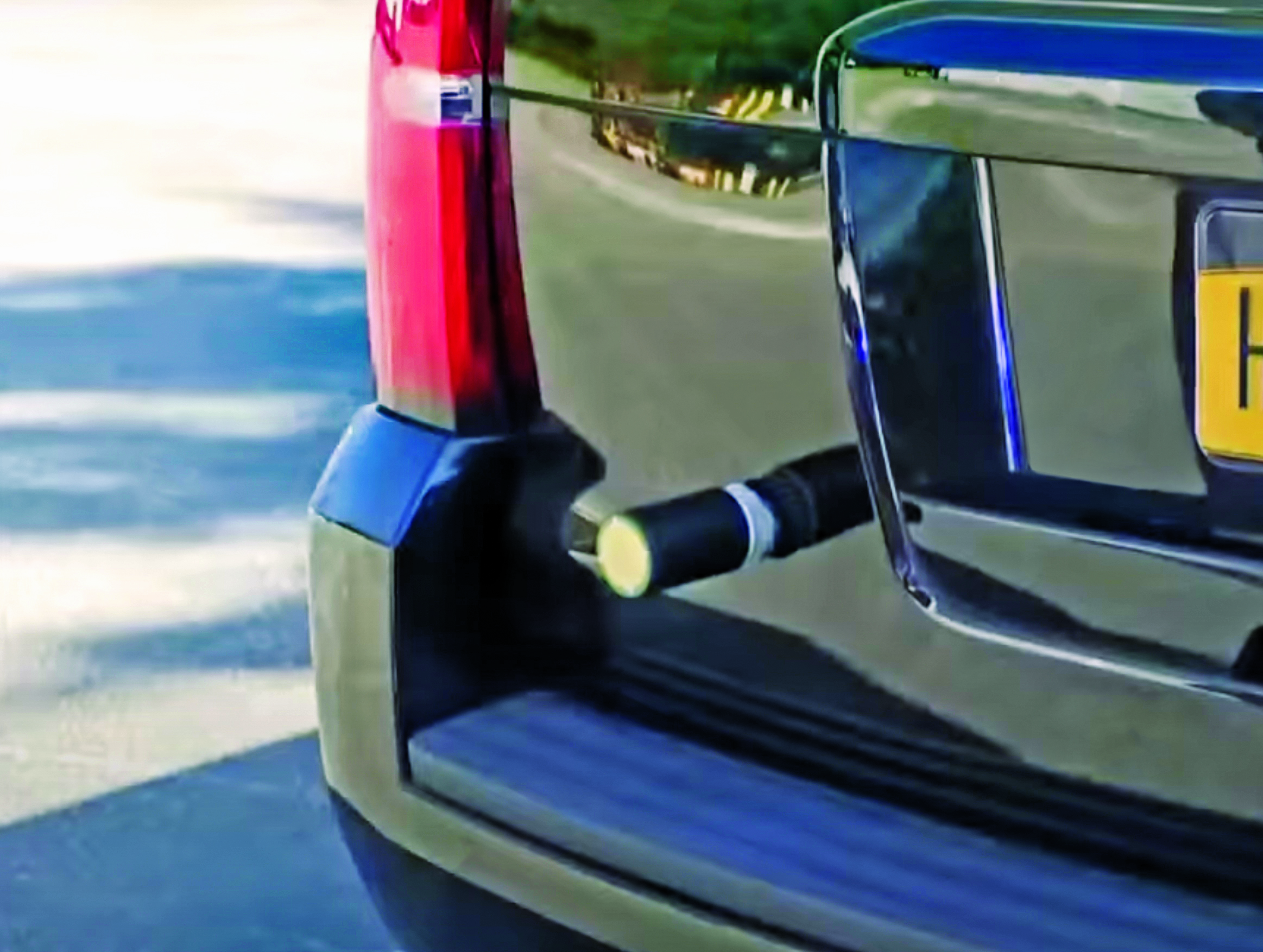
No more high-speed chases
Image: Screenshot from CBS New York video
The Old Westbury Police Department of Long Island, New York, has chosen a high-speed pursuit alternative — GPS-equipped darts that relay the current location of suspects, reported CBS New York. It took $36,000 to equip six patrol cars with the air-powered dart launcher, called StarChase, which can be activated from inside the patrol car. When the launcher is activated, it shoots onto the suspect’s vehicle a dart with a GPS receiver inside and an adhesive exterior. It is considered a safe alternative to high-speed chases and safe to use around pedestrians.
Shou Zi Chew, CEO of the popular app TikTok, testified before Congress that TikTok does not collect precise location data from its users. During the hearing, which lasted for more than five hours, Chew assured committee members the app does not collect nor distribute location data. TikTok is under fire as a bipartisan Senate proposal is aimed at banning the social media app, arguing it poses cybersecurity risks. The House Committee interrogated Chew regarding the app’s algorithmic feed, policies for young users and — given TikTok’s Chinese ownership — the amount of access the Chinese government has to user data.
Just some water, please
Image: Bob Douglas/iStock/Getty Images Plus/Getty Images
Satellite mapping data analyzed at Graz University of Technology’s Institute of Geodesy has revealed long-term drought conditions in Europe, reported GIM International. The data confirmed groundwater levels have been low consistently since 2018. The drought situation was originally published by Eva Boergens in “Geophysical Research Letters” in 2020 when she noted there was a severe water shortage in Central Europe during the summers of 2018 and 2019. There has been no significant rise in groundwater levels since then, and groundwater levels have stayed constantly low.
A roundup of recent products in the GNSS and inertial positioning industry from the May 2023 issue of GPS World magazine.
SURVEYING
Image: Septentrio
Corrections Program Provides documentation for GNSS receivers
The Agnostic Correction Partner Program facilitates the use of Septentrio GNSS receivers with high-accuracy services that provide varying levels of accuracy, coverage and delivery methods. This enables users to select the service that suits specific applications and business models. The program — which includes Polaris from Point One, Skylark from Swift Navigation, and PointPerfect from u-blox — provides documentation for the use of Septentrio receivers with these high-accuracy services. Agnostic corrections are useful in situations where multiple types of GNSS receivers are being used, such as in a large-scale surveying project. Septentrio, septentrio.com
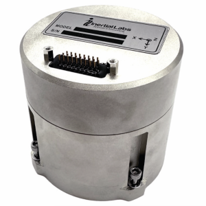
Image: Inertial Labs
Multi-Application IMU A compact, self-contained strapdown, advanced tactical-grade IMU device
The IMU-FI-200C measures linear accelerations and angular rates with its three-axis, tactical-grade, closed loop, fiber-optic gyroscopes and three-axis, high-precision MEMS accelerometers in motionless and high dynamic applications. The IMU-FI-200C is fully calibrated, temperature compensated and aligned to an orthogonal coordinate system. It contains more than 0.5°/hr gyroscopes and less than 2 mg bias repeatability over operational range accelerometers with low noise and high reliability. Continuous built-in test, configurable communications protocols, electromagnetic interference protection, and flexible input power requirements make the IMU-FI-200C suitable for a wide range of integrated system applications. Inertial Labs, inertiallabs.com
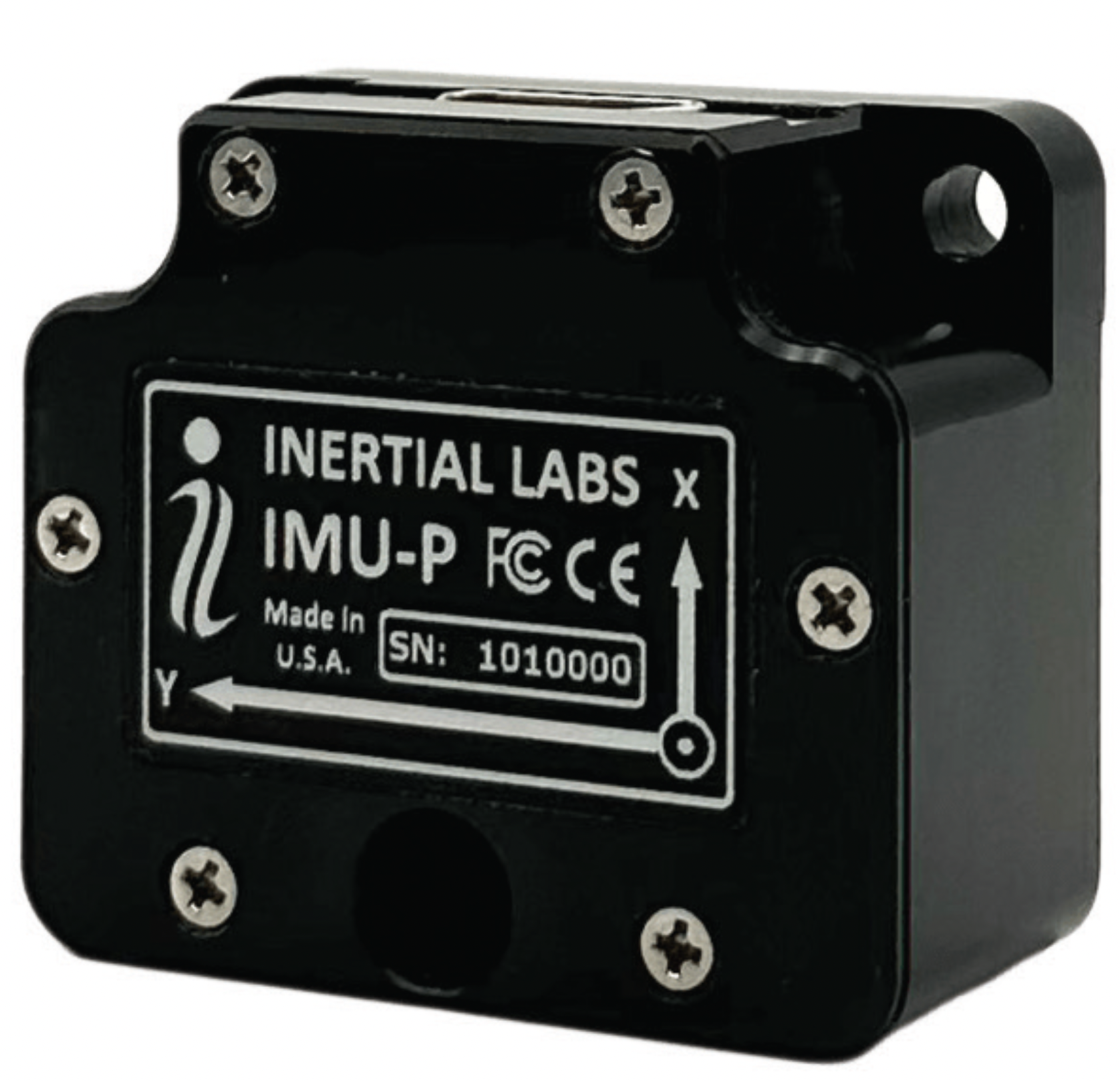
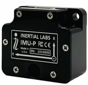
Image: Inertial Labs
MEMS IMU Suitable for applications such as antenna and line of sight stabilization systems, GPS-aided INS and more
The inertial measurement unit-P (IMU-P) is an advanced MEMS sensors-based, compact, self-contained strapdown, industrial- and tactical-grade inertial measurement system and digital tilt sensor that measures linear accelerations, angular rates and pitch-and-roll with three-axis, high-grade MEMS accelerometers and three-axis, tactical-grade MEMS gyroscopes. Angular rates and accelerations are determined with high accuracy for both motionless and dynamic applications. The IMU-P is fully calibrated, temperature compensated, and mathematically aligned to an orthogonal coordinate system. IMU-P demonstrates less than 1 deg/hr gyroscopes and 0.005 mg accelerometers bias inrun stability with low noise and high reliability. The IMU-P models collect data from an external source of GNSS to output full spectrum inertial navigation system data consisting of positions, attitude, velocity and time.
Inertial Labs, inertiallabs.com
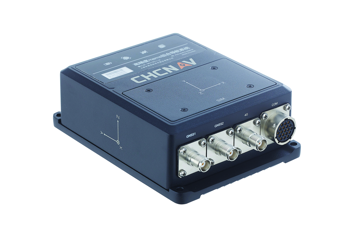
The CGI-610 GNSS/INS sensor is an advanced dual-antenna receiver designed for reliable and accurate navigation and positioning in challenging terrestrial, marine or airborne applications. Designed to meet the needs of 3D positioning and autonomous vehicle guidance applications, it provides high performance in urban canyons and other harsh environments where GNSS signals are lost or degraded. Incorporating GNSS technology and an industrial-grade inertial measurement unit, the sensor delivers accurate hybrid position, attitude and velocity data up to 100 Hz, driven by CHC Navigation algorithms. Its rugged and lightweight package ensures uninterrupted performance and meets high protection standards. CHC Navigation, chcnav.com
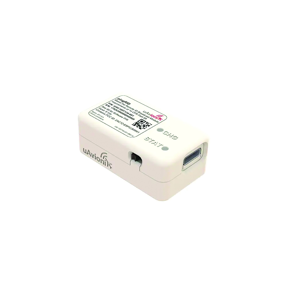
Image: uAvionix
Remote ID Module
Meets FAA standards
The pingRID meets the Part 89 remote ID standards of the Federal Aviation Administration (FAA), which will become effective on Sept. 16, to keep operators safe and compliant throughout a flight. The pingRID comes pre-configured and ready for use out of the box. After assigning the pingRID unique identification number to the aircraft’s registration with the FAA, operators can attach the battery-powered device to their UAV and prepare for flight. A set of LED indicators provides status on the battery charge, device readiness for flight and inflight operations. The compact, lightweight design fits most aircraft without significantly impacting performance. The module also can be quickly recharged via USB-C. The FAA’s final rule on remote ID requires all UAV pilots to meet the operating requirements of Part 89. For most operators, this will require flying a UAV equipped with standard remote ID, a remote ID broadcast module such as the pingRID, or flying at a Federally Recognized Identification Area. uAvionix, uavionix.com
MOBILE
Image: Orolia
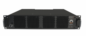
GNSS Simulator A positioning, navigation and timing test solution
GSG-7 delivers GNSS signal testing for location-aware applications and systems that require navigation or timing. The GSG-7 GNSS simulator features high-end performance with a 1,000 Hz simulation iteration rate, high dynamics, real-time synchronization, and simulation of all-in-view satellite signals. The GNSS simulator is suitable for development and integration projects that require high performance and an increased number of constellation licenses and satellites in view for a single antenna or trajectory. GSG-7 supports multi-constellation and multi-frequency GNSS simulations. It can be programmed to simulate operations with all current and future GNSS signals. Orolia, safran-navigation-timing.com
Image: Eos Positioning
GNSS Receiver Supports Galileo HAS
The Arrow Gold+ enables users to achieve better than 20 cm accuracy with 95% confidence using Galileo HAS. The Arrow Gold+ is one of the first high-accuracy GNSS receivers that supports Galileo HAS and is designed for the GIS market. Additional signal support for Arrow Gold+ includes: the concurrent use of the BeiDou B3 and GPS L5 signals as well as GLONASS, BeiDou, QZSS and IRNSS signals. Eos Positioning Systems, eos-gnss.com
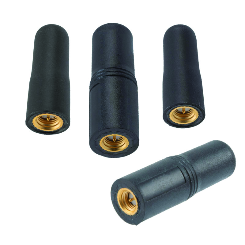
Image: Pasternack
Mil-Spec GPS/GNSS Antennas Meets military specifications for use in several small form factor and mobile applications
The PEANGPS1006, PEANGPS1007, PEANGPS1008 and PEANGPS1009 mil-spec GNSS antennas are engineerered
for environmental performance according to the MIL-STD-810G standard and include multi-standard GPS L1, Galileo E1 and GLONASS options. They are IP67 rated and available in passive and active versions and provide coverage from 1,597 MHz to 1,607 MHz. The GNSS antennas feature linear polarization for cross-polarized isolation, nominal gain options of -3 dBic and 10 dBic, and SMA mounts. The mil-spec GNSS antennas are available now.
Pasternack, Pasternack.com
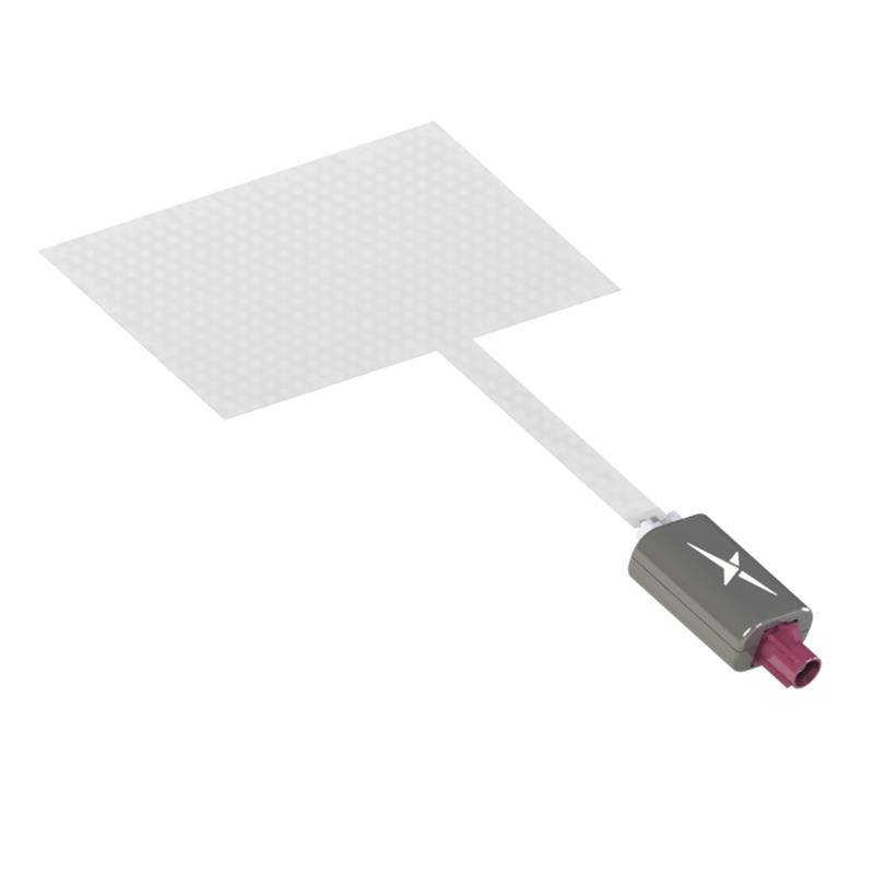
TFX62.A. (Image: Taoglas)
Near-Invisible Antennas Supports cellular Wi-Fi and GNSS technologies
The TFX62.A, TFX257.A and TFX125.A offer an alternative to standard opaque antennas, with “peel and stick” mounting capabilities to any nonmetal surface. The TFX62.A, TFX257.A and TFX125.A come with an adhesive and have an enclosed carrier terminated with a FAKRA connector for easy installation. The TFX series antennas leverage a sub-millimeter thick hybrid transparent conductive film that offers designers an invisible antenna solution. They are suitable for mobility, public infrastructure, medical devices, transportation and emerging IoT applications. Use cases for the antennas include electric vehicle chargers and parking meters, smart buildings and transportation vehicles.
Taoglas, taoglas.com
Image: CHC Navigation
3D Grade Control System For motor graders
The TG63 comes with a tightly coupled dual-GNSS positioning system and inertial sensor, and provides reliable 3D positioning and heading to ensure accuracy of the grader blade within ±2 cm. The TG63 is designed to withstand the harsh environment of construction sites and supports multiple applications, including real-time kinematic networked transport of RTCM via internet protocol and ultra-high frequency base stations.
CHC Navigation, chcnav.com
OEM
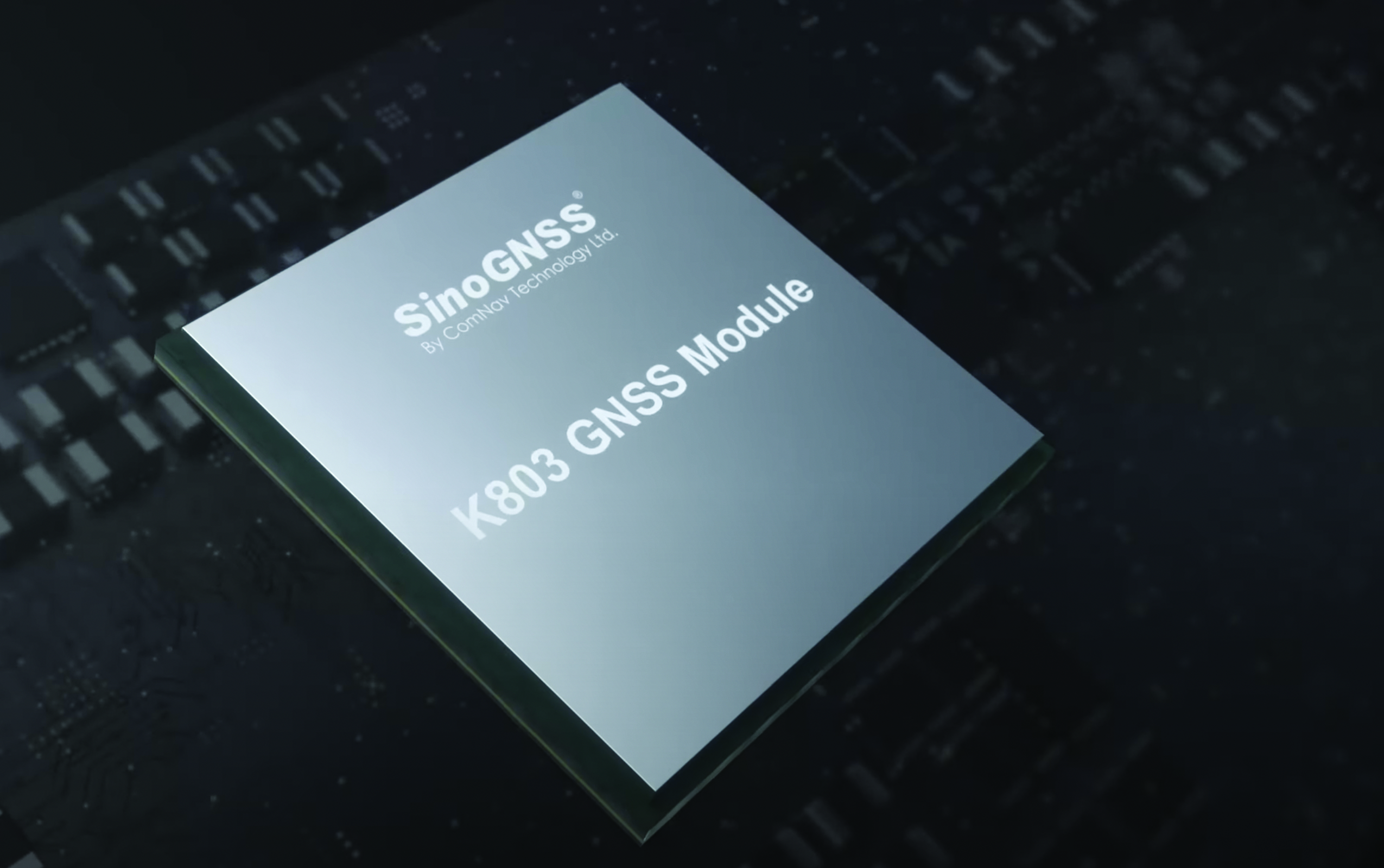
Image: ComNav Technology
GNSS Modules Now compatible with Galileo HAS
K8 series GNSS modules can use the Galileo High Accuracy Service (HAS) precise-point positioning (PPP). The PVT algorithm upgrade to the K8 series module supports Galileo HAS with an accuracy of 20 cm horizontally and 40 cm vertically. Galileo HAS provides free access to information necessary to estimate accurate positioning using a PPP algorithm in real-time through the Galileo signal E6-B and an internet connection. The improved performance capabilities provide a higher level of accuracy for industries such as UAV, autonomous driving, intelligent transportation, agriculture and more. ComNav Technology, comnavtech.com
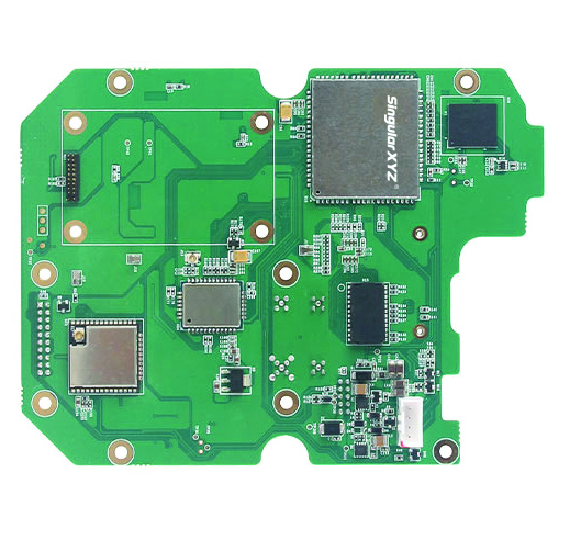
Images: SingularXYZ
Development Kit Designed for GNSS-related development integration
The DK100 development kit is a multi-functional kit with selectable single-antenna and dual-antenna modules, full constellation tracking and centimeter-level positioning. It is a ready-to-use kit designed to simplify integration efforts and increase compatibility with a variety of applications. The DK100 reserves standard adapter board interfaces to connect different GNSS modules and radio modules to meet specific needs. The development kits are coupled with a 4G module, Wi-Fi, Bluetooth, Ethernet modules, large memory and status indicators on a single PCBA. The DK100 comes with a web page for easy configuration. With Ethernet and Wi-Fi access, users can monitor device status and configure working mode and data transmission settings on the web page. The centimeter-level DK100 can be integrated in a range of horizontal and vertical applications, such as CORS construction, precision agriculture, construction machinery, smart navigation, monitoring, robotics, unmanned systems and more. Singular XYZ, singularxyz.com
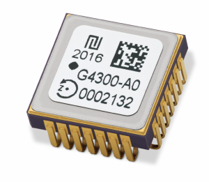
Image: TDK Corporation
Digital MEMS Gyroscope A high stability and vibration-tolerant gyroscope for dynamic applications
The GYPRO4300 features a ±300°/s input measurement range, 200 Hz bandwidth, and 1 ms latency with a closed-loop architecture that enables high linearity and stability. The GYPRO4300 has bias instability of 0.5°/h as a typical value and a maximum value of 2°/h. The GYPRO4300 is suitable for applications such as railways, land vehicles, vertical take-off and landing aircraft and UAVs, marine and subsea systems, borehole drilling and surveying instruments. The GYPRO4300 is available now for sampling and customer evaluations. Evaluations of the sensors also can be made with an Arduino-based evaluation kit that provides built-in testing functionalities such as output reading and recording, recalibration and digital self-tests. TDK Corporation, tdk.com
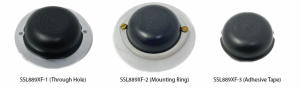
Image: Tallysman Wireless
GNSS Antenna Small, light, and dual-band
The SSL889XF employs Tallysman’s Accutenna technology providing GPS, QZSS L1/L2, GLONASS G1/G2/G3, Galileo E1/E5b, and BeiDou B1/B2b coverage. The SSL889XF antenna is designed for precision dual-frequency positioning where a light weight and a low profile are important. The SSL889XF antenna element is 48 mm in diameter and 20 mm tall and weighs ~50 g. It has a tight average phase center variation of less than 10 mm for all frequencies and overall azimuths and elevation angles. The SSL889XF is available in three versions. Model SSL889XF-1 has an integrated 61 mm ground plane and two mounting holes. Model SSL889XF-2 has a mounting collar, and model SSL889XF-3 is the antenna only and is attached using adhesive tape. All models have a female MCX connector. The SSL889XF antenna also supports Tallysman’s eXtended Filtering (XF) technology. Tallysman Wireless, tallysman.com
Image: ComNav Technology
Datalink Module Suitable for GNSS-based systems
The U702 datalink module is a RX/TX data link module that supports the LoRa modulation technique. Its compact, surface-mounted design and robust electromagnetic compatibility enable easy integration into GNSS systems such as robotic lawn mowers. With the LoRa modulation technique, the U702 has low power consumption, reception power of 0.025 w, and a working distance up to 1.5 km. It also enhances the ability to protect GNSS systems against various interference — making it possible to have high reception sensitivity, a low error rate, and high reliable data transmission even in harsh environments.
ComNav Technology, comnavtech.com
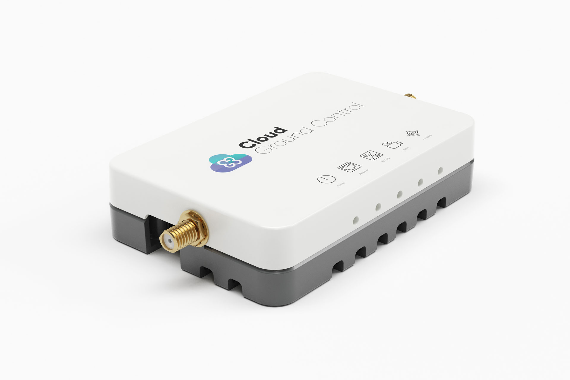
Image: Cloud Ground Control/Advanced Navigation
Fleet management device For air, land and sea vehicles
CGConnect can securely connect UAVs and vehicles into one autonomous fleet across land, sea and air, regardless of manufacturer or model. This provides mission planners and operators with full situational awareness for search and rescue, emergency response and disaster relief. Artificial intelligence (AI) algorithms are running in the cloud, relaying real-time camera feed data to the end user to support missions such as object detection, tracking and thermal imaging. The flexible and customizable open platform is operating on industry standards, which multiplies potential product applications and enables diverse autonomous vehicles and payloads to operate as a coordinated fleet. High-grade security safeguards data and IP from vulnerabilities and security breaches, helping users meet compliance obligations. Additionally, CGConnect supports edge AI to perform intensive object identification and classification directly on the vehicle for dynamic missions. CGConnect is available for pre-order. An OEM option is available. Cloud Ground Control/Advanced Navigation, cloudgroundcontrol.com/advancednavigation.com
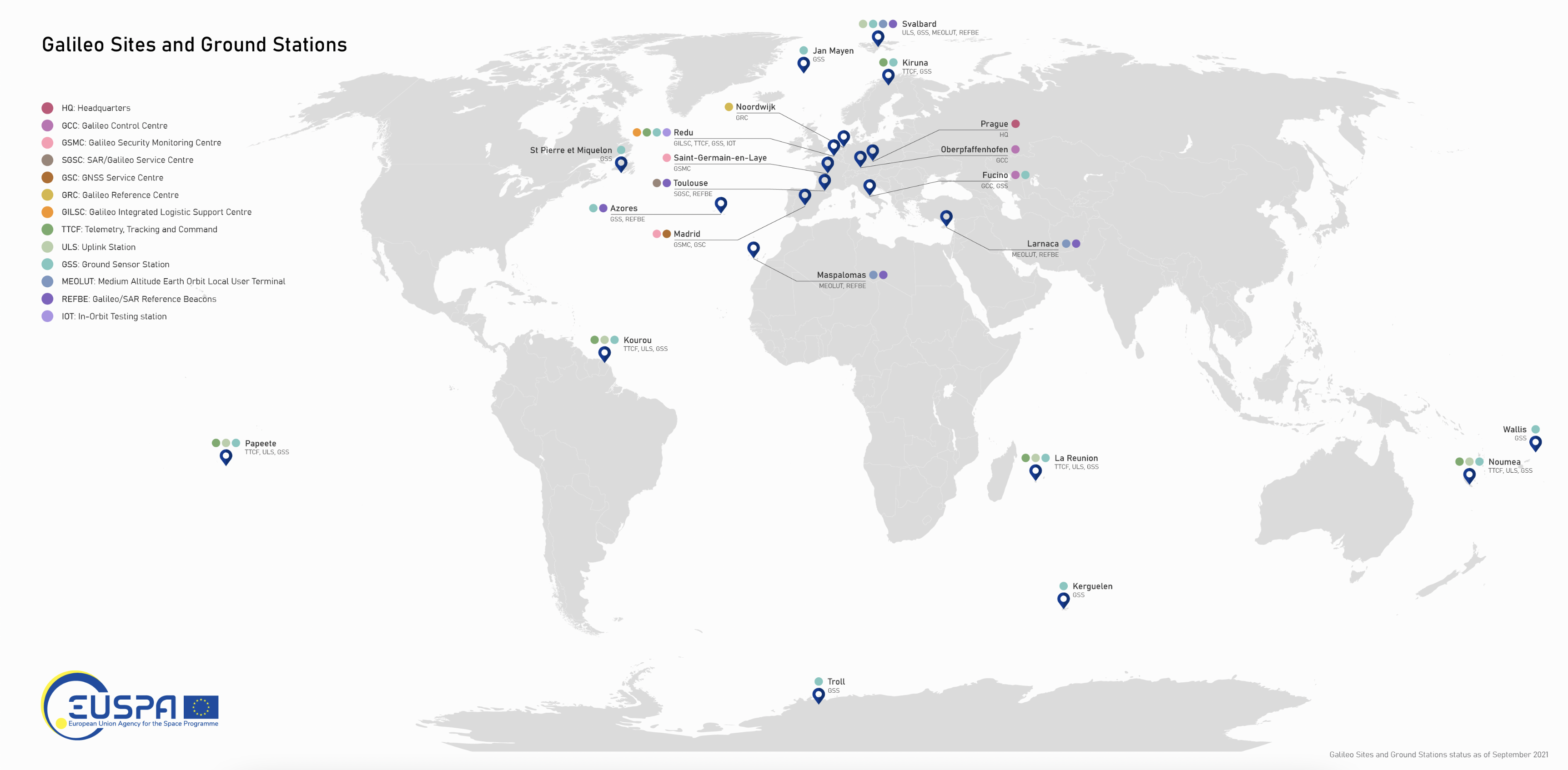
The newest addition to the network of Galileo sensor stations (GSS) is up and running in Wallis and Futuna, a French territory in the South Pacific consisting of three main islands and many tiny islets. It enables increased Galileo coverage in the southern hemisphere.
The European Union Agency for the Space Programme (EUSPA) reported that the decision for the new station was made in June 2020; however, due to COVID-19, its deployment did not begin until summer 2022. In October 2022, the second mission to Wallis and Futana took place to complete the deployment and connect the station to the ground mission segment network for data collection.
The GSS is a network of antennas deployed at remote locations around the world. They have small, omnidirectional receiving antennas 50 cm high that check the accuracy and signal quality of individual satellites and pinpoint current satellite orbits. Establishing GSS is difficult and requires security accreditation by EUSPA’s Security Accreditation Board.
To make the best use of the Galileo services, users rely on more than just the satellites. Dedicated facilities such as the Galileo control centers, sensors, and uplink stations are important components that make up the Galileo ground segment — which supports the service provision of Europe’s GNSS. The GSS is an important element of Galileo’s ground segment.
Airbus Helicopters and the French Armament General Directorate (DGA) tested the unmanned aerial system (UAS) VSR700 for the first time in an operational configuration from a ship at sea.
The VSR700 performed 80 fully autonomous take-offs and landings from a civil vessel off the coast of Brittany in the west of France at the beginning of May.
In 2022, the autonomous take-off and landing capabilities of the VSR700 were tested from the same vessel using an optionally piloted vehicle based on a modified Guimbal Cabri G2 equipped with the autonomous take-off and landing (ATOL) system, developed for the VSR700. This time the test campaign took place with the SDAM demonstrator and fully validated the capabilities of the system as part of the Système de Drone Aérien pour la Marine study that was awarded to Airbus Helicopters and Naval Group in 2017.
Autonomous take-off and landing capabilities are a key asset of the VSR700 and are made possible with the use of the Airbus DeckFinder system. This enables autonomous launch and recovery of UAVs with an accuracy of 10cm-20cm during challenging operations in harsh environmental conditions, independently of GNSS/GPS and regardless of degraded visual conditions.
This test campaign follows two series of trials that were conducted with the DGA in late 2022 and early 2023, from the Levant Island test center located in the south of France. During these trials, the SDAM prototype demonstrated its ability to operate in a maritime environment.
The handling qualities of the aircraft were tested as well as the capabilities of the sensors (a maritime surveillance radar, an electro optical sensor, and an AIS receiver) alongside the mission system developed by Naval Group.
The next development steps will see the second VSR700 prototype perform its maiden flight ahead of flight testing onboard a French Navy FREMM during the second semester of this year.
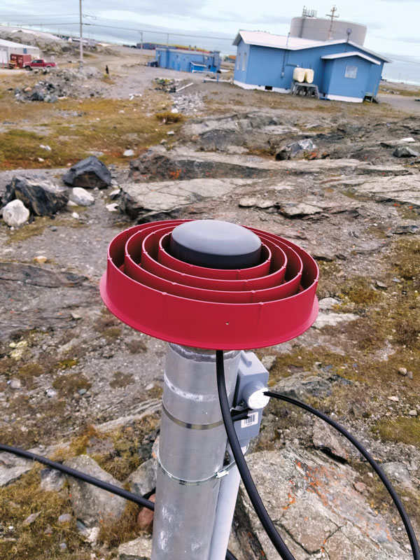
Sea level changes are monitored using a VeraChoke antenna at a GNSS observing station in Canada. (Image: Natural Resources Canada)
All antennas for global navigation satellite systems (GNSS) receivers serve the same fundamental function: to capture, filter, amplify the observed signals and relay them to the receiver. For high precision applications, certain design techniques allow for more accurate signal acquisition. These techniques involve the three main components of a GNSS antenna: the radiating element, additional ground plane, and the radio frequency (RF) frontend also called low noise amplifier (LNA).
Ceramic Patch Antennas
First, we will look at the antenna radiating element. Let us look at a common style of antenna that you might see in a surveying rover, a “patch” and associated ground plane. The patch, typically a metalized square or disk printed on a dielectric substrate, set in the middle of the ground plane, can have one or more feed points connecte to the RF frontend. For certain applications we may use only one feed point, which yields a narrow bandwidth; in other words, the circular polarization bandwidth of a single feed patch is very narrow. Single feed patches are then generally used for GPS L1-only applications. With two or more feed points, the circular polarization of the antenna is drastically improved over wider bandwidth. Putting it simply, for a two feed point antenna, the orthogonal currents flowing on the metalized surface of the patch are detected independently in both axes, one feed for each axis. The two signals are then combined using a 90 degrees hybrid coupler to reconstruct the GNSS information from the satellite. To cover multiple bands, such as L1 and L2, or L1 and L5, multiple patches can be stacked together.
Precision and Helicals
High performance dual feed patch antennas typically deliver phase information error of about 10 mm, though that does not mean you cannot achieve any higher. Depending on design specifics, other antenna technologies can achieve even higher precision. Helical antennas, another common design, yield a precision of at least 5 mm. They are taller than patch antennas, with a coil of four metallic elements pointing upwards. A key advantage is that helical antennas are less impacted by the absence of ground plane and still mitigate multipath interference in such a situation. Although being exceptionally light, a clear disadvantage of helical antennas is their height. However, a reduced height version of the technology is being developed that performs on par to the original technology.
Higher Accuracy
The key to even higher precision, down to an accuracy of less than 1 mm, is in the design of the individual components of the antenna element. Traditionally, the highest performing elements are quite sophisticated and difficult to manufacture, therefore they are quite expensive, and can be in limited supply. For certain legacy geodetic antennas, typically built into a choke ring, the element alone might cost several thousand dollars. We have taken inspiration from these designs and developed variations that have been able to deliver higher performance at a much lower cost.
Crossed Dipole Antennas
One of those approaches is an element that uses two wide band crossed dipoles mounted at 90 degrees from each other. The dipoles are connected directly to the RF frontend. Again, we combine two linearly polarized components through a 90 degrees phase coupler to reconstruct the right hand circular signal. Using RF engineering techniques these dipoles are coupled to other antenna element components, such as metalized “petals”, to improve or enhance performance in various ways. These enhancements include a wider bandwidth enabling the coverage of the entire GNSS spectrum, a more favorable radiation pattern; high low-elevation gain, and higher gain at zenith. This technology is the basis of our VeroStar, VeraPhase, and VeraChoke lines of antennas.
The rate of crustal motion is estimated using data collected by a VeraChoke antenna at a GNSS observing station at Rankin Inlet, Canada. (Image: Natural Resources Canada)
Ground plane and ChokeRings
Two additional elements that enhance certain antennas’ performance are ground planes and choke rings. An antenna does not necessarily need an external ground plane, a prime example being helical antennas. However, some antennas, such as patches, perform optimally with one. A choke ring is often used to attenuate signals from the horizon or below it, which are generally unwanted signals as they are typically due to multipath. To an extent, the concentric rings of a choke ring create a highly resistive surface for any low-elevation signals. Beyond the physical and electrical design aspects of the antenna, remaining interference from multipath may be mitigated algorithmically in the receiver.
RF Frontend
Coming after the radiating element is the RF frontend, another key component of high precision antennas. RF frontends include amplifier stages — which, as the name implies, amplify signals — and filters, such as ceramic or surface acoustic wave (SAW) filters, which reduce out-of-band signals while allowing in-band signals through. The GNSS signals from space are very weak and need to be amplified, often by a factor of 1,000 or more. There are two techniques for using filters: pre-filtering and in-line filtering. Pre-filters come before the first amplifier stage and prevent in band harmonics. In today’s congested RF spectrum, nearby signals or their harmonics can affect the RF frontend to the point that a non-prefiltered antenna will put the whole GNSS system at risk. A pre-filter mitigates this, but there is no free ride. Including a pre-filter in the RF frontend slightly increases the noise figure, which will slightly reduce the receiver signal-to-noise ratio (C/N0). However, a pre-filtered antenna will ensure the GNSS system to continue to operate in the presence of interference. Filters may also be applied between amplifier stages to further attenuate out-of-band interference.
In conclusion, a GNSS antenna is the optimal sum of three components: a well-designed radiating element, carefully selected external ground plane, and a high performing RF frontend. Technologies and models are available for every specific application that may arise. For example, patches are good general purpose antennas with a low-profile, helicals are lightweight and operate well without a ground plane, and crossed dipole antennas are ideal full GNSS rover and base station applications.
While I’m likely preaching to the choir here, GNSS cannot work unless we have an accurate description of the orbits of the satellites and the behavior of their atomic clocks. The accuracy with which this information is provided to a receiver or data processing software is the most important component of the error budget of GNSS positioning, navigation and timing and constitutes most of what is known as the signal-in-space (SIS) range error.
Each GNSS satellite broadcasts a description of its orbit or ephemeris along with the offset of its active clock from the system’s time standard in a navigation message decoded and used by the receiver. These data are predictions of the orbit and clock offset as computed by the system’s ground control segment and uploaded to each satellite. A recent assessment by U.S. Space Systems Command of the GPS SIS error averaged across all active satellites for a one-week period was about 50 centimeters, root-mean-square. While this is entirely adequate for many GNSS uses, it falls short of the required accuracy for high-demanding applications such as surveying, geodesy, atmospheric sensing, reference frame studies and tectonic monitoring. Which is why various organizations both private and public compute very accurate orbits and clocks and provide these to users. These computations, using data from global receiver networks, are very exacting and model the tiniest effects on the (primarily) carrier-phase measurements these receivers provide.
These effects include the offset in the electrical phase centers of a GNSS satellite’s transmitting antenna from the satellite’s center of mass and how that varies with the direction of the signal from the satellite to a receiver on Earth. Furthermore, this behavior must be calibrated and modeled for each radio frequency that the satellite transmits. Another effect that must be accounted for are the perturbations caused by non-perfect yaw-steering of a satellite’s solar panels. These panels continuously track the Sun but they have difficulty keeping up at orbit noon and midnight. Accurate models of the actual yaw angle are very important for high-precision GNSS orbits. As if these model requirements were not enough, the effect of solar radiation pressure on satellite orbits must also be modeled. While they don’t have (rest) mass, photons have energy and this can be imparted to satellites when they impinge on them. While a single photon has a negligible effect, the billions upon billions of photons making up sunlight do have a noticeable effect on a GNSS satellite’s motion and must be accounted for by orbit models.
One organization producing precise orbits for GNSS satellites – arguably the most precise in the world – is the International GNSS Service (IGS), a voluntary federation of more than 200 agencies, universities and research institutions across the globe. Several of these organizations each produce precise orbits, which they submit to the IGS to establish orbit products. One of these organizations is the Navigation Support Office (NSO) at the European Space Agency’s European Space Operations Centre. In this quarter’s Innovation column, a team of NSO engineers discusses how they have improved the orbit modeling of the GPS III satellites by around a factor of two with estimated orbit errors of about 2 centimeters or less. Wizardry? Not really – just rocket science.
To produce GNSS satellite orbit ephemerides and clock data with high precision and for all constellations, the Navigation Support Office of the European Space Agency’s European Space Operations Centre (ESA/ESOC) continually strives to keep up and improve its precise orbit determination (POD) strategies. As a result of these longstanding efforts, satellite dynamics modeling and GNSS measurement procedures have progressed significantly over the last few years, especially those developed for the European Galileo satellites. Because the accuracy of ESA/ESOC’s GNSS orbits has reached such a high level (about 1 to 3 centimeters), introducing a completely new type of GNSS satellite into the processing is not as easy as it used to be. New spacecraft models – the first and foremost being a model for a satellite’s response to solar radiation pressure (SRP) – are needed for the “newcomer” so that the quality of the overall multi-GNSS solution does not suffer. Just as important are spacecraft system parameters, or metadata, such as the location of the satellite antenna’s electrical phase center and the satellite attitude law.
In this article, we show the efforts we have made at ESA to bring the quality of our orbit estimates for the GPS Block III satellites up to par with those for Galileo and the earlier GPS satellite blocks. We report on the results from on-ground and in-flight determinations of the Block III transmit antenna phase center characteristics up to 17 degrees from the antenna boresight direction. Moreover, we take advantage of the non-zero horizontal offsets of the transmit antenna from the spacecraft’s yaw axis to estimate the satellite yaw angle during Earth eclipse season and present a simple analytical formula for its calculation. Finally, we describe the development and validation of improved radiation force models for the Block III satellites.
We start, however, by giving a brief overview of the GPS Block III program.
GPS BLOCK III
The U.S. Space Force GPS Block III (previously referred to as Block IIIA) is a series of 10 satellites being procured by the United States to bring new future capabilities to both military and civil positioning, navigation, and timing (PNT) users across the globe. Designed and manufactured by defense contractor Lockheed Martin (LM), the satellites are reported to deliver three times better accuracy, 500 times greater transmission power, and an eightfold enhancement in anti-jamming functionality over previous GPS satellite blocks. At ESA/ESOC, we are paying particular attention to this new tranche of satellites as they are the first to broadcast L1C, a new common signal interoperable with other GNSS, including Galileo.
At the time of this writing, there are six GPS III space vehicles (SVs) in orbit. The first one – nicknamed “Vespucci,” in honor of Italian explorer Amerigo Vespucci – lifted off atop a SpaceX Falcon 9 rocket from Cape Canaveral Air Force Station, Florida, in December 2018, and entered service on January 13, 2020. An additional four SVs are expected to be launched soon, before moving on to an updated version called GPS IIIF (“F” for Follow On). The first Block IIIF satellite is projected to be available for launch in 2026.
In view of the growing number of GPS III SVs in orbit, and soon to be joined by IIIFs, accurate spacecraft models and metadata information are becoming more and more important in order to maximize PNT accuracy.
SATELLITE ANTENNA PHASE CENTER PARAMETERS
GNSS signal measurements refer to the electrical phase center of the satellite transmitting antenna, which is neither a physical nor a stable point in space. The variation of the phase center location as a function of the direction of the emitted signal on a specific frequency is what we call the phase center variation (PCV). The mean phase center is usually defined as the point for which the phase of the signal shows the smallest (in a “least-squares” sense) PCV.
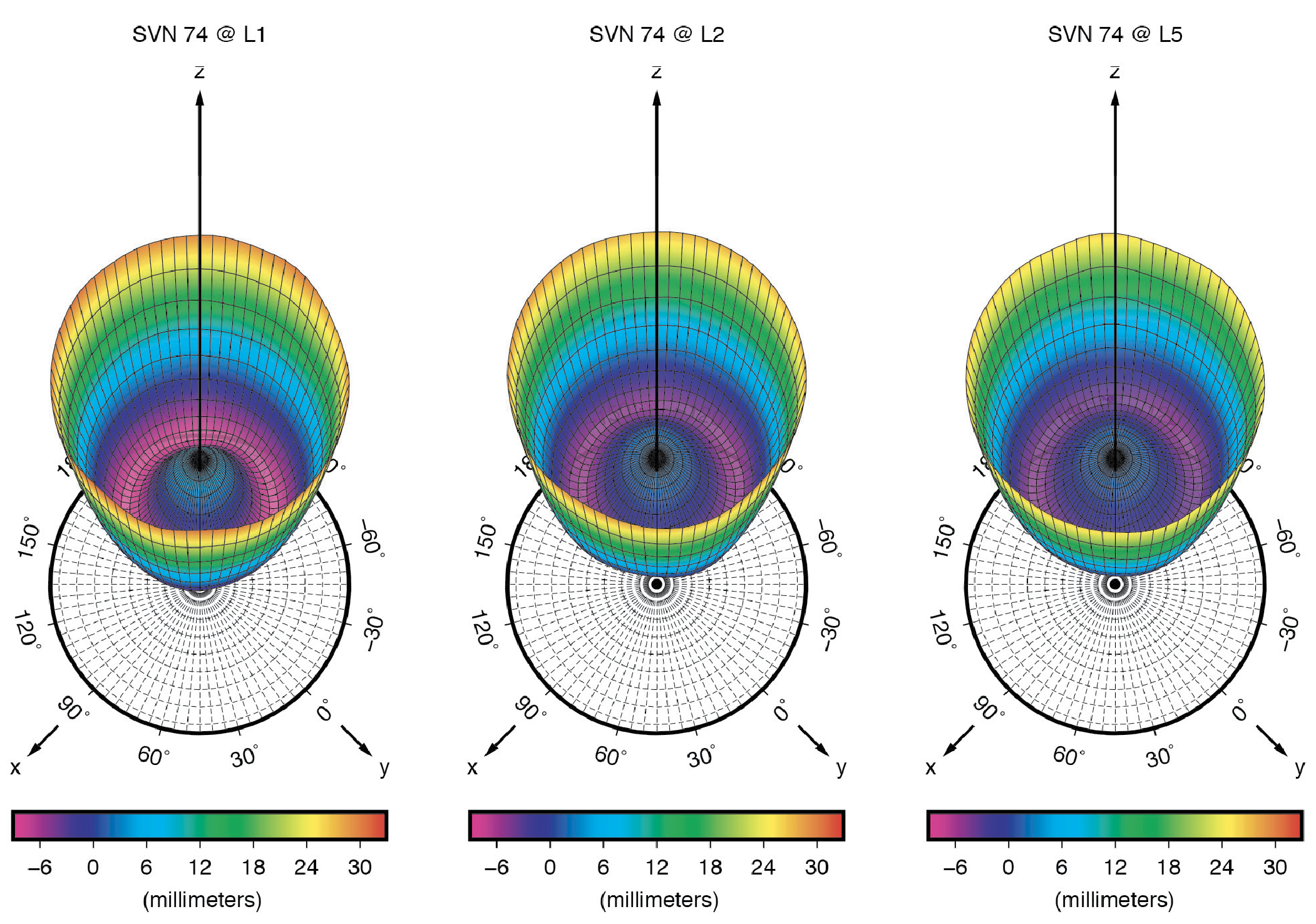
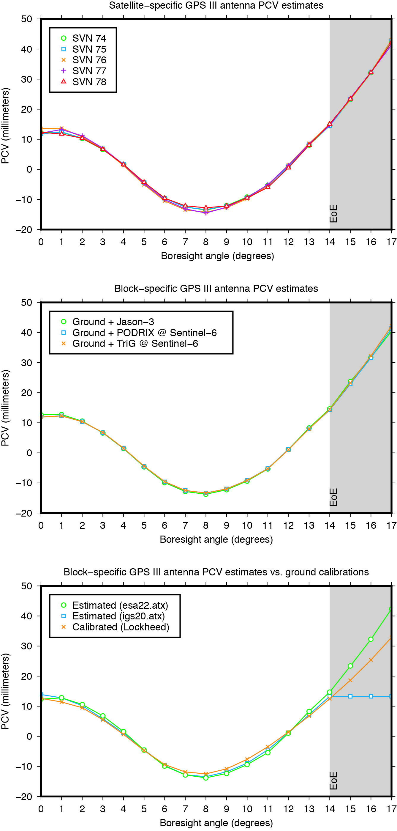
Figure 1: Ground-calibrated GPS Block III transmit antenna phase center variations (PCVs). (All figures provided by the authors).
The point of reference for describing the motion of a satellite, however, is typically the spacecraft center of mass (CoM). The difference between the position of the mean phase center and the CoM is what we typically refer to as the satellite’s antenna phase center offset (PCO). Both PCO and PCV parameters must be precisely known — from either a dedicated on-ground calibration or one performed in flight — so that we can tie our GNSS carrier-phase measurements consistently to the satellites’ CoM.
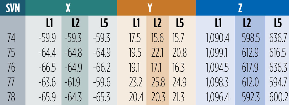
On-Ground Calibrations. Like for previous GPS vehicles, the Block IIR and Block IIR-M satellites, LM has fully calibrated the GPS III transmit antennas prior to launch at their ground test facilities. Antenna offset parameters for all three carrier signals (L1, L2 and L5) were posted on the U.S. Coast Guard Navigation Center (NAVCEN) website (www.navcen.uscg.gov) shortly after each satellite launch. In December 2021, NAVCEN released the PCOs for SV number (SVN) 78, along with updates to the first four satellites (see Table 1). About ten months later, in October 2022, the antenna pattern for each satellite and signal frequency were published (see Figure 1).
Table 1: Ground-calibrated GPS Block III transmit antenna PCOs in millimeters. (Image: GPS World staff)
The December 2021 offsets are referred to as predicted values at the end of year one on orbit. They differ from the previous ones by several centimeters in both vertical (Z) and horizontal (X and Y) directions. Particularly surprising are the X- and Y-PCOs, which were initially reported to be close to zero. The differences in the horizontal PCOs have generated uncertainty and debate, especially within the International GNSS Service (IGS) about which values to adopt for the new antenna model release (igs20.atx). Testing of the two different PCO datasets in our software demonstrated that the non-zero values as given in Table 1 are the significantly more accurate ones. We will return to this later in this article.
Combined Ground- and Space-Based Tracking. In this part of this article, we discuss the combination of dual-frequency tracking data from geodetic-quality GPS receivers in low Earth orbit (LEO) with those from a global receiver network on the ground to determine the phase center parameters of the GPS Block III transmit antennas. The LEO-based measurements were taken by the GNSS receivers on board the ocean altimetry satellites Sentinel-6 Michael Freilich and Jason-3. The 1,336-km altitude of both of these missions enables the estimation of the GPS satellite antenna PCVs from 0 up to 17 degrees from boresight while GPS receivers on Earth can only see the satellites up to a maximum angle of 14 degrees. The 14-degree limit is also referred to as the GPS satellites’ edge of Earth (EoE) angle.
For the modeling of the PCVs we follow the approach of the IGS using piece-wise linear functions of the boresight angle and constraining the PCV values to between 0 and 14 degrees to have zero mean. Furthermore, we employ fully normalized spherical harmonic expansions of degree 8 and order 5 to solve for the azimuth- and elevation-angle-dependent PCVs of the orbiting receiver antennas. The IGS standard antenna phase center corrections from igs20.atx are applied to all terrestrial receiver and GPS Block II transmit antennas.
Figure 2: GPS Block III transmit antenna PCVs as a function of boresight angle. The gray shaded area indicates the angular range that is inaccessible from the ground but relevant to high altitude LEO missions such as Sentinel-6 Michael Freilich or Jason-3.
The estimated Block III antenna PCVs are depicted in Figure 2. The estimates for the five individual antennas match each other to within 0.4 millimeters root-mean-square (RMS) (see Figure 2, top). The agreement among the PCVs that we get when processing the tracking data from each LEO receiver’s antenna separately is at the sub-millimeter level, too (see Figure 2, middle). Overall, the level of consistency suggests that the PCVs are of very good quality and that a block-specific representation is sufficient for precise applications. Comparison of the final block-specific PCV estimates against the values from the current IGS antenna model and from the ground calibrations shows strong agreement (RMS = 0.7 millimeters) between 0 and 14 degrees from boresight (see Figure 2, bottom). Beyond the 14-degree limit, the differences compared to the IGS standard are up to three centimeters, underlying the urgent need for an update of the igs20.atx file.
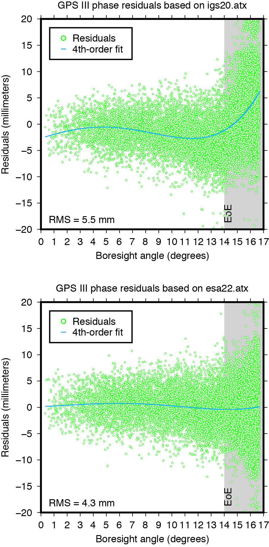
Applying the extended PCV corrections as part of the POD process to the GPS LEO receiver data shows significant improvement in the post-fit carrier-phase residuals when compared to the PCV corrections from the IGS legacy model. It removes a previously existing boresight angle-dependent trend and leads to a more than 20% reduction in the computed residual RMS (see Figure 3).
Figure 3: Post-fit residuals of GPS III carrier-phase data from Sentinel-6 Michael Freilich when using igs20.atx (top) and esa22.atx (bottom), respectively.
YAW MODELING
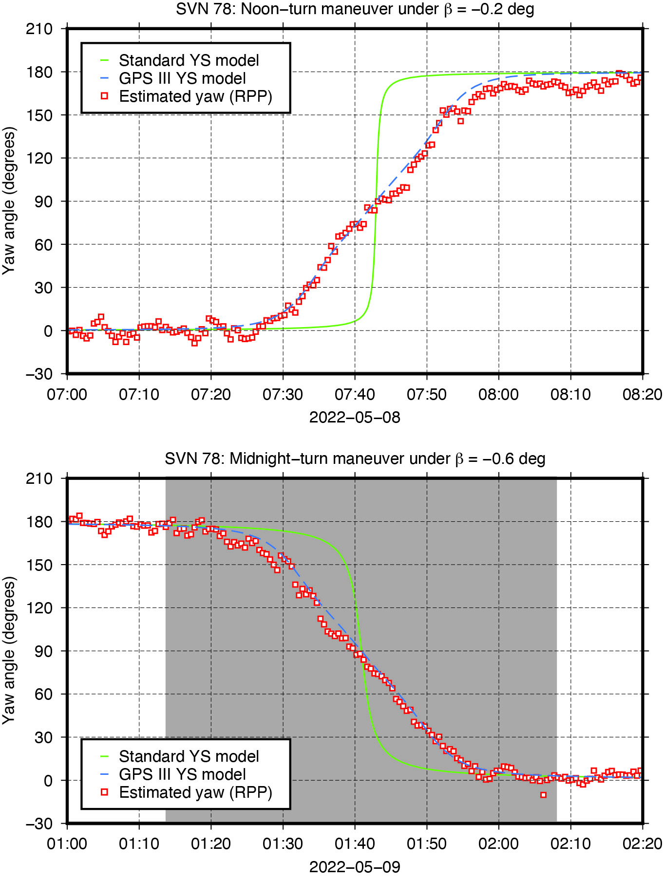
Figure 4: Yaw turn maneuver of GPS Block III satellite SVN 78 near orbit noon (top) and orbit midnight (bottom), respectively.
GNSS satellites cannot follow an ideal yaw-steering whenever the Sun elevation angle relative to the orbital plane (the so-called beta angle) gets too low and the yaw rate required to keep the satellite solar panels pointing towards the Sun exceeds the maximum satellite yaw rate. The strategies on how GNSS satellites perform rate-limited yaw-steering are different for each type of spacecraft and only partly documented for public users. Continuous knowledge of GNSS spacecraft yaw attitude, however, is important for kinematic and dynamic reasons. Errors in yaw are known to affect the modeling of transmit antenna phase center’s position, carrier-phase wind-up, and radiation pressure forces. On the other hand, when the mean antenna phase center location is offset from the spacecraft’s Z-axis, the satellite yaw state can be estimated instantaneously from the tracking data of a global receiver network. The approach behind this is commonly referred to as “upside down” or “reverse kinematic precise point positioning” (RPP). The horizontal antenna offset vector can be viewed here as a kind of rotating lever arm whose length determines the accuracy of the yaw angle estimates. Since the Block III X-offset is just 7 centimeters, one should not expect the same RPP accuracy as for other GNSS satellites like those of the GPS IIF or GLONASS-M series, which have an X-offset that is six (GPS IIF) or even eight (GLONASS-M) times larger.
Nonetheless, with more than three hundred ground stations, kinematic RPP works reasonably well even for GPS III as we can see from Figure 4, which shows the estimated yaw angle of SVN 78 while passing orbit noon and orbit midnight with a Sun elevation angle of almost zero degrees. The plots suggests that Block III satellites — unlike previous Block IIA and IIF SVs — perform their yaw slews near noon and near midnight in the same way and at the same yaw rate. In this respect, the yaw turn behavior is similar to that of the IIR/IIR-M satellites. However, with a maximum yaw rate of 0.10 degrees per second, the Block III satellites rotate only half as fast as those of the IIR/IIR-M family. What is also different is the start time of the yaw maneuver. As can be seen from Figure4, the maneuver does not start when the required yaw rate exceeds the physical limit but already a couple of minutes before.
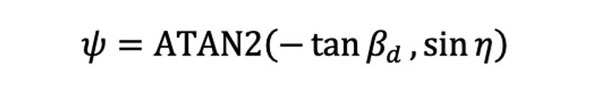
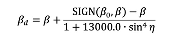
The RPP analysis has led to the development of a simple yaw model for the Block III satellites. For a Sun elevation angle β below β0 = 4.780 degrees, the yaw angle can be approximated with an RMS accuracy of about 8 degrees by the following formula: whereas
is a modified Sun elevation angle, SIGN(β0, β) a FORTRAN function returning the value of β0 with the sign of β, and η is the satellite’s argument of latitude with respect to orbit midnight. The agreement between estimated and modelled yaw angles is illustrated in Figure 5.
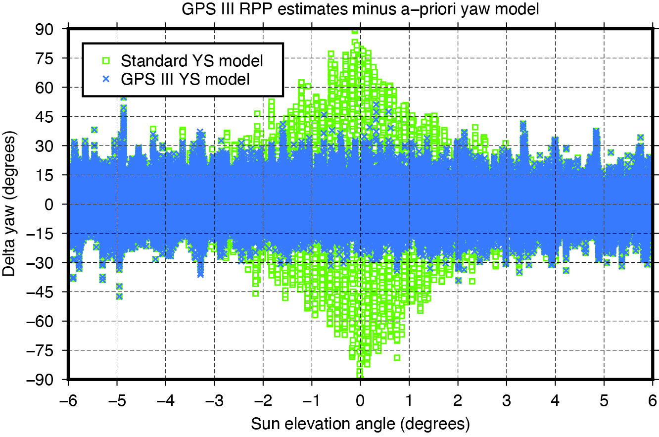
Figure 5: Differences between yaw angle estimates and yaw angle models.
Fourier Series for Radiation Force Modeling. The most critical component determining the shape of a GNSS satellite’s trajectory is SRP – the force caused by the impact of solar photons hitting the satellite’s surfaces. A satellite’s sensitivity to SRP can be characterized by the variation of the cross-sectional area to mass ratio (A/M) of the satellite body as it orbits Earth and the Sun. The greater the change in A/M, the higher the sensitivity. From this perspective, the Block III spacecraft can be considered the most sensitive in GPS history.
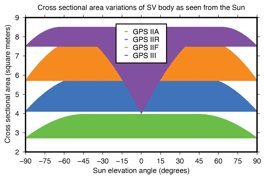
Based upon LM’s tried-and-true A2100 bus, the satellite is much more elongated than previous generations. With an estimated size of 7.5 meters squared, the X-side is almost twice as large as the Z-side. Depending on the elevation angle of the Sun relative to the orbital plane, the body’s cross-sectional area exposed to sunlight varies between 4.0 and 8.5 meters squared (See Figure 6). With a nominal on-orbit weight of approximately 2,160 kilograms, this results in a change of A/M of 0.0021 meters squared per kilogram. For comparison, the corresponding values for the previous GPS SVs are 0.0015 (IIF), 0.0017 (IIR), and 0.0013 (IIA) meters squared per kilogram.
Figure 6: Size of GPS satellite body’s cross-sectional area exposed to sunlight.
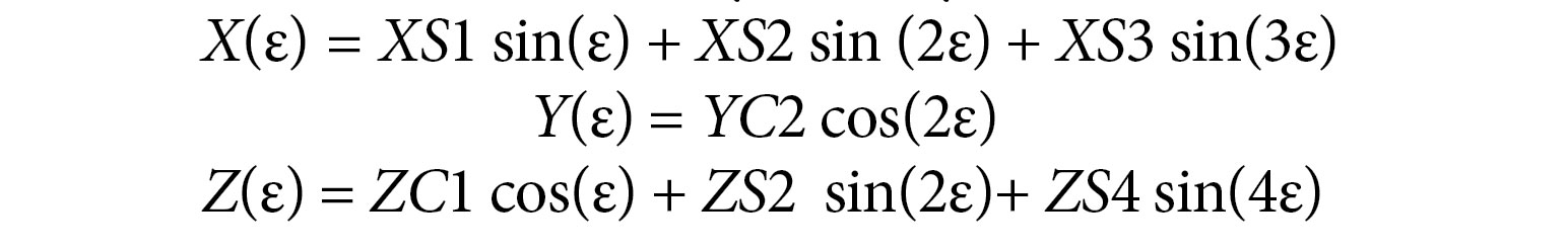
Given the size and shape of Block III spacecraft, an appropriate radiation force model is considered mandatory to achieve the highest orbit accuracy possible. With that said, we empirically derived a set of background force models for the first five GPS III satellites. Our approach rests on dynamical long-arc (9-day) fitting to precise orbit data spanning up to three years and the following low-order Fourier functions of the Earth-spacecraft-Sun angle ε to represent the radiation force in the satellite body-fixed system:
The Fourier coefficients (XS1, XS2, XS3, YC2, ZC1, ZS2 and ZS4) are iteratively adjusted together with initial epoch state, a constant Y-axis bias, and 1‐cycle per revolution along‐track parameters to best fit the orbit data in a least-squares sense. All individual 9-day arc solutions are rigorously combined on a normal equations level to form a robust set of Fourier model coefficients for each satellite or group of satellites.
ORBIT OVERLAP TESTS
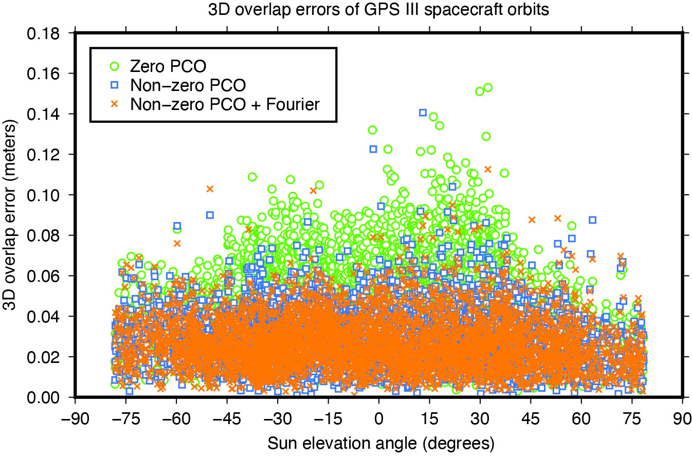
Figure 7: Impact of horizontal antenna PCOs and Fourier force model on day-boundary orbit overlap errors.
To investigate the effect of the transmit antenna PCOs and the Fourier force models on the satellite orbits, we use our ESA/IGS processing strategy to generate dynamic 24-hour-arc solutions spanning January 2020 to December 2022, first with zero PCO and the non-zero horizontal offsets from Table 1 and no a-priori radiation force model, then with the non-zero offsets and the additional Fourier model in the background. The direct comparison of the generated orbits reveals significant differences for the Block III satellites of about 0.1 meters (3D).
To demonstrate the improved performance of the non-zero offsets and the Fourier model, we take the orbits for successive days and look at the midnight epoch where they overlap. The difference in the orbit position, subsequently referred to as “overlap error,” gives us a worst case estimate of the satellite orbit accuracy. Comparison of the overlap errors provides evidence that the Block III orbits are much more accurate when using the non-zero rather than the zero X and Y PCOs. The overall 3D overlap RMS reduces from 49.5 millimeters (with zero PCOs) down to 32.3 millimeters (with non-zero PCOs). Results for the Sun elevation regions below 45 degrees, in particular, show significant improvement (see Figure 7).
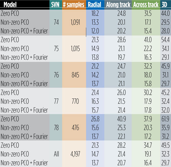
Use of the Fourier model has additional positive impact on the overlaps. Comparing the orbits produced with and without the a-priori radiation force model, we see a decrease in the 3D overlap error RMS from 32.3 to 29.7 millimeters averaged over all satellites. The orbit component that benefits most from both the improved antenna phase and the advanced force modeling is the one normal to the satellite orbital plane (across track). The SVs improving the most are SVN 75 and SVN 78, though significant improvements can be seen for all other satellites too (see Table 2).
Table 2: Day-boundary overlap RMS errors of GPS III spacecraft orbits in millimeters.
EMPIRICAL PARAMETER ESTIMATES
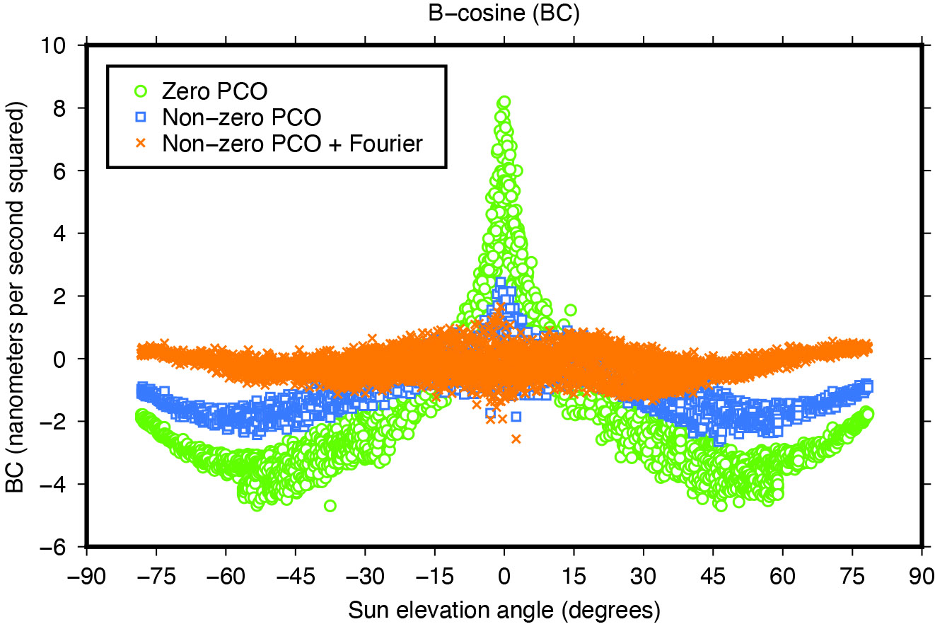
Another means of assessing the quality of spacecraft models is the size and variability of the five-plus-three empirical dynamic radiation pressure parameters that we still estimate on a daily basis for each GNSS satellite in addition to its a-priori force model. Introducing the non-zero PCO and Fourier models into the POD turned out to reduce the size of the empirical parameters and their dependency on the satellite-Sun geometry to a great extent as the example in Figure 8 demonstrates.
Figure 8: Impact of horizontal antenna PCOs and Fourier force model on empirical once-per-revolution acceleration term BC.
NARROW-LANE AMBIGUITY FRACTIONALS
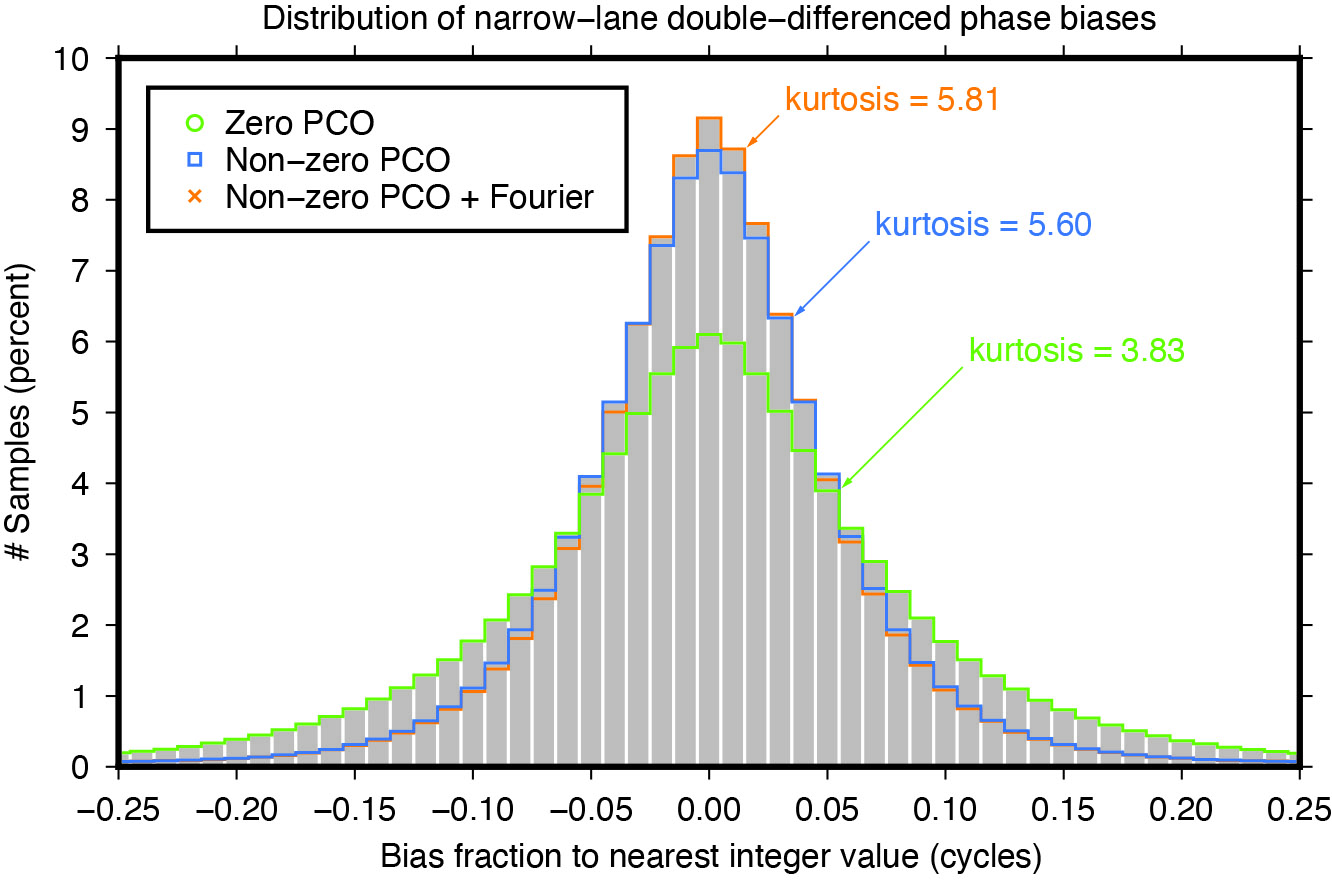
Integer ambiguity resolution — that is, resolving the unknown cycle ambiguities of double-differenced carrier-phase data to integer values — is considered indispensable to GNSS satellite POD and commonly results in a factor of two improvement in orbit precision. Of particular importance is the narrow-lane ambiguity that results from combining the carrier-phase measurements from a pair of GNSS frequencies. One of the intermediate steps in the ambiguity resolution algorithm is the fixing of the double-differenced narrow-lane ambiguities to integer values. For reliable fixing, the fractional part of the difference between the integer and decimal (float) values should be as close as possible to zero and follow a symmetrical distribution. The “tailedness” of the distribution curve may be characterized by its kurtosis — the larger the kurtosis, the fewer values are in the tails of the distribution and the more peaked is the distribution. In other words, the larger the kurtosis, the closer the “fractionals” cluster around zero, the more ambiguities can be resolved with higher confidence, and the more accurate the resolved solution. Moreover, as satellite orbit and antenna phase center errors do not cancel out completely through double-differencing, the narrow-lane kurtosis may also be considered as an indicator for the accuracy of the satellite force and phase center models that were used. The results in Figure 9 show that the non-zero horizontal PCOs bring a major improvement and that the Fourier force model does give some additional benefit.
Figure 9: Impact of horizontal antenna PCOs and Fourier force model on fractional part of double-differenced narrow-lane ambiguities.
CONCLUSIONS
Adding a new GNSS satellite type to high-precision multi-GNSS solutions requires detailed knowledge and understanding of the satellite type. Key issues are the transmit antenna phase center parameters, the satellite’s attitude, and the radiation pressure forces acting on its surfaces.
In this article, improved antenna phase center, attitude, and radiation pressure models for the current series of GPS Block III spacecraft have been developed using multiple years of in-flight orbit and tracking data. A number of internal metrics such as post-fit carrier-phase residuals, day-boundary orbit differences (overlaps), empirical acceleration parameters, and carrier phase ambiguity statistics have been used to gauge the models’ performances. Overall, the results underscore the importance of the models for GPS III orbit determination. This applies primarily to the radiation force and the antenna phase center model, or more precisely, the horizontal (X and Y) offsets of the phase center model whose existence has been neglected for years in the analysis of GPS III data.
Comparison of the overlap statistics suggest that orbits generated based upon updated (non-zero) phase center corrections and ESA/ESOC’s new (Fourier-based) radiation pressure model in the background are better by almost a factor of two. The average overlap RMS errors calculated across all current Block III SVs and for each orbital component (radial, along track and across track) dropped from 21 , 28 and 35 millimeters down to 14, 21 and 16 millimeters, respectively.
More relevant when it comes to processing GPS data recorded on board low-flying satellites such as Sentinel-6 Michael Freilich or Jason-3, is the extension of the current IGS Block III antenna PCV model beyond a 14-degree boresight angle. After applying the extended PCV corrections, we reduced Block III carrier-phase residuals by 20% with no or few systematic signatures remaining, unlike the residuals produced with the current IGS antenna model. The IGS is strongly encouraged to adopt the Block III PCV extension into their antenna model to continue to support GPS-based POD of low-Earth-orbiting satellites.
For further details on ESA/ESOC’s solar radiation pressure modeling approach, see our paper “GPS III Radiation Force Modeling” presented at the IGS 2022 Virtual Workshop: click here.
FLORIAN DILSSNER is a satellite navigation engineer in the Navigation Support Office at the European Space Operations Centre (ESOC) of the European Space Agency (ESA), Darmstadt, Germany. He earned his Dipl.-Ing. and Dr.- Ing. degrees in geodesy from the University of Hannover, Germany.
TIM SPRINGER has been working for the Navigation Support Office at ESA/ESOC since 2004. He received his Ph.D. in physics from the Astronomical Institute of the University of Bern in 1999.
FRANCESCO GINI is a satellite navigation engineer in the Navigation Support Office at ESA/ESOC. He received his Ph.D. in astronautics and space sciences from the Centro di Ateneo di Studi e Attività Spaziali at the University of Padova in 2014.
ERIK SCHÖNEMANN is a satellite navigation engineer in the Navigation Support Office at ESA/ESOC. He earned his Dipl.-Ing. and Dr.- Ing. degrees in geodesy from the University of Darmstadt, Germany.
WERNER ENDERLE is head of the Navigation Support Office at ESA/ESOC. He holds a doctoral degree in aerospace engineering from the Technical University of Berlin, Germany.
“Seen & Heard” is a monthly feature of GPS World magazine, traveling the world to capture interesting and unusual news stories involving the GNSS/PNT industry.
Image: Apple
Apple Products Meet Accuracy with GPS
Apple launched the Ultra Watch, which contains a dual-frequency GPS antenna that can receive L5 signals, as well as the iPhone 14, which features a dual-band GPS receiver combining the L1 and L5 signals. The company is also harnessing signals from more than 70 satellites to boost the accuracy of its services such as SOS alerts and alerting emergency responders, per The National News. The dual-frequency abilities of the new products provide accurate location for calculating distance, pace and routes. The L5 signals also are a critical component of Apple’s health and safety features, providing more accuracy than in previous products.
Wildlife researchers in Key Largo, Florida, accidently discovered a way to locate and eradicate invasive Burmese pythons, per WFLA News Channel 8. The team of researchers were observing racoons and possums that were fitted with tracking collars to note their behavior. After months of observation, a possum collar sent a mortality signal due to lack of movement. To the researchers’ surprise, the collar then started moving again. They later discovered the possum had been eaten by a python. While this was not the intent of the team’s research, they proved this could be an effective way to lower the increasing population of the invasive python species.
Scientist Liu Shaochuang and his team have used satellite remote-sensing technology to study and track wild camels. Shaochuang studies the interrelationship between endangered animals and their environments, which may help protect the species against climate change. To track a camel, Shaochuang attaches a GNSS-enabled collar, which transmits the camel’s location every day. The short message function is provided by China’s BeiDou satellite system, which transmits and receives signals in real time. Based on the data, Shaochuang and his team can observe migratory paths, living environments and possible threats.
Image: Screenshot of CNN video
Former South Carolina Attorney Convicted with Location Data
On March 3, Alex Murdaugh was convicted of killing his son Paul Murdaugh and wife Maggie Murdaugh. With limited evidence, the prosecution used a phone video and vehicle navigation data to prove Alex’s guilt. During the trial, Alex claimed he was visiting his mother during the time the murders took place. However, General Motors OnStar data accessed by investigators from his Chevrolet Suburban contradicted the alibi, putting Alex at the scene of the crime during the time of the murders. Plus, in a smartphone video taken by Paul that night, Alex’s voice could be heard, placing him at the scene.
Lt. Col. Robert O. wray commands the 2nd Space Operations Squadron (2 SOPS), which operates GPS around the clock supplemented by members of the 19th Space Operations Squadron (19 SOPS). (Credit: U.S. Space Force photo by Dennis Rogers)
Exclusive GPS World interview with the commander of the unit that operates the GPS constellation
The entire Global Positioning System constellation comprised of 38 satellites — with its billions of users and myriad military, commercial, consumer and scientific applications — is controlled from one room in a gray office building on a small military base about nine miles east of Colorado Springs, Colorado. The base is Schriever Space Force Base (SFB) and the room is the “operations floor” of the GPS Master Control Station (MCS). It is staffed by members of the 2nd Space Operations Squadron (2 SOPS), an active-duty unit of the U.S. Space Force, supplemented by members of the 19th Space Operations Squadron (19 SOPS), a unit of the U.S. Air Force Reserve. The two squadrons are known collectively as “Team Blackjack.”
Lt. Col. Robert O. Wray is the commander of 2 SOPS and of those 19 SOPS members assigned to the MCS. On March 16, at Schriever SFB, Wray spoke at length with GPS World’s editor-in-chief, Matteo Luccio, about the training and duties of his team members, the challenges they face, and what brought him to his current assignment. He then gave Luccio a tour of the MCS and introduced him to each of the 10 people on duty. At any given time, eight of these operators are military personnel and two are civilian contractors. They receive feeds from a worldwide network of monitor stations and ground antennas, including telemetry from the satellites, that enable them to precisely monitor the satellites’ orbits and the state of their systems. The operators upload data and commands to the satellites around the clock to keep the constellation fine-tuned and respond to changing circumstances.
An abridged version of the interview will appear in the May issue of GPS World. A longer version will appear here on May 1.
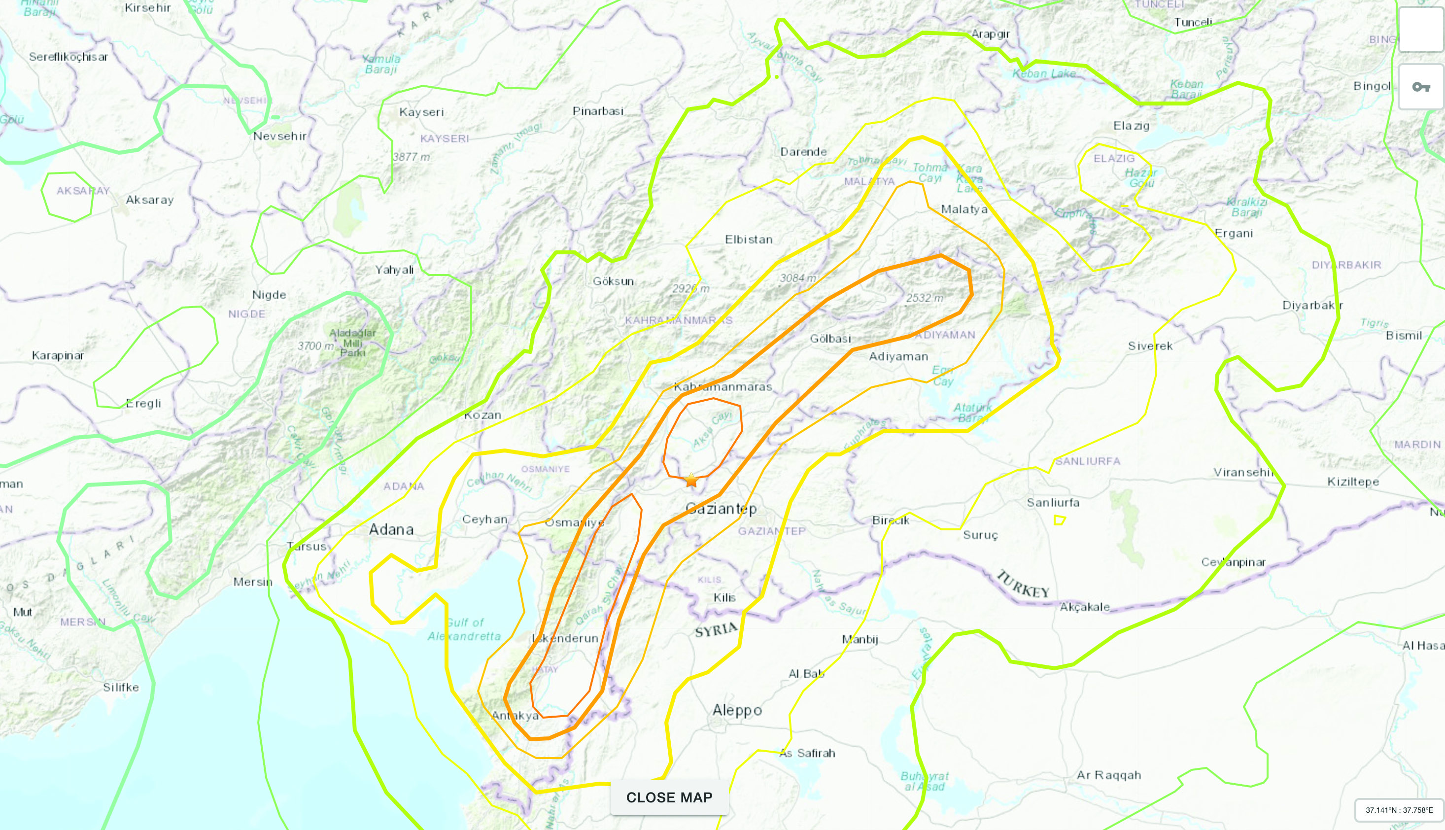
The Mw 7.8 and Mw 7.5 Kahramanmaraş Earthquake Sequence struck near Nurdağı, Türkiye, on Feb. 6. It collapsed several buildings and has claimed more than 50,000 lives. The impact of the initial earthquakes was very severe, but to make matters worse, later in February, a Mw 6.4 tremor struck near Antakya, a city near Türkiye’s border with Syria. This created further damage to infrastructure and claimed more victims.
Image: Screenshot of video from NBC News
The Specifics
The United States Geological Survey reports that the earthquake resulted from strike-slip faulting at shallow depths. The earthquake sequence displaced numerous fault segments within the East Anatolian Fault zone. Early estimates indicate about 185 miles of fault length ruptured. Parts of the North Anatolian Fault shifted 10 feet, while segments of the East Anatolian Fault slid more than 30 feet.
Historic Site Suffers
Gaziantep Castle dates back to the second millennium B.C. It has been used in many capacities throughout history, and more recently, stood as a museum for visitors to learn about its rich history. The castle was reduced to rubble in the earthquake. Other historical sites that sustained damage include the Yeni Mosque and the ancient city of Aleppo in Syria.
Image: Screenshot of CNN video
Earth Opens Up
The earthquake destroyed cities all over Türkiye and northern Syria, but they are not the only areas that suffered dramatic effects. A verdant olive grove in Tepehan, Hatay Province, Türkiye, was completely divided when the ground split, creating a 984-foot-long valley in the middle of the grove. The valley is more than 130 feet deep and has created issues for the 7,000 people that inhabit the area.
LEUVEN is a city with a bustling atmosphere full of shops, restarants and more. The culturally rich city is inhabited by more than 100,000 people — 60,000 of them being students. (Image: lavio Vallenari/iStock Unreleased/Getty Images)
Follow the cobblestone road through the narrow streets of Leuven, Belgium, and you will likely come out to the medieval-looking main square surrounded by a gothic church, lavishly architected restaurants and the breathtaking city hall, ornamented by hundreds of historical statues. Don’t let it fool you — this culturally rich city produces some of the most cutting-edge technology today, right next to the world-famous Stella Artois beer factory. In fact, Leuven was named as the European Capital of Innovation by the EU Council in 2020.
In this city is the headquarter of Septentrio, a manufacturer of high-precision GNSS positioning solutions and a fast growing company. Septentrio’s recently launched products, including the compact mosaic-X5 GNSS module and AsteRx-i3 GNSS/INS OEM board, are further fueling its growth and market share gains.
There is an intricate link between the city of Leuven, its university, and the high-tech industry that results in such a bubbling cauldron of innovation. The powerful synergy between the university and the city makes Leuven unique. Established in 1425, the Catholic University of Leuven (KU Leuven) is one of the oldest universities in Europe. It uniquely combines a very high standard of education with openness and inclusiveness.
This combination of excellence and inclusiveness is rather unique, as most top-quality universities have a more exclusive approach. While ranked as one of the top universities by Reuters, KU Leuven is accessible to students from around the world and actively collaborates with industry players in the surrounding area. At the same time, Leuven’s local government enables and supports the university with housing, student life, events, grants and more. With more than 150 nationalities living in Leuven, the city is a hotspot of diversity in terms of cultural background, experience and talent.
SEPTENTRIO headquaters is nestled near KU Leuven University — one of Europe’s top sources for talent in the areas of signal processing and advanced algorithms. (Image: Matteo Luccio)
As early as 1972, the university established the Leuven Research and Development Tech Transfer office, to valorize know-how. Since then, hundreds of spin-offs have emerged and settled in the Leuven area, including the Haasrode Research-Park, where 12,000 professionals work today and where Septentrio is situated.
Another important player tightly linking KU Leuven and the industry is the IMEC research center. IMEC is the world’s largest independent research center dedicated to semiconductor technology, housing the most advanced wafer fab equipment and employing more than 5,000 researchers. It has more than 4,000 active patents today. As the chairman of its board, I can personally vouch for IMEC as a center of excellence, with the highest standards for quality, fueled by the most talented post-graduates of KU Leuven and professionals from all around the world. For example, IMEC has recently built a new clean room, totaling 12,000 square meters, operating 24/7 to produce next-generation integrated circuit technology and nanoelectronics. Once a new idea or technology is identified, it is sometimes spun-off as a company. That’s exactly how Septentrio started 22 years ago, and it still works very closely with IMEC as a partner and a source of talent for semiconductor and hardware development.
Another key partner of Septentrio is the European Space Agency (ESA), which enables us to be at the forefront with the latest GNSS technology. From the very inception of Galileo, the European GNSS constellation, ESA has given us the opportunity to be involved as the developer of the Test User Receiver, which acquired the very first signals. Septentrio has also been providing reference receivers for the ground segment of the European Geostationary Navigation Overlay Service (EGNOS), which is Europe’s regional satellite-based augmentation system (SBAS), aimed at providing higher accuracy positioning for airplanes. Working with ESA as a strategic partner allowed us to gain the expertise and insights needed to be the first to market with many key technologies, for example the Open Service Navigation Message Authentication (OSNMA) anti-spoofing authentication on the mosaic module.
Our strategic partnership with ESA and close collaboration with the IMEC semiconductor technology hub has enabled Septentrio to produce mosaic-X5. This compact module is one of the highest performing and resilient GNSS receivers on the market. It is used in a wide array of applications, especially where the position is mission-critical. Examples include a wide variety of autonomous devices, including UAVs that benefit from mosaic’s lightweight and low-power design. The mosaic-H provides accurate heading and is used in applications such as faster set-up and directing of 5G telecom antennas
In short, Leuven offers us an exciting and innovative working environment, as we continue to push out the limits of technology to deliver better solutions to our customers.


