A roundup of recent products in the GNSS and inertial positioning industry from the April 2023 issue of GPS World magazine.
TIMING
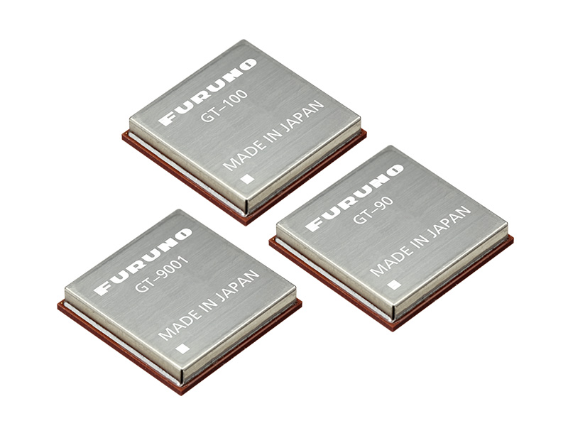
Global Timing Module
Supports L1 and L5 GNSS signals
GT-100 is compatible with all GNSS constellations. The GT-100 realizes high robustness and standard of time accuracy and stability. The GT-100 features advanced multipath mitigation, anti-jamming and anti-spoofing as well as short-term holdover, ensuring superior performance even if L1 or L5 are jammed. The module delivers nanosecond precision for 5G wireless systems, radio communications systems, smart power grids and grand master clocks. Along with the GT-100, GT-9001 and GT-90 achieve a level of time stability of 4.5ns (1σ) and offer superior features and performance.
Furuno, furuno.com
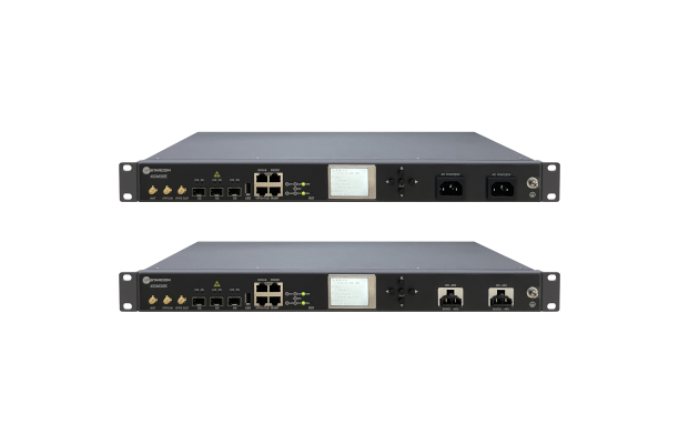
PTP Grandmaster
Designed for mobile networks
The SyncRing XGM30E precision time protocol (PTP) grandmaster is designed for mobile networks and other applications requiring accurate time and frequency synchronization. It is an addition to the SyncRing line of network synchronization equipment. The SyncRing XGM30E is an indoor PTP grandmaster offering echo time accuracy of more than ±40 ns, which can meet the stringent timing requirements of demanding applications, including 4G and 5G networks. The clock complies with the PTP IEEE 1588-2008 standard, supporting major ITU-T frequency and phase and time profiles. SyncRing XGM30E supports synchronous Ethernet (SyncE) output on all service interfaces for accurate frequency synchronization, and SyncE input for enhanced time holdover operation during GNSS outages. The grandmaster includes an indoor rack-mount design and power supply redundancy with AC or DC built-in options and has flexible management options. The SyncRing XGM30E is available now.
UTStarcom, utstar.com
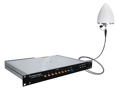
Copper-Free Data System
For precise timing synchronization for high-performance networks
The GNSS and Power over Fiber GPSoF System receives, transmits and expands GNSS timing signals for the purpose of timing synchronization in data centers, central offices, distributed antenna systems or enterprise applications. It enables greater distances between the radio frequency source and the receiver system. It is also immune to RFI, EMI and EMP, contains remote control and monitoring via a web interface, and supports infrastructure installation due to direct GNSS signal evaluation.
Huber+Suhner, hubersuhner.com
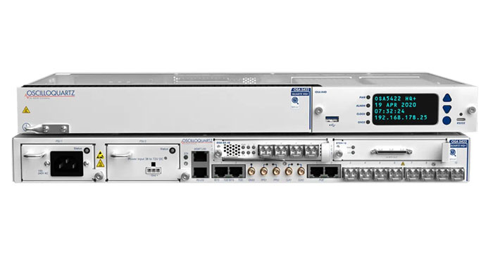
M-Code Device
With advanced timing for military applications
The OSA 5422 grandmaster clock meets key requirements of military networks by providing advanced positioning, navigation and timing (PNT) capabilities and improved resilience. The OSA 5422 grandmaster clock is integrated with a highly reliable M-code receiver, which meets stringent frequency and phase synchronization needs. The device is equipped with multi-band, multi-constellation GNSS receivers for when M-code is not available. The OSA 5422 also has long holdover and precision time protocol backup, which enables it to maintain accurate timing even in the event of M-code disruption. The OSA 5422 supports legacy interfaces such as BITS and IRIG and features eight field-upgradable 10G bit/s ports and 1G bit/s interfaces. The device is suitable for most demanding military edge applications.
ADVA, adva.com; Brandywine Communications, brandywinecomm.com
AUTONOMOUS
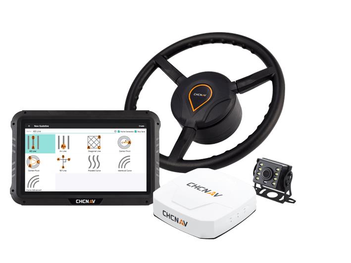
GNSS RTK Steering System
Suitable for agriculture applications
The NX510 SE Auto-Steer is an automated steering system that retrofits several types of new and old farm tractors and other vehicles. It can be connected to local real-time kinematic (RTK) networks or GNSS RTK base stations. NX510 SE is a guidance controller powered by multiple corrections sources and five satellite constellations: GPS, GLONASS, Galileo, BeiDou and QZSS. It has a built-in 4G and UHF modem that connects to all industry-standard differential GPS and RTK corrections to achieve centimeter-accuracy steering. NX510 SE contains GNSS and inertial navigation system terrain compensation technology, which maintains high accuracy in challenging environments and terrain. This makes NX510 SE suitable for ditching, planting and harvesting applications. In addition, AgNav multilingual software, operating on a 10.1 in industrial display, supports multiple guideline patterns that include AB line, A+ line, circle line, irregular curve and headland turn.
CHC Navigation, chcnav.com
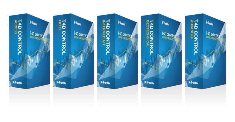
Module for Rail Monitoring
For automated and semi-automated rail monitoring
The T4D Rail Module enables simple data collection and reduces office work required to automate movement detection for rail monitoring projects. The T4D software offers four main elements for automated monitoring: sensor management and data integration for GNSS; total station, geotechnical, vibration and environmental sensors; geodetic processing and adjustments for accurate results; analysis and visualization through several tools that provide real-time updates to support in-depth analysis and data presentation; and alarming and reporting. The T4D Rail module enables integration of rail as-builts collected with the Trimble GEDO system or with a track measuring bar paired with the Trimble Access Gauge Survey app. It also can automate calculations for track geometry parameters, generate analysis charts, and trigger alarms. The T4D software is offered in five editions to fit various project requirements. The editions include T4D Access, T4D Field, T4D Intermediate, T4D Geotechnical and T4D Advanced. T4D Access and T4D Advanced are the two editions that support the add-on Rail Module.
Trimble Geospatial, geospatial.trimble.com
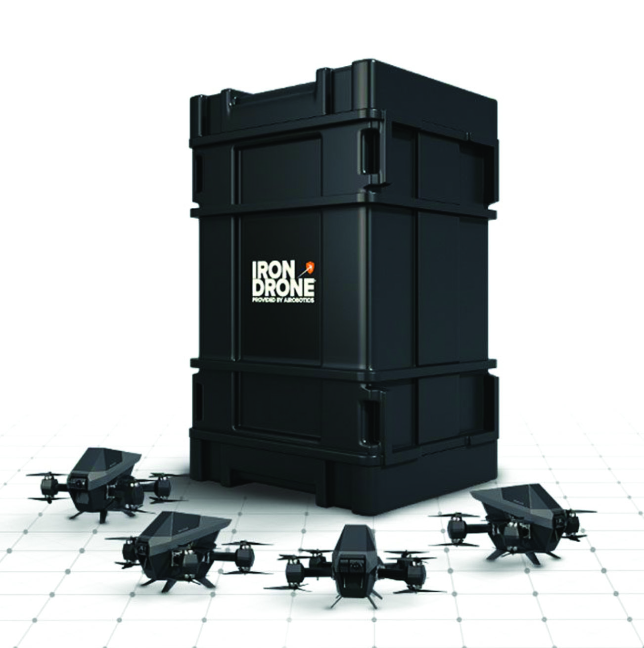
C-UAV Device
Anti-UAV protection device
The Iron Drone system is an advanced counter-UAV device, designed to defend against hostile drones in complex environments with minimal damage. Iron Drone is an automated intercepting system designed to eliminate small drones without using GPS or radio frequency jamming. The Iron Drone system is launched from a designated pod and flies autonomously towards targets under radar guidance. It identifies the target using computer vision capabilities. The intercepting UAV follows the target then uses a net and a parachute to incapacitate it, capture it and lower it to the ground.
Airobotics, airoboticsdrones.com
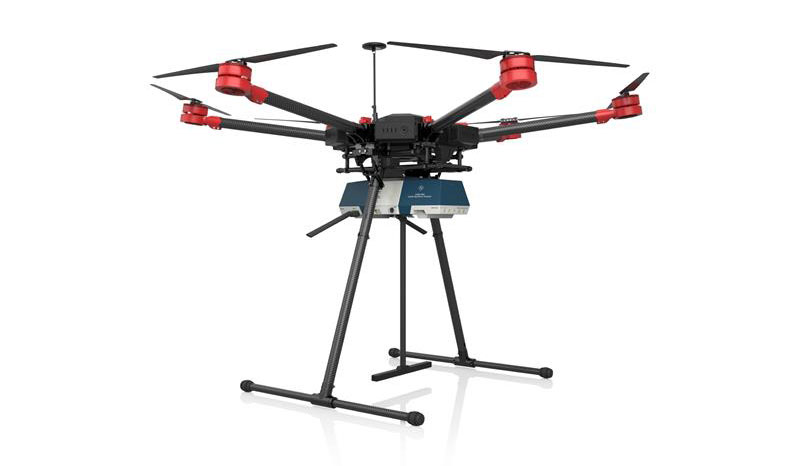
Drone-based analyzer
For UAV inspections
EVSD1000 VHF/UHF nav/drone analyzer provides highly accurate UAV inspection of terrestrial navigation and communications systems. The EVSD1000 VHF/UHF nav/drone analyzer is a signal-level and modulation analyzer for medium-sized UAVs. It features measurements of instrument landing systems, ground-based augmentation systems and VHF omnirange ground stations. The mechanical and electrical design is optimized for UAV-based, real-time measurements of terrestrial navigation systems with up to 100 measurement data sets per second. The analyzer provides high-precision signal analysis in the frequency range from 70 MHz to 410 MHz. This also includes the needed measurement repeatability to ensure that results from UAV measurements can be compared to flight and to ground inspections in line with ICAO standards. The EVSD1000 VHF/UHF nav/drone analyzer reduces runway blocking times, provides necessary measurement repeatability and offers measurement precision and GNSS time and location stamps. While streaming measurement data during a drone flight via the data link to a PC on the ground, the analyzer can also buffer data internally to ensure no results are lost if the data link is lost.
Rohde & Schwarz, rohde-schwarz.com
SURVEYING & MAPPING
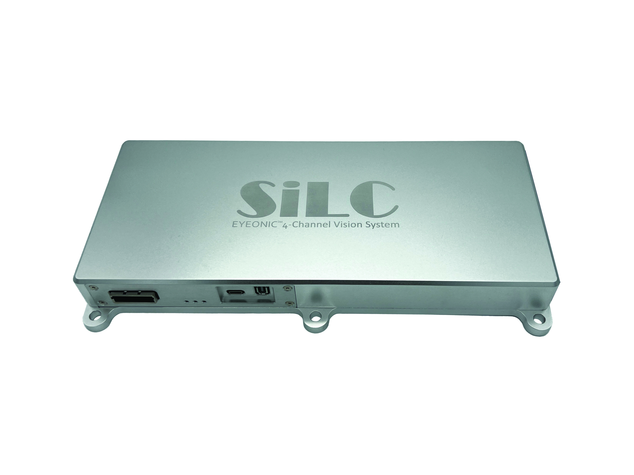
Coherent Vision Solution
Suitable for advanced products
The Eyeonic Vision System is a frequency-modulated continuous wave lidar solution, which delivers high levels of vision perception to identify and avoid objects with low latency. At the core of the system is a fully integrated silicon photonics chip. It provides more definition and precision than legacy lidar solutions, with roughly 10 milli-degree of angular resolution coupled with millimeter-level precision. These features enable this solution to measure the shape and distance of objects with high-precision and at a large distance. The system combines the Eyeonic Vision Sensor and a digital processing solution based on a powerful field-programmable gate array. The flexible architecture enables synchronization of multiple vision sensors for unlimited points per second. The compact, powerful, vision solution is suitable for autonomous vehicles, smart cameras, robotics and other advanced products. It is available now. Pricing varies depending on configuration.
SiLC Technologies, silc.com
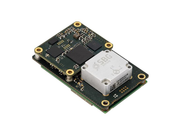
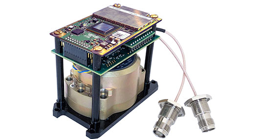
GNSS-Aided INS
Easily integrated with lidar or other third-party sensors
Quanta Plus is a GNSS-aided inertial navigation system (INS). The device combines a MEMS inertial measurement unit (IMU) with a resilient GNSS receiver to get reliable position and attitude, as well as providing real-time kinematic (RTK) fixes. Quanta Plus includes motion profiles, which enable users to optimize the sensor parameters to suit different use cases. The built-in precise time protocol server ensures sub-microsecond synchronization with external devices such as lidar. The device also has a built-in datalogger, Ethernet interface for easy integration, and a web configuration interface for simple setup and control. The INS can be integrated with Qinertia, SBG System’s post-processing software. Qinertia improves the performance of acquired data during a mission using reliable RTK corrections from a wide range of continuously operating reference station networks, or by importing base-station data during the process. Quanta Plus also improves the accuracy of the position and attitude using forward and backward processing and by integrating a tight coupling between GNSS and IMU data.
SBG Systems, sbg-systems.com
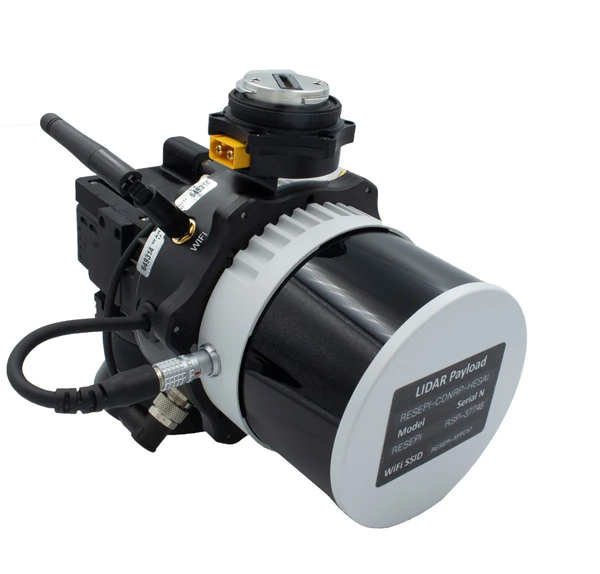
Survey Laser
Suitable for remote-sensing applications
The Resepi Hesai XT32 laser is designed for accurate remote-sensing applications. It can be used with commercially available lidar scanners, including Velodyne, Quanergy, Ouster, RIEGL, LIVOX and Hesai, as well as with UAVs. Resepi is completely modular, so users have full control for customization. The remote-sensing device uses a GPS-aided inertial navigation system with a NovAtel RTK/PPK single- or dual-antenna GNSS receiver, integrated with a Linux-based processing platform. It also comes with a 2 TB USB memory drive and has an embedded Wi-Fi cellular modem. Resepi has 3 cm to 5 cm point-cloud accuracy and can reach heights of more than 200 m above ground level. It is compatible with most UAV models; however, it is typically used with DJI M300, DJI M210 or DJI M600 models. The device is suitable for scanning and mapping, precision agriculture with lidar, simultaneous localization and mapping algorithm development, utility inspection and construction site monitoring. Resepi-supported software includes Hexagon NovAtel, PCPainter and PCMaster.
Inertial Labs, inertiallabs.com
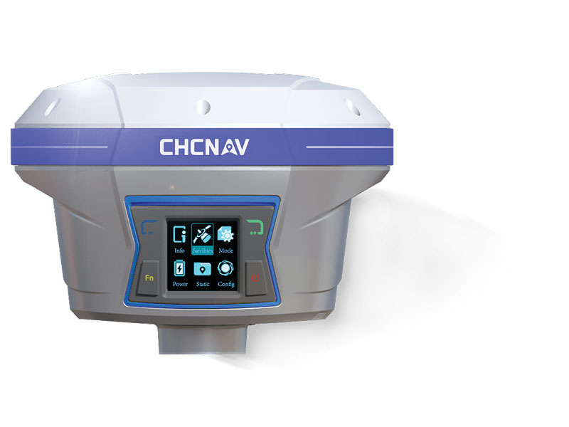
IMU-RTK GNSS Receiver
Provides robust and accurate positioning
The i90 GNSS receiver combines a GNSS real-time kinematic (RTK) engine, a high-end inertial measurement unit (IMU) sensor and advanced GNSS tracking capabilities to increase RTK availability and reliability. The embedded 624-channel GNSS receiver is compatible with GPS, GLONASS, Galileo and BeiDou signals. The i90 GNSS combines high-end connectivity modules: Bluetooth, Wi-Fi, NFC, 4G and a UHF radio modem. The internal UHF radio modem allows long-distance base-to-rover surveying up to 5 km. The built-in IMU ensures interference-free and automatic pole-tilt compensation in real time. An accuracy of 3 cm is achieved with pole-tilt range of up to 30°. The i90 GNSS receiver is suitable for construction and land surveying projects.
CHC Navigation, chcnav.com
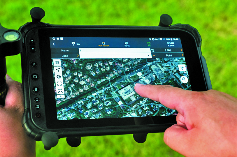
Field Application
For Android devices
LandStar8 is designed to be flexible and user-friendly for surveying and mapping tasks. It is versatile, modular and customizable for topographic tasks such as surveying, stake out, cadastral, mapping and geographic information systems (GIS). Building on the legacy of LandStar7, the LandStar8 provides features such as a refined user interface, streamlined workflows, faster operation, and integrated cloud services. Cloud connectivity is built in for backup, data storage or remote technical support. LandStar8 has a simple and intuitive layout with large map windows and sharp graphics. Users can hide features they rarely use and display only those they need. They also can copy coordinate settings, control and staking points from another handheld controller by scanning a QR code. Projects can be edited and sorted by history and attributes. Custom coordinate systems, geoid models and coding libraries can be updated at any time by using resource packages. LandStar8 also features a terrain calibration wizard designed for non-expert users.
CHCNAV, chcnav.com

Survey Rover
For accurate, survey-grade aerial mapping and photogrammetry
SmartSurveyor facilitates accurate, survey-grade aerial mapping and photogrammetry without the need for a connection between a camera shutter and a GNSS receiver. The fully compact, handheld aerial mapping survey rover is compatible with DJI Mavix 2 and 3 series and Phantom 4 Pro UAVs. The design is dissimilar from other UAV mapping systems in that it works from a UAV or smartphone and with two or more ground control points (GCPs) while using an ultra-matching technique. Once SmartSurveyor captures data, all photos and the GNSS file are uploaded to a PC and analyzed through the Agisoft UltraMatch workflow to confirm their accuracy before they are exported. Data can be managed in the cloud or on a local PC using software designed by MapSender. Additionally, this mapping tool works in tandem with the AllDayRTK subscription GNSS network service so that collected data can be uploaded to Tokara to remotely manage a project.
Position Partners, positionpartners.com
OEM
NB-IoT Industrial Module
Complete with GNSS geo-location capabilities
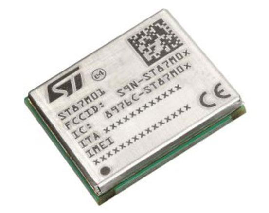
The ST87M01 is a fully programmable, certified LTE Cat NB2 NB-IoT industrial module that covers worldwide cellular frequency bands and integrates advanced security features. The ST87M01 is an integrated native GNSS receiver with multi-constellation access, which ensures enhanced and accurate localization. The module has a diminutive 10.6 mm x 12.8 mm land grid array footprint, making it suitable for applications where a small form factor is key. The STM8701 offers flexibility for product developers, presenting a fully programmable internet of things (IoT) platform enabling users to embed their own code into the module for simple applications. A variety of protocol stacks are available to handle popular IoT use cases. It targets wide-ranging IoT applications that require ultra-reliable low-power wide-area network connectivity and has ultra-low power consumption with less than 2 µA in low-power mode and transmit output power up to +23 dBm. Suitable applications for the module include smart metering, smart grid, smart building, smart city and smart infrastructure applications, as well as industrial condition monitoring and factory automation, smart agriculture and environmental monitoring. The module also can be combined with a separate host microcontroller, permitting many more use cases.
STMicroelectronics, st.com
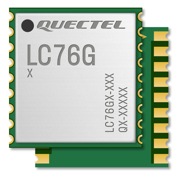
GNSS Module
Designed for battery-operated, ultra-low power GNSS devices
The LC76G module is a compact, single-band, ultra-low power GNSS module that features fast and accurate location performance. The module can concurrently receive and process signals from the GPS, GLONASS, BeiDou, Galileo and QZSS constellations. The LC76G has an internal surface acoustic wave filter and integrated low-noise amplifier, which can be connected directly to a passive patch antenna and provides filtering against unwanted interference. With a compact size of 10.1 mm × 9.7 mm × 2.4 mm, the footprint of the LC76G is compatible with other industry solutions, as well as Quectel’s legacy L76 and L76-LB modules. The LC67G is designed for battery-operated, ultra-low power GNSS devices, such as wearable personal trackers, wildlife and livestock tracking, toll tags, portable container trackers, as well as several traditional markets such as shared mobility and low-cost asset trackers.
Quectel Wireless Solutions, quectel.com
Inertial Navigation System
Incorporates NovAtel and Honeywell technology
The INS-DH-OEM utilizes a dual-antenna NovAtel GNSS receiver and a Honeywell HG4930-CA51 inertial measurement unit (IMU). The INS-DH-OEM contains Inertial Labs’ on-board sensor-fusion filter, navigation and guidance algorithms, and calibration software. The INS-DH-OEM has three axes, a full operational temperature range, advanced MEMS accelerometers and new-generation tactical-grade MEMS gyroscopes to provide accurate position, velocity, heading, pitch and roll. It is small and lightweight, measuring 85.5 mm x 67.5 mm x 52.0 mm and weighing 280 g. The dual-antenna NovAtel GNSS receiver is operational with GPS, GLONASS, Galileo, BeiDou and QZSS constellations. The INS-DH-OEM is compatible with most commercially available lidars including Velodyne, Riegl and Faro. The algorithms are suitable for different dynamic motions of vessels, ships, helicopters, UAVs, gimbals and land vehicles.
Inertial Labs, inertiallabs.com
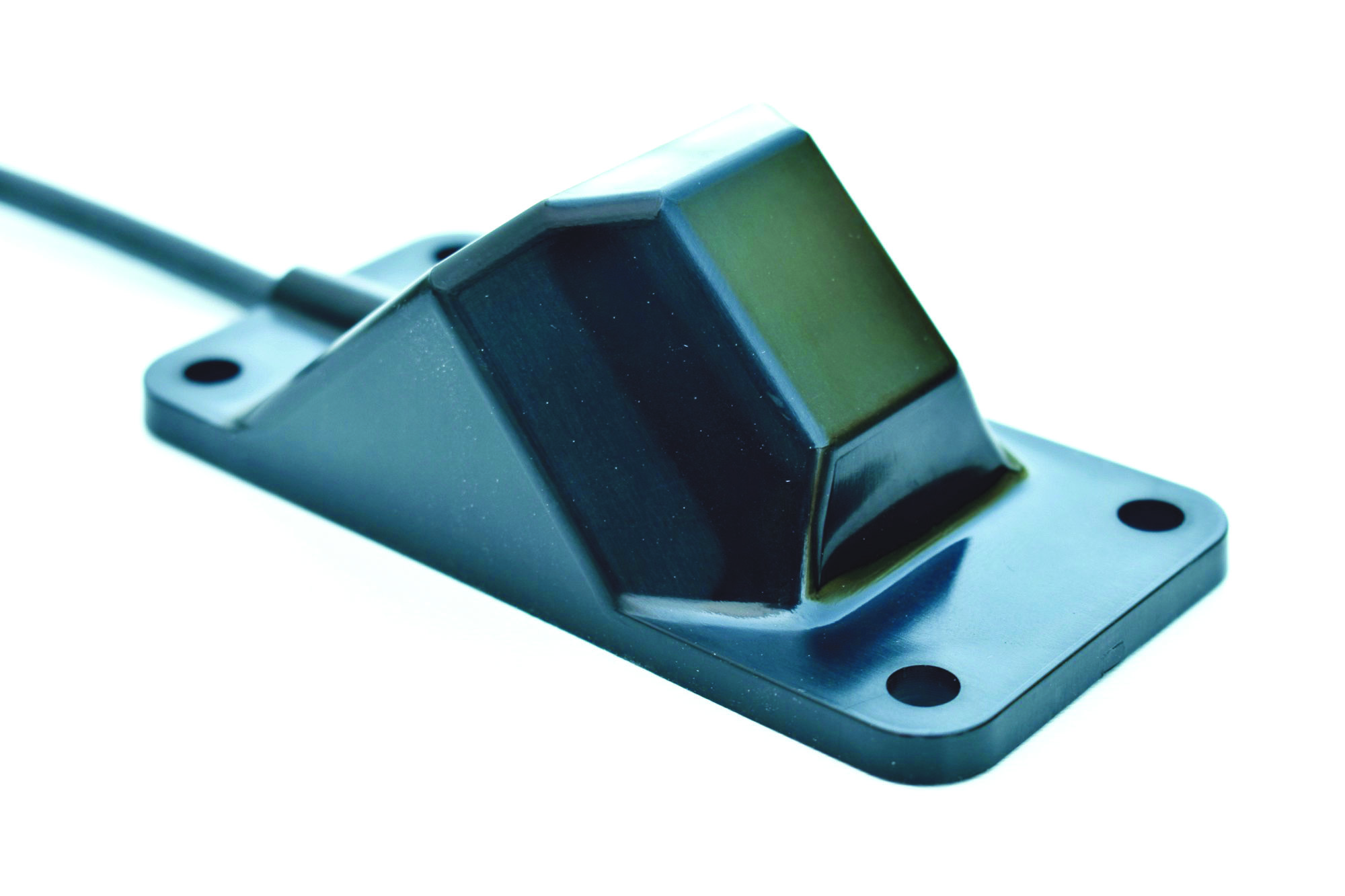
Speed Sensor
Multi-use sensor for workflow
The Speed Wedge MKII is a true-ground speed sensor and active motion detector for moving objects, based on radar doppler technology. This sensor is suitable for use in indoor and off-highway vehicles, conveyor belts, material flow and open channel water surface flow. The sensor contains a dead-reckoning system component for inertial measurement units and integrated management systems (IMS) in GPS/GNSS-denied environments such as in tunnels and underground mining operations. It also features sensor fusion with GNSS and IMS improving positioning accuracy, quality and reliability. Speed Wedge MKII deploys a radar front-end with planar antennas continuously emitting electro-magnetic waves at 24 GHz. It is designed for contactless measurement of speed and distance travelled independent on wheel/drive slip. For demanding applications Speed Wedge MKII is sealed and potted in a rugged encasing. Speed Wedge MKII is available in variants with pulse, serial RS232 and CAN-Bus output. High-speed up to 200 km/h is available.
MSO, mso-technik.de/home-en.html
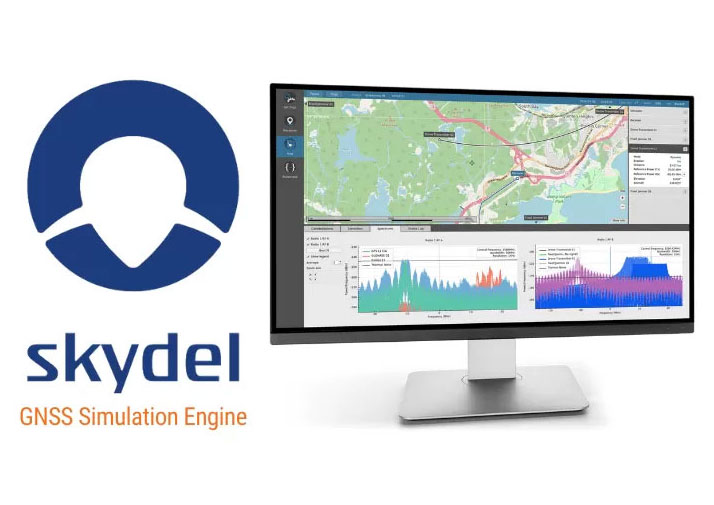
GNSS Simulations Software
For simulation and testing needs
Skydel GNSS simulation software can now generate more than 500 simulated satellite signals. This platform is suitable for GNSS users, experts and manufacturers, as well as users needing a low-Earth-orbit-capable simulation system. Skydel contains a feature that includes multi-constellation and multi-frequency signal generation, remote control from user-defined scripts, and integrated interference generation. In addition to generating a high channel and satellite count, Skydel also can produce navigation warfare signals without any additional hardware.
Orolia, orolia.com
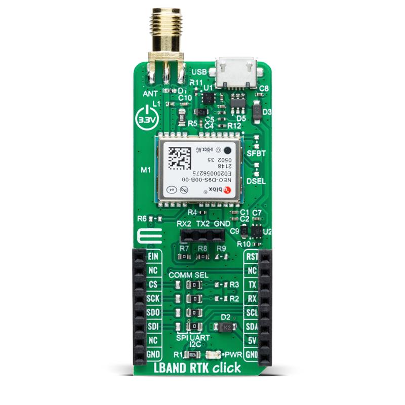
Compact Add-On Board
Provides access to L-band GNSS corrections
LBand RTK Click is a compact add-on featuring the NEO-D9S-00B, a professional-grade, satellite data receiver for L-band corrections from u-blox. Operating in a frequency range from 1,525 MHz to 1,559 MHz, the NEO-D9S-00B decodes the satellite transmission and outputs a correction stream. This enables a high-precision GNSS receiver to reach accuracies down to centimeter-level. An independent stream of correction data, delivered over L-band signals, ensures high availability of position output. LBand RTK Click also uses several mikroBUS pins. In addition, LBand RTK Click contains an SMA antenna for connecting a Mikroe-brand antenna. This antenna easily allows positioning in space, supporting GNSS L-band frequencies. LBand RTK Click implements advanced security features such as signature and anti-jamming mechanisms. It also can be integrated with other GNSS receivers from the u-blox F9 platform.
Mikroe, mikroe.com