Septentrio has launched the AntaRx smart antenna designed for machine automation and control in construction, precision agriculture and logistics.
The smart antenna is enclosed in a rugged and compact housing for simplified installation. It can handle high levels of shocks and vibrations which makes it ideal for harsh industrial environments such as construction and mining.
The multi-frequency receiver offers centimeter-level real-time kinematic (RTK) positioning and can be used in inertial navigation system (INS) integration, dual antenna mode and 4G cellular communication. It is available in several configurations, including as a GNSS smart antenna or a GNSS/INS smart antenna system and can be integrated as an inertial measurement unit (IMU).
AntaRx is the latest addition to Septentrio’s machine control GNSS receiver portfolio. The receiver technology integrates the company’s GNSS+ algorithms, including advanced multipath mitigation, which offers uninterrupted operation in challenging conditions such as near high structures or machinery.
Point One Navigation has been selected by the Indy Autonomous Challenge (IAC) to provide real-time kinematic (RTK) corrections technology to all autonomous racing cars at the Consumer Electronics Show (CES) in Las Vegas.
The Polaris RTK network offers centimeter-accurate location services, which makes autonomous racing at high speeds possible. IAC race cars often exceed 180 mph and require precise location data for safe high-performance racing. The IAC chose Point One Navigation based on the company’s proven record in delivering precise location data to users through its RTK technology.
Point One Navigation’s RTK technology is now available for a wide range of autonomous applications — including UAVs, robots, construction and farm equipment, and autonomous cars and trucks.
The race takes place on Thursday, Jan. 11 at the Las Vegas Motor Speedway. For more information, visit the IAC website.
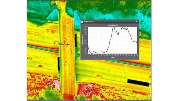
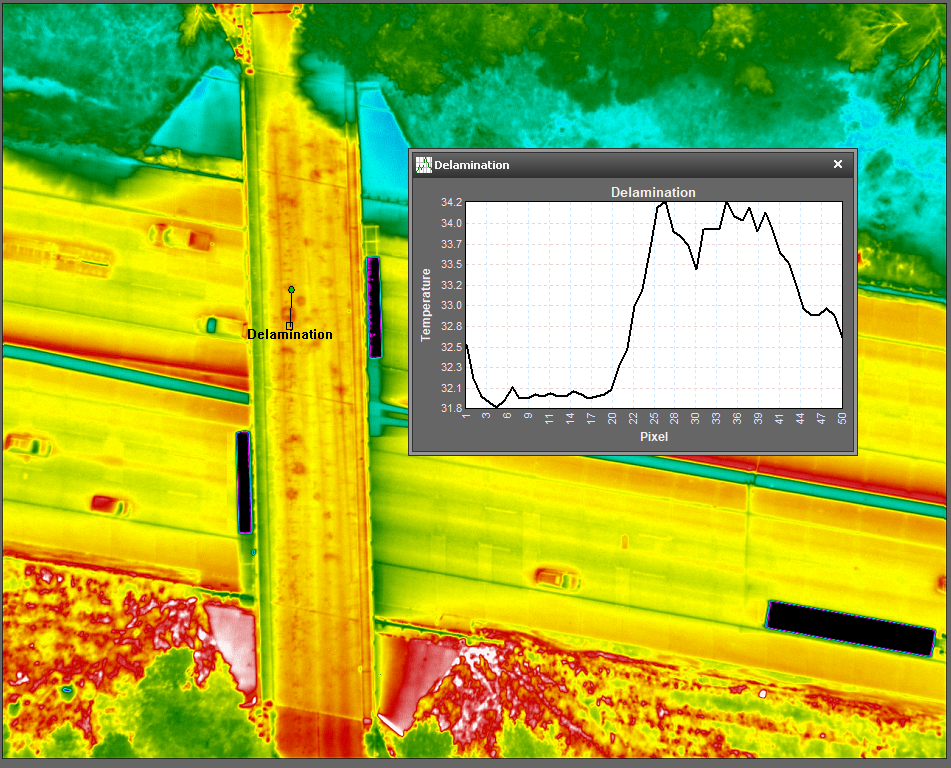
NV5 Geospatial’s thermal infrared (TIR) solutions for transportation infrastructure challenges are now being used in transportation projects to analyze concrete bridges in the Midwest.
This remote sensing technology offering enables local and regional transportation agencies to identify structural problems well before they reach the surface of concrete bridge decks.
Concrete bridge decks require periodic inspections for continuous maintenance, rehabilitation, and replacement work. TIR is used in non-destructive inspection techniques for analyzing concrete bridge decks and identifying potential delamination. This process is made more efficient with aerial collection.
The company recently conducted two separate pilot projects with two Midwestern states’ departments of transportation using aerial data collection to identify thermal anomalies of potential delamination for 200 bridge concrete surfaces. Both projects were completed by flying a fixed-wing aircraft at a low elevation with the thermal sensor mounted to its floor. The flights were conducted without ground-based support.
NV5 Geospatial’s project design focuses on optimal timing and resolution to maximize thermal contrast, which ensures accurate detection of features or patterns of interest. The acquired thermal imagery is orthorectified to create a seamless mosaic for each bridge. TIR imagery can be co-acquired with other airborne technologies, such as true color imagery and lidar, to provide supplementary information.
The TIR aerial solution allows users to capture up to 100 bridges in a single day and offers a detailed and short turnaround of data analysis. It identifies potential issues before ground truthing is required and supports state-wide inspection prioritizations.
ANELLO Photonics has released the ANELLO X3, its 3-axis optical gyroscope inertial measurement unit (IMU) designed for GPS-denied and challenging environments.
The IMU leverages ANELLO SiPhOG (Silicon Photonics Optical Gyroscope) technology and serves as a light, low-power tri-axial optical gyroscope offering high accuracy, performance and reliability for autonomous applications.
The ANELLO X3 can be used in a variety of applications, including autonomous commercial and defense applications involving robots, UAVs, electric vertical take-off and landing (eVTOL) aircraft and various maritime and land vehicle applications, including high-accuracy surveying and mapping.
The Turkish Armed Forces have added the BAHA autonomous sub-cloud UAV to their reconnaissance capabilities. The UAV can be used for tracking, detection, area protection, intelligence and electronic warfare.
The BAHA, developed by Turkish defense company HAVELSAN, is an independent sub-cloud UAV equipped with vertical take-off and landing (VTOL) capabilities. It has complete autonomy in mission execution and allows for the integration of diverse payloads.
With the ability to execute missions at altitudes of up to 15,000 feet, the BAHA has a maximum flight duration of six hours with a gas engine and covers a range of up to 80 kilometers. It also features a 5-kilogram payload capacity and a 3.7-meter wingspan. The system, designed for quick deployment by two individuals and operation by a single person, can be mission-ready within minutes, according to HAVELSAN.
Tested in various regions, challenging climates, and operational conditions, the system has been improved based on feedback from security forces.
HAVELSAN has achieved export success with the BAHA in Africa and Central Asia this year. After successful tests, it is now available for domestic use by security forces.
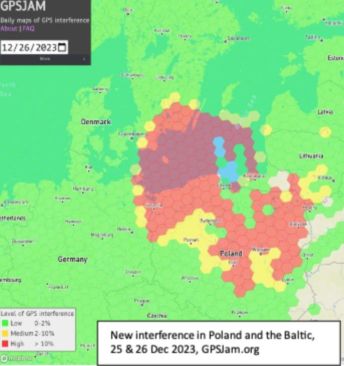
Parts of Poland, Lithuania, southern Sweden, and other countries in the Baltic region had an unexpected Christmas present this year. GPS signals were disrupted and not available in many areas on the 25th and 26th of December. Poland seemed to be particularly impacted, with the northern two-thirds of the country affected and many users on the ground and in the air having to make do without reliable service.
On New Year’s Eve, parts of Finland experienced significant jamming as well. The most visible impacts of the holiday events were seen in aviation and low navigation integrity reports from ADS-B systems. These were displayed on the GPSJam.org website.
Experts in the United States and Poland point to Russia as the source of the interference. They say that Russian anger over the activation of a U.S. anti-missile system in northern Poland in mid-December, and Sweden’s progress toward NATO membership with a recent positive vote in the Turkish Parliament were likely motivations.
Such a reaction by Russia is not unprecedented. In 2022 President Putin threatened Finland and Sweden with invasion if they sought to join NATO. Subsequently, Finnish President Niinistö met with President Biden to discuss improving defense ties. Shortly thereafter planes flying over Kaliningrad and nearby areas in the Baltic began reporting GPS jamming. Analyses of the event by graduate students at the University of Texas Radionavigation Laboratory and Stanford University have provided some details and will likely reveal more as time goes by.
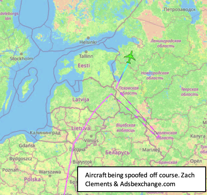
Zach Clements at U.T. studied the disruption and discovered that it included several transmitters spread across a wide area. Some were simply jamming GPS signals to deny service. At least one transmitter was spoofing aircraft so their instruments would show them far from their actual location.
While the phenomenon known as “circle spoofing” has been frequently observed with ships, this was the first time it was reported in aviation. With circle spoofing a receiver is electronically captured and “moved” to a different location. Then it is made to appear to move in circles, almost always in a clockwise direction
Image: Zach Clements/ GPSJam.org
Clements is reasonably sure the source of the circle spoofing was inside Russia. “The points at which the aircraft began to be impacted by the spoofing and where they regained authentic GPS indicate that the spoofer is somewhere in Western Russia. Interestingly, the location to which the aircraft were spoofed is a field about a kilometer from Russia’s decommissioned Smolensk military airbase.”
Zixi Liu at Stanford has discovered that the interference was actually two separate events. The first lasted from 9:30 PM on the 24th until 4:30 AM on the 25th, with the second beginning around 2:30 PM on the 25th and tapering off around midnight on the 26th.
Aviation interests have become increasingly concerned about interference with GPS signals since 2019 when a commercial passenger aircraft flying through smoke nearly impacted a mountain. Since then, aviation groups have raised the issue, national authorities have been regularly issuing warnings, and the UN’s International Civil Aviation Organization has urged its member nations to take action to prevent interference.
“Aviation is always at greater risk when GPS signals are not available or are compromised in some way,” according to Joe Burns, a senior captain at a major international air carrier. Burns is also a member of a board that advises the U.S. government on GPS and related issues. “Interference with GPS increases the risks of accidents and almost always slows the system down, makes flights longer, and more expensive,” he said.
The International Air Transport Association is meeting this month to discuss GPS interference. Most agree, though, that most meaningful short-term solutions will depend upon the cooperation of national governments across the globe.
A series of powerful earthquakes hit western Japan on Jan. 1, killing at least 55 people and damaging thousands of buildings, vehicles and boats, reported CNN. Japanese officials warn that more earthquakes could lie ahead.
Aftershocks continued to shake Ishikawa Prefecture and nearby areas after the initial magnitude 7.6 earthquake struck the area.
According to Japan’s Geospatial Information Authority (GSI), the earthquake may have shifted land in the Noto region near the peninsula, where the ocean floor shifted and generated tsunami waves of about 80cm in height. GSI said preliminary figures indicate that an observation point in Wajima City in Ishikawa Prefecture saw the biggest shift, which moved about 1.3 meters west.
Land appears to have shifted about 20 centimeters to the northwest in the prefectures of Toyama and Niigata. Several centimeters of land shifts were observed in the Kanto-Koshin region and elsewhere.
Scientists have also been watching Japan from space, comparing satellite images taken before and after the earthquake.
On its latest pass, the ALOS-2 spacecraft reported the distance between itself and the ground had shortened as the Earth’s surface had risen up under the force of the tremor.
Fortunately, the uplift may have lessened the impact of the waves when they arrived at the shoreline, said GSI.
GSI plans to continue analyzing the data for other movements.
Quectel’s upcoming webinar, “High-precision GNSS for industrial applications: best practice for design and implementation — North America” will take place Wednesday, Jan. 17, 2024, from 12:00 to 2:00 EST.
High-precision GNSS can be the difference between success and failure for industrial applications – equating as it does to increased efficiency, heightened safety, and superior performance. For example, it enables robotic lawnmowers navigating a lawn with cm-level precision, e-scooters gracefully weaving through bustling urban environments, or handheld devices with pinpoint GNSS location data for informed decision-making. For some industrial applications, including these and many others, high-precision GNSS isn’t just a commercial advantage – it is a necessity.
This webinar offers attendees a unique opportunity to understand high-precision GNSS and how it can revolutionize industrial applications from UAVs to handheld devices. Speakers Victor Pinzo, antenna PDM and Chang Xu, GNSS product manager at Quectel, cover the core components of high-precision GNSS – including GNSS modules, antennas, correction services, and connectivity.
A roundup of recent products in the GNSS and inertial positioning industry from the December 2023 issue of GPS World magazine.
SURVEYING AND MAPPING
Survey Antenna Designed for high-accuracy positioning applications
HX-CSX600A boasts a pre-filtered low noise amplifier (LNA) offering out-of-band rejection, ensuring strong anti-interference performance even in challenging environments. It is designed for high-precision GNSS applications, including agricultural vehicles, small robots and surveying. The antenna offers reliable and consistent satellite signal tracking across a wide range of frequency bands, including GPS, GLONASS, Galileo, BeiDou, QZSS, IRNSS, SBAS, as well as L-band correction services. With advanced multipoint feeding technology, HX-CSX600A maintains a stable phase center variation. Built with an IP67-rated compact and ruggedized housing, this antenna is designed to withstand dust, rain, sunlight, shock and vibration. Its standard TNC-K connector and pole mount aim to simplify the integration process. Harxon, harxon.com
Image: SBG Systems
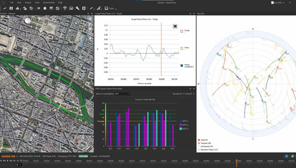
INS/GNSS Post-Processing Software Designed for surveying applications
The Qinertia 4 introduces several features that provide users with a complete solution for precise trajectory and motion analysis. Qinertia is a post-processing software delivering better precision and reliability compared to real-time kinematic systems. It has an enhanced geodesy engine that boasts an extensive selection of preconfigured coordinate reference systems (CRS) and transformations, making it a versatile solution in applications that use diverse geodetic data, including land surveying, hydrography, airborne surveys, construction and more. To tackle the challenges of variable ionospheric activity, the technology uses Ionoshield PPK mode. This feature compensates for ionospheric conditions and baseline distances, allowing users to perform post-processing kinematics (PPK) even for long baselines or harsh ionospheric conditions. Another addition to Qinertia 4 is extended continuously operating reference stations (CORS) network support. This feature offers users a vast network of 5,000 SmartNet stations for reliable GNSS data processing.
Qinertia has more than 10,000 bases in 164 countries. This global coverage ensures Qinertia remains a reliable and efficient solution, regardless of geographic location. In addition, users can import their own base station data and verify its position integrity with precise point positioning (PPP). For data that cannot be processed using PPK, Qinertia 4 offers an alternative solution with its new tightly-coupled PPP algorithm. This new processing mode, available for all users with active Qinertia maintenance, provides post-processing anywhere in the world without a base station, with a horizontal accuracy of 4cm and a vertical accuracy of 8cm. SBG Systems, sbg-systems.com
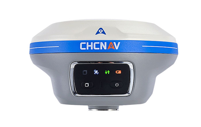
IMU-RTK GNSS Receiver A compact, high-performance receiver with high-end dual camera technology
The i89 visual inertial measurement unit (IMU) GNSS receiver is a surveying device equipped with a 1,408-channel GNSS module that enhances real-time kinematic (RTK) availability, even in challenging environments. Its iStar 2.0 software incorporates advanced ionospheric modeling algorithms, achieving a high integrity RTK fix rate, particularly critical in regions of intense solar activity. The implementation of AUTO-IMU technology eliminates the need for manual initialization, streamlining field operations for increased efficiency. The i89 offers 16.5 hours of battery life and a lightweight 750 g design. The combination of panoramic capture mode and integrated IMU significantly improves the accuracy and efficiency of photogrammetric surveys. CHC Navigation, chcnav.com
GNSS System Features visual positioning capabilities
The Trion V10i GNSS System integrates two cameras for vision-guided surveying operations, an inertial measurement unit (IMU) for tilt surveys and an OLED screen for easy status checks. This device is designed to enhance productivity in the field, even in hard-to-access locations. It features IMU-based tilt compensation for precise measurements of up to 60° with no calibration needed. It also comes with a built-in 4G LTE and UHF and supports NFC, Wi-Fi and Bluetooth. It also offers users seamless connectivity through Trion Survey Cloud for real-time data sharing between field and office teams. FJDynamics, fjdynamics.com
INS For mobile mapping applications
The Atlans 3 is an inertial navigation system (INS) designed for land and air mobile mapping applications. The device is an all-in-one positioning and orientation system integrating unique micro-electro-mechanical systems. MEMS-FOG hybrid technology and a dual-antenna real-time kinematic GNSS receiver are housed within one compact device. The Atlans 3 offers north-keeping capability at FOG-level performance across a variety of land and air mobile mapping applications. It delivers real-time heading, even in GNSS-challenging environments such as urban canyons, mountainous terrain, or forested areas. The lightweight INS is designed to meet the requirements of high-performance lidars mounted on vehicles where space and weight constraints are critical. The Atlans 3 is designed to be quick and simple to install on all platforms. It offers efficient “set-and-forget” operations for a wide range of land and air applications including road and rail asset inventory, pavement condition survey, vehicle automation, HD mapping, ground-truth, airborne surveys and precision pointing. Exail, exail.com
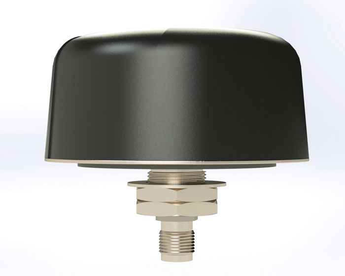
L-Band GNSS Antennas Available in four models
The ARM972XF triple-band plus L-band GNSS antennas provide GPS/QZSS L1/L2/L5, GLONASS-G1/G2/G3, Galileo E1/E5a/E5b, and BeiDou B1/B2a/B2b + L-band coverage. The technology is designed for precision triple-frequency positioning where light weight and a low profile are required. The ARM972XF are small and lightweight housed triple-band precision mini ARINC GNSS antennas. They have an average phase center variation of less than 10 mm for all frequencies and overall azimuths and elevation angles. Additionally, both models are available with components qualified for low-Earth orbit (LEO). Housed in a weatherproof (IP67) enclosure, the ARM972XF is available in four versions. Model ARM972XF-1 (ARM972XF-1-S for LEO space-qualified components) has an integrated 100 mm ground plane, while model ARM972XF-2 (ARM972XF-2-S for LEO space-qualified components) is 83 mm in diameter. The antennas also include Tallysman’s eXtended filtering (XF) technology, designed to mitigate GNSS interference. Tallysman Wireless, tallysman.com
UAV
Helix Antenna Designed for UAVs
The HX-CUX615A has a low-profile design and simple integration process that makes it a suitable antenna for various UAV applications such as aerial photography, remote sensing, infrastructure inspection, traffic control and public security. Equipped with a pre-filtered LNA, HX-CUX615A offers out-of-band interference rejection to mitigate unwanted electromagnetic interference and provide reliable GNSS signals for seamless integration into positioning solutions. This lightweight antenna also adopts patented dual-quadrifilar helix antenna technology, ensuring stable wide-angle circular polarization performance. This results in low-elevation satellite tracking, while maintaining high gain and reliable signal tracking — even in challenging environments. Harxon, harxon.com
VToL UAV A fully autonomous fixed-wing VTOL UAV with multiple power configurations and a heavier payload
The E455 is a fixed wing, vertical takeoff and landing (VTOL) UAV. At 55lbs, the E455 offers a 2-hour flight endurance operating on battery power alone. It is designed to carry a variety of payloads, including mapping sensors, lidar and EO/IR surveillance sensors. Where allowed, the E455 can fly at gross weights up to 65 lbs, which offers users more versatility in payload selection. The E455 also features an open control payload bay, which allows for the seamless integration of custom payloads.
EVENT 38, event38.com
UAV Surveying Software With added UAV photogrammetry capabilities
The Terrain Creator app photogrammetrically processes UAV images to generate survey-grade terrains that then transfer into the traditional Virtual Surveyor workspace. Terrain Creator aims to simplify the aerial photogrammetry process by offering a visual and intuitive application to produce an orthomosaic and a digital surface model (DSM) from UAV photos, the company said. The software was originally developed to bridge the gap between UAV photogrammetric processing applications and engineering design packages. Prior to this new release, users had to rely on third-party software to generate elevation models and an orthomosaic on which they could work with the Virtual Surveyor toolset. Now, users can derive the 3D topographic information necessary for construction, surface mining and excavation projects in one package. Once the survey-grade terrains flow from the Terrain Creator into the Virtual Surveyor desktop app, users can access an interactive virtual environment and robust toolsets to generate CAD models, create cut-and-fill maps and calculations, or calculate volume reports. Users currently subscribed to Virtual Surveyor Ridge and Peak editions will see their software updated automatically with Terrain Creator. A flexible licensing setup will allow two users within a subscribing organization to use the Terrain Creator and Virtual Surveyor applications simultaneously from different computers. Virtual Surveyor, virtual-surveyor.com
MOBILE
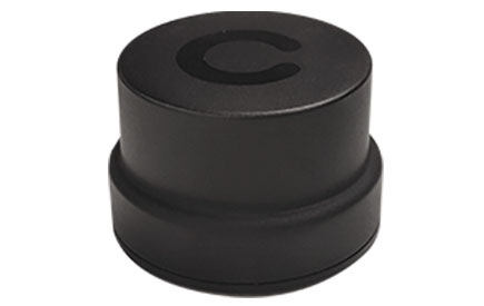
Antenna Designed for high-precision and autonomous multi-frequency applications
The M10HCT-TNC GNSS L1/L2/L5 antenna is ground-plane independent and offers extremely low power consumption and minimal phase-center variation over azimuth crafted for GNSS high-precision applications. The antenna offers suitable axial ratio, ensuring multipath error is mitigated. Several filtering groups allow this antenna to have superb filtering capabilities and RF antijamming mitigation capabilities.
Maxtena, maxtena.com
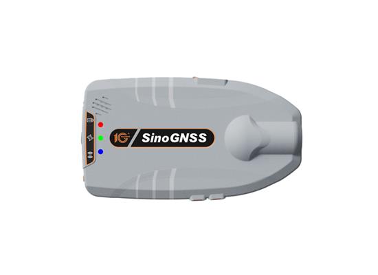
GNSS Receiver Suitable for personnel positioning, IoT, railway patrols, vehicle tracking, and search and rescue missions
Equipped with the SinoGNSS K8 platform, the Z30 can track full constellations and multiple frequencies, providing centimeter-level accuracy. With 965 channels, it is capable of tracking more than 60 GPS, BeiDou, GLONASS, Galileo, QZSS, IRNSS and SBAS satellites. The Z30 features an integrated antenna for stable signal reception. The device is also equipped with two side buttons for power, one-click SOS alerts and three Indicator LEDs for power, satellite, and differential status checks. It supports NTRIP and TCP protocols, enabling various personnel positioning applications by uploading position data. The Z30 integrates with NaviCloud, offering functions such as real time location display, historical trajectory query, remote control, and electric fence. In addition, it can be customized to meet specific customer requirements. With indoor and outdoor positioning capabilities, the Z30 is a suitable solution for various fields. It supports outdoor real-time kinematic positioning with centimeter-level accuracy and indoor Bluetooth positioning with sub-meter-level accuracy. ComNav Technology, comnavtech.com
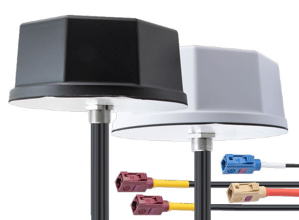
Antennas IoT multiband antennas designed for multiple mobile applications
The Pasternack IoT multiband combination antennas are designed for vehicles, fleets and pivotal base stations. The technology aims to revolutionize how industries perceive and use mobile connectivity. The antennas integrate 4G, 5G, Wi-Fi and GPS bands to offer emergency teams, on-the-move fleets and first responders an unwavering link, even in harsh environments. Facilitated with both FAKRA and SMA connectors and extended 17-foot cable leads, users can seamlessly integrate the technology. It also has an IP69K rating, certifying it for both indoor and outdoor deployments. MIMO capabilities improve data transmission speeds and reliability, ensuring consistent high-bandwidth connections. The antenna’s GPS/GNSS component, enhanced with LNA and amplified by a 26 dB gain, offers users improved navigation and tracking precision. Pasternack, pasternack.com
The European Union Agency for the Space Program (EUSPA), in collaboration with the European Commission, has published a new version of the Galileo Open Service Signal in Space Interface Control Document (OS SIS ICD).
The latest version, denoted v2.1, introduces new elements supporting the improvement and enlargement of the Galileo service portfolio. OS SIS ICD v2.1 is available along with a corresponding new version of the OS Service Definition Document (OS SDD).
New elements in v2.1 include the definition of OS Extended Operation Mode (EOM) and criteria for identifying when it is activated; description of a new ARAIM Integrity Support Message (ISM), and a new annex detailing a numerical example for the computation of its 32-bit checksum; and a new annex detailing the Galileo PRN Codes Assignment process, including codes belonging to the families E1 B, E1 C, E6 B, E6 C, E5a I, E5a Q, E5b I, E5b Q are now available.
The annex dealing with the authorization of Galileo trademarks, now obsolete, has been removed.
The Galileo OS SIS ICD provides the information required by receiver and chipset manufacturers, application developers and service providers to process the open service signals generated by Galileo satellites. It specifies Galileo signal characteristics; characteristics of Galileo spreading codes; Galileo message structure and data contents; and OS Signal in Space flags.
OS SIS ICD v2.1 pertains to receiver technology developers. The availability of adapted receivers is a key requirement for translating the full range of Galileo signals into useful services, according to EUSPA. The agency added it has been engaged in regular dialogue with advanced chipset and receiver manufacturers, working to see Galileo fully integrated into the latest generation of receivers.
The previous OS SIS ICD, version 2.0, was published by the European Commission in January 2021. In the modification of the ICD, the principle of backward compatibility for Galileo receivers has, as always, been applied.
Inertial Labs and BayesMap have partnered to release PCMasterPro software updates for Inertial Labs’ Resepi.
The collaboration aims to provide users with fast, automated point cloud alignment to enhance UAV lidar systems. The software is designed to simplify the process of geometric calibration and quality control.
Resepi is a sensor-fusion platform designed for accuracy-focused remote sensing applications. It utilizes a high-performance Inertial Labs INS and a high-accuracy dual antenna GNSS receiver, integrated with a Linux-based processing core and data-logging software. The platform also provides a WiFi interface, optional imaging module, and external cellular modem for RTCM corrections. Resepi can be operated by a single hardware button or from a wirelessly connected device via a simple web interface.
The software update is now available to all Resepi users.
The National Geodetic Survey (NGS) has announced that users have until February 29, 2024, to submit data for the initial National Spatial Reference System (NSRS) modernization rollout. This means time is running out to submit GNSS or leveling data for initial NSRS Modernization. It is anticipated that NGS will release the new, modernized NSRS in 2025, once new data is incorporated into the database. The following newsletter will provide some advice on strategically selecting marks to improve the local accuracy of the NAVD 88-to-NAPGD 2022 transformation tool.
Image: NGS website
As the announcement stated, NGS is in the process of compiling, organizing, and cleaning all the relevant GNSS and leveling data contained within the NGS Integrated Database and the OPUS shared solutions database for preparation of the new, modernized NSRS. The data will be used in national scale survey adjustments using NGS’ new software package called LASER (Least-squares Adjustments: Statistics, Estimates, and Residuals). The adjustments will compute the initial sets of geometric and orthometric reference epoch coordinates (RECs) on many existing survey control marks and CORS around the country. The definitions of RECs and survey epoch coordinates (SECs) are spelled out in NOAA Technical Report NOS NGS 67, NGS’s Blueprint Part 3. My April 2021GPS World newsletter highlighted the Blueprint Part 3 document, and my August 2022GPS World newsletter provided details on RECs and SECs. Using the results of the adjustments, NGS will produce a suite of models and tools that will enable users to access and work within the Modernized NSRS.
During the last several years, NGS’ GPS on Benchmarks program has been encouraging stakeholders and partners around the country to submit GNSS data to NGS on marks that they use. This will ensure that these marks will have updated RECs when the new system is implemented. Also, just as important, marks that also have North American Vertical Datum of 1988 (NAVD 88) heights will be used to improve the local accuracy of the NAVD 88-to-NAPGD 2022 transformation tool.
NGS’ plans include accepting user data, but after February 29, 2024, they will not include additional GNSS and leveling data for the initial REC national adjustment and for use in building the transformation tools. In 2018, I wrote a series of GPS World newsletters that highlighted NGS’ GPS on BM program (February 2018, April 2018, June 2018, and August 2018). At that time, the GPS on BM program was very useful in the development and implementation of the hybrid geoid model GEOID18. This newsletter will provide an update on the GPS on BM Transformation Program and provide some advice on strategically selecting marks to improve the local accuracy of the NAVD 88-to-NAPGD 2022 transformation tool.
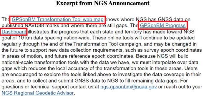
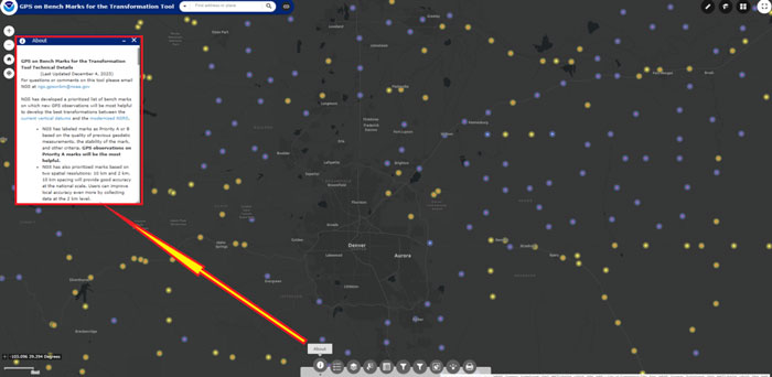
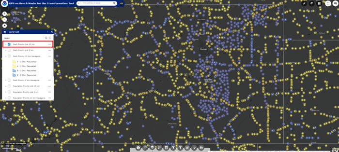
When users click the link GPSonBM Transformation Tool Web Map, they are connected to a web map depicting a prioritized list of marks where new GNSS observations would be most helpful to the development of the transformation model between the current vertical datum (e.g., NAVD 88) and the modernized NSRS.
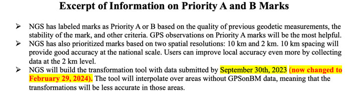
NGS’ prioritized list of benchmarks are labeled as Priority A or B. Clicking on the “About” button on the webpage provides information about the priority marks. See the boxes titled “GPSonBM Transformation Tool Web Map” and “Excerpt of Information on Priority A and B Marks.”
GPS on BM Transformation Tool Web Map. (Image: NGS website)
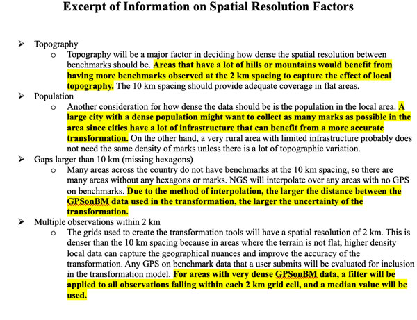
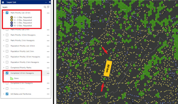
To assist users in their selection of marks, NGS developed criteria based on spatial resolution factors. See the box titled “Excerpt of Information on Spatial Resolution Factors.” As previously stated, time is running out. In my opinion, users should prioritize their GPS on BM plans based on the NGS’ criteria. I have highlighted what is important for users to consider when selecting marks.
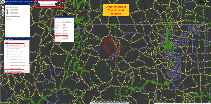
Many areas across the country do not have benchmarks at the 10 km spacing, so there are some areas without any hexagons or marks. As stated in the spatial resolution factors, NGS will interpolate over any areas with no GPS on benchmarks. In areas that have gaps larger than 10 km, that is, that are missing hexagons, I would recommend occupying several marks in each hexagon surrounding the gap to ensure that marks with valid NAVD 88 heights are part of the transformation tool. The web tool defaults to the Denver, Colorado, region when you access it but users can drag the map to an area of their interest or select a location.
Locating marks using the GPSonBM transformation tool web map. (Image: NGS Website)
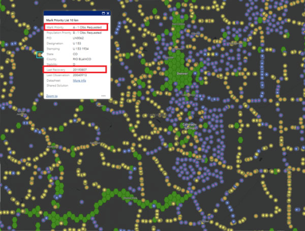
Acquiring data in mountainous regions and areas that have large distances between completed hexagons is probably the most important for users to focus on. The box titled “Locating Marks Using the GPS on BM Transformation Tool Web Map” provide marks that need to be observed. As an example, I have highlighted two areas that have large distances between benchmarks and completed hexagons. In this case, it would be important to occupy a couple of marks in the highlighted locations. Clicking on a mark provides a box with the following information: Mark Priority, Population Priority, PID, Designation, Stamping, State, County, Stability code, Last Date of Recovery, Last Date of Observation, Link to NGS Datasheet, and a Link to a Shared Solution (if one exists).
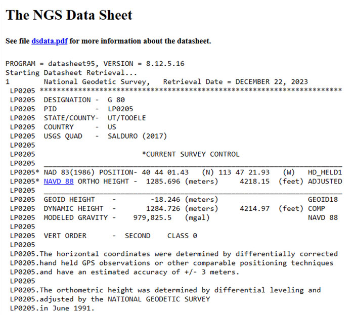
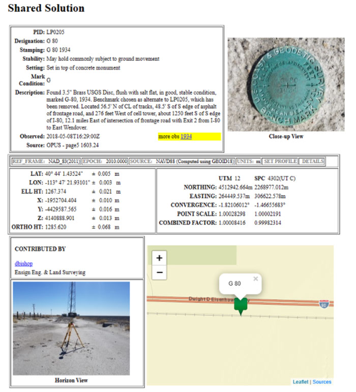
Clicking the link titled “More Info” next to Datasheet brings up the NGS datasheet for the mark, and clicking the link titled “More Info” next to Shared Solution” brings up the Shared Solution information (see the boxes titled “Mark Priority Information for Mark G 80,” “Excerpt from NGS Datasheet for Mark G 80,” and “Shared Solution for Mark G 80.”). I would recommend that State surveying organizations (and surveyors) perform this type of analysis and strategically occupy marks that fill in important gaps. There is less than two months remaining to submit data to NGS that will support the transformation tool.
Excerpt from NGS datasheet for Mark G 80. (Image: NGS website)Shared solution for Mark G 80. (Image: NGS website)
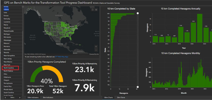
The GPSonBM Progress Dashboard illustrates the progress that each state and territory has made toward NGS’ goal of 10 km (and 2 km) data spacing nationwide.
GPSonBM Program Dashboard. (Image: NGS website)
Users can see the GPS on Benchmark information for a particular state by clicking on the name of the state on the left side of the website.
Selection of North Carolina. (Image: NGS website)
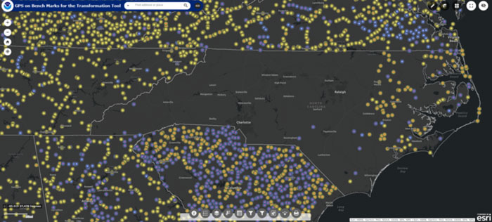
I highlighted North Carolina because I live in that state. The map informs the users of how many 10 km priority A (89) and B (32) marks are remaining to be occupied, and the percentage completed (92%). Clicking on the link “To see remaining marks to be collected use GTT Web Map App,” located under the map, depicts the remaining marks to be collected. As you can see from the plot, North Carolina has several marks in the eastern portion of the state that still need to be occupied with GNSS.
Status of GPS on benchmarks in North Carolina. (Image: NGS website)
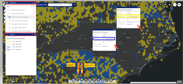
A nice feature of the map is the legend and layer list buttons. Also, information about the mark appears if you click on a mark.
Example of legend and layer list. (Image: NGS website)
The image below provides a list of layers that can be selected using the webtool.
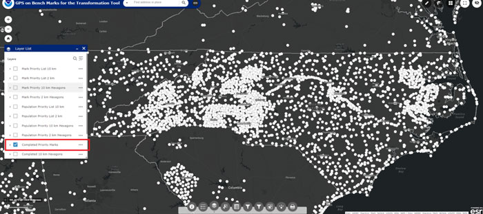
The following image depicts marks that have been completed. As you see from the plot, North Carolina has been very active in the GPS on Benchmark program.
Completed marks in North Carolina. (Image: NGS website)
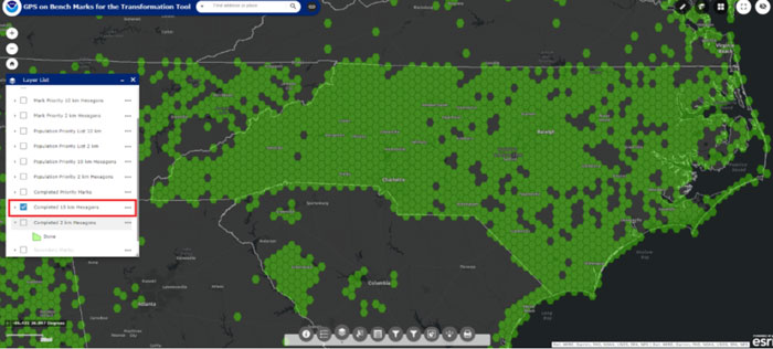
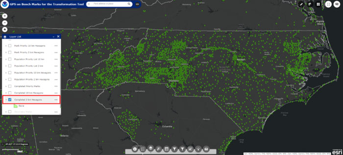
Users can also click on the button to see which 10 km (and 2 km) hexagons have been completed (see the boxes titled “Completed 10 km Hexagons in North Carolina” and “Completed 2 km Hexagons in North Carolina”).
Completed 10km Hexagons in North Carolina. (Image: NGS website)Completed 2km Hexagons in North Carolina. (mage: NGS website)
The North Carolina Geodetic Survey, under the leadership of Gary Thomson, along with NC surveyors has been involved with the GPSonBM program from its inception.
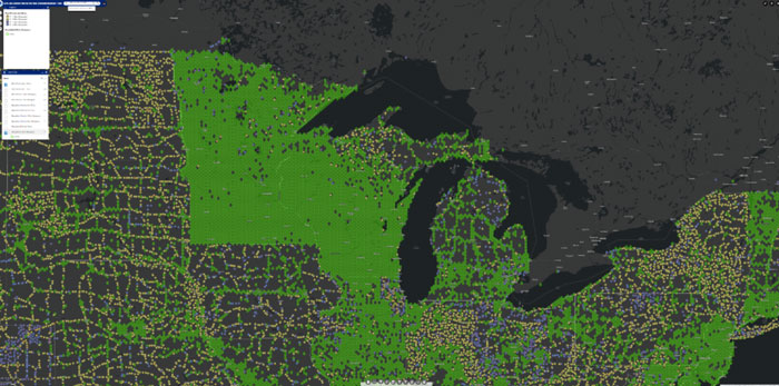
As previously stated, the website provides the list of priority benchmarks and the status of GPS on Benchmark for each state. There are other states that have been very active in the GPS on Benchmark program such as Minnesota and Wisconsin.
Completed 10 km Hexagons in Great Lakes Region. (Image: NGS website)
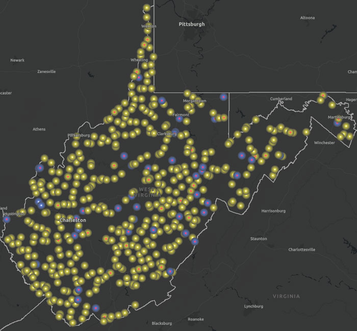
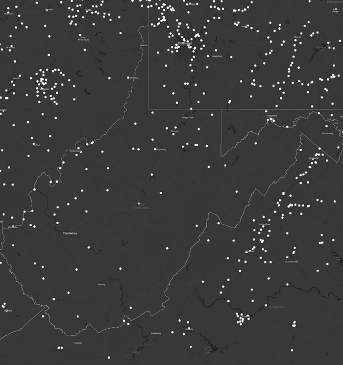
The following images provide the GPS on Benchmark information for West Virginia.
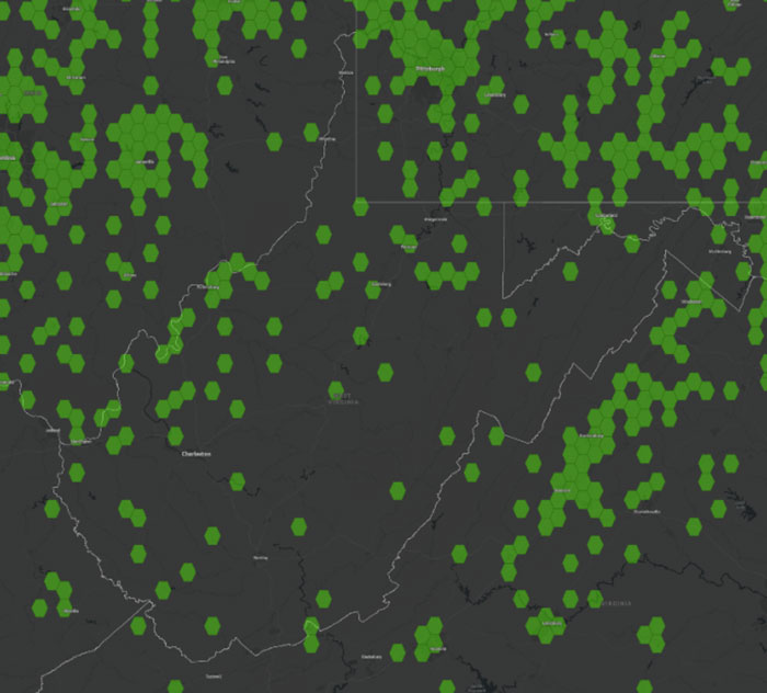
Status of GPS on benchmarks in West Virginia. (Image: NGS website)Completed marks in West Virginia. (NGS website)Completed 10 km hexagons in West Virginia. (Image: NGS)
The following image provides a plot of an area in West Virigina that highlights a region with a large gap between completed 10 km hexagons. If a user was interested in supporting the development of the transformation model in West Virigina, occupying a mark with GNSS in this area would help improve the local accuracy of the NAVD 88-to-NAPGD 2022 transformation tool.
Overlay of completed and status of benchmarks in West Virginia. (Image: NGS website)
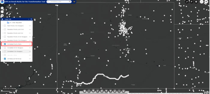
North Carolina and West Virginia are not large states compared to some western states. The boxes titled “Status of GPS on Benchmarks in Colorado,” “Completed Marks in Colorado,” “Completed 10 km Hexagons in Colorado,” and “Overlay of Completed and Status of Benchmarks in Colorado” provide the information for Colorado. Looking at the plots there appears to be many regions that could use GPS on Benchmark occupations.
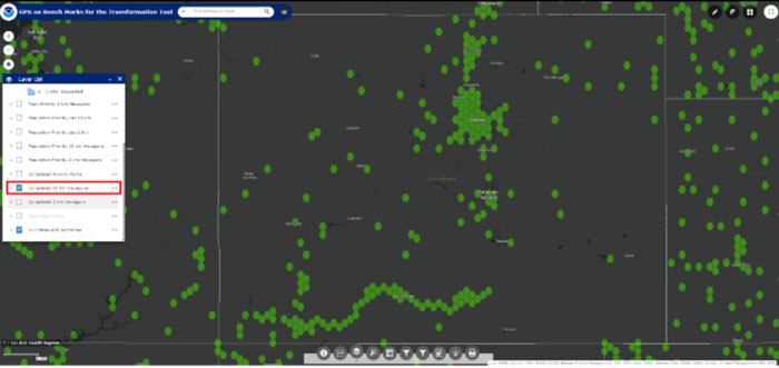
Status of GPS on benchmarks in Colorado. (Image: NGS website)Completed marks in Colorado. (Image: NGS)Completed 10 km hexagons in Colorado. (Image: NGS website)
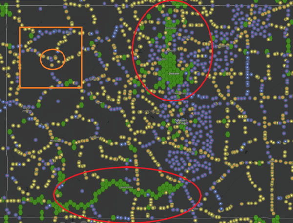
Looking at the plot in the image below, there appear to be many marks that were occupied in populated areas such as Denver, Fort Collins, and Colorado Springs. The marks along the southern border were part of NGS’ 2017 Geoid Slope Validation Survey (GSVS) Project. The area highlighted by the orange box is an area that is lacking GPS on Benchmark occupations. The distance between the nearest completed 10 km hexagon is 60 kilometers. In other words, the two completed hexagons are more than 120 km apart. As previously stated, NGS will interpolate over any areas with no GPS on benchmarks.
Overlay of completed and status of benchmarks in Colorado. (Image: NGS website)
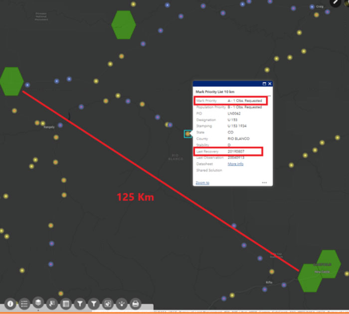
Again, in areas that have gaps larger than 10 km with missing hexagons, I recommend occupying several marks in each hexagon surrounding the gap to ensure that marks with valid NAVD 88 heights are part of the transformation tool. To demonstrate this concept, I have selected an area in Colorado near benchmark U 153 (PID LN0062).
Benchmark U 153 in Colorado. (Image: NGS website)
The following image depicts the locations of the completed hexagons near benchmark U 153.
NGS has developed web tools to assist users in the selection of marks for the program. Two web tools that I find useful are the Leveling Project Page and the Passive Mark Page. The Leveling Project Page provides information on leveling line data. Users can find information about the marks involved with a certain leveling line. There are links to the Passive Mark Page and NGS datasheets on the Leveling Project Page. My October 2020GPS World newsletter described the Passive Mark Page web tool in more detail, and my June 2021GPS World newsletter demonstrated the use of the tools.
In this example, I selected U 153 because it was located between two completed 10 km hexagons that are 125 km apart. That said, looking at the information from the passive mark web tool, it appears that the published height of the benchmark is based on 1934 leveling data. That by itself is not a bad thing but the Orthometric Height Residual is very large (-23.1 cm). This implies that the difference between the GNSS-derived orthometric height using Geoid18 and the published NAVD 88 height disagreed by 23.1cm. This could be due to the movement of the mark and, in my opinion, is not a good candidate for the transformation tool.
As previously stated, NGS’ Leveling Project Page, provides information on the benchmarks and associated data involved in a leveling line. See the box titled “Excerpt from NGS Leveling Project Page for L2577.” Users can find information about all the marks involved with a certain leveling line.
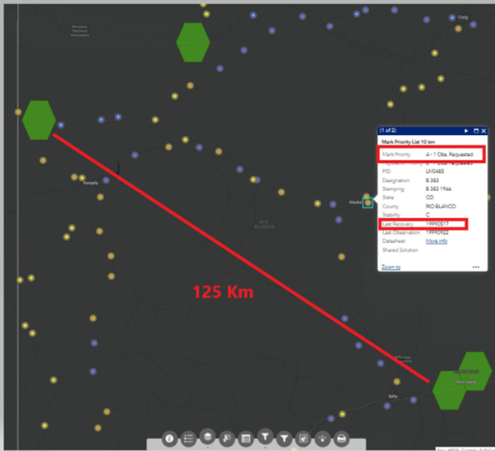
Excerpt from NGS Leveling Project page for L2577. (Image: NGS website)Distance between 10km hexagons near B 383 in Colorado. (Image: NGS website)
Again, I used the Passive Mark tool to find detailed information about the mark. See the box titled “Excerpt from NGS Passive Mark Tool for B 383.” This mark was last leveled in 1966 and the Orthometric Height Residual is small (1.2 cm). This implies that the difference between the GNSS-derived orthometric height using Geoid18 and the published NAVD 88 height disagreed by 1.2 cm.
This could be a good candidate for the GPS on BM program and the transformation tool.
Excerpt from NGS passive mark tool for B 383. (Image: NGS)
For completeness, I looked at another mark in the same area.
Distance Between 10km hexagons near B 154 in Colorado. (Image: NGS website)
I highlighted this mark because it was last leveled on the same 1934 leveling line as mark U 153. Unlike U 153, looking at the information provided by the Passive Mark tool for B 154 indicates that the GNSS-derived orthometric height agrees with the published leveling-derived orthometric height. The orthometric height residual is only -2.1 cm. This would be another good candidate to fill the area between the two completed hexagons.
This newsletter provided some advice on strategically selecting marks to improve the local accuracy of the NAVD 88-to-NAPGD 2022 transformation tool. Again, I would recommend that state surveying organizations and surveyors perform the analysis described above and strategically occupy marks that fill in important gaps. There is less than two months remaining to submit data to NGS that will support the transformation tool.
NGS has developed web tools such as Passive Mark Page and Leveling Project Page to assist users in identifying marks for inclusion in the development of the transformation model between the current vertical datums (e.g., NAVD 88) and the modernized NSRS.