A roundup of recent products in the GNSS and inertial positioning industry from the August 2023 issue of GPS World magazine.
SURVEYING & MAPPING
 Laser Scanner
With several integration options
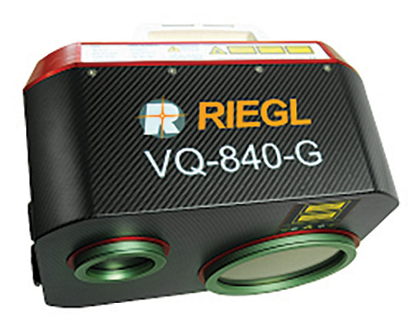
The VQ-840-G is a fully integrated compact airborne laser scanner designed for combined topographic and bathymetric airborne and UAV-based surveying. The system is offered with an optionally integrated and factory-calibrated inertial measurement unit/GNSS system and can be complemented with an optional camera or IR rangefinder. It also has an optional integrated inertial navigation system. The scanner carries out laser range measurements for high resolution surveying of underwater topography with a narrow, visible green laser beam, emitted from a pulsed laser source. The VQ-840-G has high spatial resolution due to a measurement rate of 200 kHz and high scanning speed of up to 100 scans/second.
Riegl, riegl.com

Laser Scanning System
A versatile reality capture solution suitable for surveying, construction and engineering users
The X9 is designed to enhance performance in more environments while leveraging Trimble’s X-Drive technology for automatic instrument calibration, survey-grade self-leveling and laser pointer for georeferencing. The X9 expands on Trimble’s X7, delivering longer range, higher accuracy, shorter scan times and sensitivity, improving scan results. Advanced processing and a high-performance laser increase the sensitivity of all scans, enabling the X9 to capture difficult dark or reflective surfaces. A new center unit design also improves signal transmission for better scan quality. The X9 provides accurate and dependable data, enabling confident decision making both in the field and in the office through in-field registration with Trimble Perspective and FieldLink software by minimizing the need for target deployment. The auto-calibration eliminates the need for annual calibration. In addition, the X9 includes survey-grade self-leveling with the industry’s widest compensation range for fast, easy setup. The X9 data can be delivered directly from the Perspective or FieldLink software to Trimble’s office software — including the Realworks 3D scanning software — business center office software, SketchUp and Tekla, or exported to industry-standard formats to produce application-specific deliverables.
Trimble, trimble.com
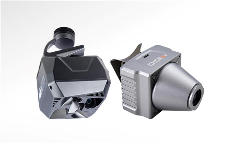
Survey Cameras
For photogrammetric applications and to complement lidar survey data
The C5 and C30 orthographic and oblique cameras are designed for aerial surveys. The systems provide high-quality imaging solutions for photogrammetric applications and to complement lidar survey data. The C5 camera is an efficient and lightweight system for aerial surveys, weighing 290 g for increased flight endurance. Its compact size of 75 mm x 63.5 mm x 102.5 mm allows easy integration into UAVs. The C30 camera’s weight is 600 g with a size of 110mm x 108 mm x 85 mm. The C30 is also designed for aerial surveying. The C5 and C30 cameras’ universal installation design makes them compatible with a wide range of fixed-wing and rotor UAV platforms. Both cameras are supported by the CHCNAV’s BB4 Mini and P330 Pro UAVs as well as the DJI’s M300 RTK. The C5 and C30 cameras give maximum flexibility for photogrammetric applications. They can be used independently on real-time kinematic-enabled UAVs to capture high-resolution imagery or installed directly on the CHCNAV’s lidar series to colorize point cloud data. This feature allows seamless imagery and lidar data integration for a more complete view of the surveyed area.
CHC Navigation, chcnav.com
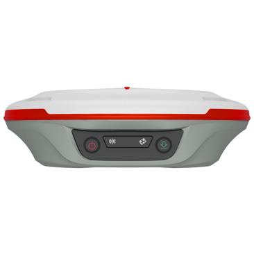
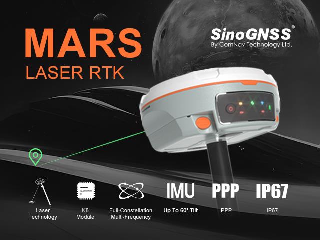
GNSS Palm RTK
For surveying and mapping, GIS and more
The T20 is light, weighing 0.68 kg, and has low power consumption with 12 hours of battery life. It integrates functions such as a GNSS module, datalink module, 4G, 5.0 dual-mode Bluetooth, data memory system and more. Powered by the SinoGNSS K8 high precision module, the T20 has 1,590 channels and can track all running and planned constellations including GPS, BDS, GLONASS, Galileo, QZSS and satellite-based augmentation systems. Additionally, the anti-interference algorithm enables the T20 to maintain accurate positioning and perform well in complex environments, providing surveyors with high-quality measurements. The T20 is equipped with a third-generation inertial measurement unit from ComNav, which can be tilted and measured at an angle up to 60°. The T20 is also equipped with a U50 datalink module, which enables it to switch between base and rover. The T20 is compatible with mainstream real-time kinematic receivers on the market.
ComNav Technology, comnavtech.com
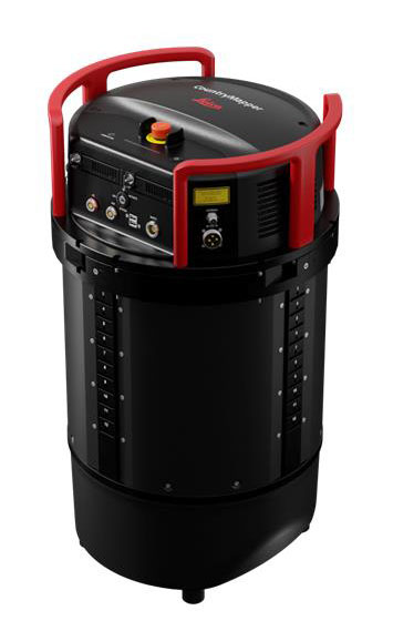
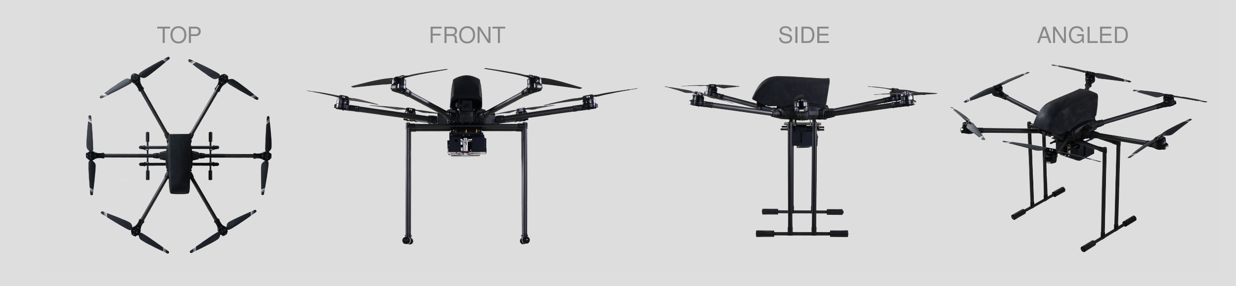
Hybrid Imaging and Lidar Sensor
Designed for airborne mapping
The CountryMapper is designed for large-area imaging and lidar mapping. Combining a large-format photogrammetric camera with a high-performance lidar unit into a single system, the CountryMapper collects foundational geospatial data simultaneously to support a wide variety of user applications. The CountryMapper combines imaging and lidar sensor modules into a highly efficient hybrid airborne system. The sensor features CMOS-based Leica MFC150 camera modules that leverage true mechanical forward-motion-compensation to deliver high image quality. The sensor’s new Hyperion3 lidar unit features 60° field of view, improving the performance and flexibility of the system compared to previous lidar modules, while reduced laser divergence provides greater planimetric accuracy and better foliage penetration. The CountryMapper fully integrates with Leica HxMap multi-sensor end-to-end processing workflow, enabling distributed processing of images and point clouds to optimize productivity for very large data sets. The CountryMapper supports applications such as orthophoto generation, terrain mapping, hydrography, forestry monitoring and infrastructure management. Users of previous-generation sensors can leverage their initial investment and upgrade their systems to the CountryMapper configuration.
Leica Geosystems, leica-geosystems.com
MOBILE
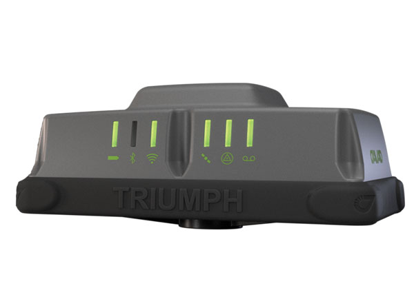
GNSS Network Rover
Complete with an integrated MEMS IMU
The Triumph-3NR (T3-NR) is a small, lightweight GNSS network rover with more than 25 hours of run time on a single charge. The T3-NR easily connects to real-time networks for corrections to get GNSS real-time kinematic with inertial measurement unit tilt compensation. The network rover has 874 channels and can track all constellations. It features an internal GNSS antenna, Wi-Fi, Bluetooth, and is USB compatible. The T3-NR is suitable for demanding industrial applications.
JAVAD, javad.com
Antennas
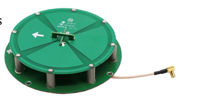
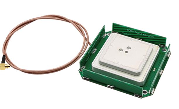
Suitable for lawn mowers and other mobile applications
The HX-CSX014A is a high gain, low profile and compact antenna with a new structure that simplifies integration into lawn mowers and minimizes the overall machine dimension. It features small size, high sensitivity and low power consumption. The HX-CSX231A, is a ready-to-use GNSS antenna with a highly reliable structure that makes it small and lightweight. It exhibits 4.5 dBi high gain performance with ultra-low signal loss. It also delivers wide beam width that covers wide frequencies with high marginal gain, a perfect option in complex environments. Additionally, the HX-CSX231A’s advanced LNA features improved signal filtering, out-of-band rejection, restrained unwanted electromagnetic interferences and a strong multi-path reduction capacity.
Harxon, en.harxon.com
DEFENSE
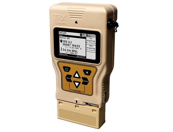
PNT Device
Enables dismounted maneuver operations even where GPS is compromised or denied
The TRX DAPS II provides assured positioning, navigation, and timing (PNT) to dismounted users by disseminating assured position and time to dependent devices in GPS-challenged environments. TRX DAPS II fuses inputs from M-code GPS, inertial sensors, and complementary PNT sources. It is a small, lightweight PNT device that supports both standalone operation and integration with the Nett Warrior ensemble. It also can distribute PNT information to a customized tactical watch. The TRX DAPS II solution employs a modular architecture and adheres to Army PNT interface standards, facilitating the addition of new PNT sensors as threats evolve. This device will be in production for the Army later this year.
TRX Systems, trxsystems.com
TIMING
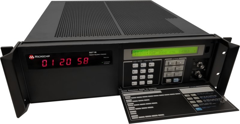
Atomic Clock
Maintains system synchronization when GNSS signals are denied
The 5071B cesium atomic clock can perform autonomous time keeping for months in the event of GNSS denials. This device is the next-generation commercial cesium clock to the 5071A. The 5071B is available in a three-unit height, 19-in rackmount enclosure, providing a compact product to work in environments where it can be easily transported and secured versus a larger alternative designed specifically for laboratory environments. The 5071B has upgraded electronic components to address possible obsolescence or non-RoHS circuitry. The clock provides 100 ns holdover for more than two months, maintaining system synchronization when GNSS signals, such as GPS, are denied. As a cesium beam tube product with no deterministic long-term frequency drift, the 5071B provides absolute frequency accuracy of 5E-13 or 500 quadrillionths over all specified environmental conditions for the life of the product. For military applications requiring rapid deployments for system radars, 5E-13 stability eliminates the need for the acquisition of external synchronization sources prior to radiating.
Microchip Technology, microchip.com
OEM
GNSS Positioning Modules
For multiple applications
automation of moving industrial machinery, and the ZED-F9P-15B provides customers in the mobile robotics market with an L1/L5 option in addition to the L1/L2 bands. These two modules are based on the u-blox F9 high-precision GNSS platform. The NEO-F9P and the ZED-F9P-15B GNSS modules feature concurrent reception of GPS, Galileo, and BeiDou; multi-band L1/L5 real-time kinematic; short convergence times; and reliable performance. The modules deliver centimeter-level accuracy in seconds and come in small, high-precision form factors.
Its small size, coupled with very low power consumption and ANN-MB1 antenna compatibility, makes the NEO-F9P suitable for a wide range of uses. Offering reliable and efficient positioning, the module supports open as well as standards-based correction services for enhanced performance, such as the u-blox PointPerfect GNSS augmentation service.
u-blox, u-blox.com
GNSS Receiver Module
Features built-in AIM+ technology for interference mitigation
The mosaic-X5 is a multi-band, multi-constellation GNSS receiver in a low power surface mount module with a wide array of interfaces. It is designed for mass market applications such as robotics and autonomous systems — capable of tracking all GNSS constellations, supporting current and future signals. The mosaic-X5 has an update rate of 100 Hz, is easy to integrate, and is optimized for automated assembly. The mosaic-x5 is suitable for autonomous vehicles, logistics and port operations, mining and construction, precision agriculture, rail, robotics, surveying and mapping, UAVs and more.
Septentrio, spetentrio.com