Anyone keeping up with my columns may know that I have been highlighting the geodesy crisis and programs that advance the science of geodesy (July 2020, November 2022, December 2022, and March 2023). On June 13-15, I had the privilege of participating in a working group event convened by the Geomatics Emerging Scientist Consortium for Education, Research and Capabilities Enhancement (GEO-ESCON). The GEO-ESCON, established in the summer of 2022, is a multi-university consortium serving the need of the Office of Geomatics of the National Geospatial-Intelligence Agency (NGA) for personnel with advanced geomatics expertise, a sustainable pipeline of critical geomatics skillsets, and capabilities enhancement in geomatics and other applied sciences. The 15-member consortium is led by The Ohio State University (OSU), which serves as GEO-ESCON’s managing higher education partner.
GEO-ESCON is part of OSU’s Battelle Center for Science, Engineering and Public Policy in the John Glenn College of Public Affairs. As stated in an OSU press release, OSU was selected for its role with GEO-ESCON because of its longstanding commitment to geodetic education — its collegiate geodetic program is the oldest in the United States and offers undergraduate and graduate degrees in both geodetic engineering and geodetic science.
OSU is home to more than 80 researchers across six colleges who focus on core research and development aspects of geospatial science and technology, including geodesy, remote sensing, photogrammetry, GIS, positioning, navigation, and timing (PNT), computer vision, mobility, smart cities, data analytics, autonomous systems (UAS, UUS and UGV), medical imaging, and precision agriculture.
The GEO-ESCON consortium is designed to create a geographically distributed, multi-disciplinary network of universities to educate the federal geomatics workforce at advanced levels and provide opportunities for applied research and technology development. Higher education institutions are invited to participate in GEO-ESCON based on their capabilities in geomatics. As of July 18, the consortium has 15 members and two additional universities are in the process of becoming members. Click here for all GEO-ESCON member institutions.
GEO-ESCON convened the June Geomatics Challenge Working Group to discuss pressing geomatics challenges and discuss potential solutions. The event facilitated dialogue between representatives from NGA’s Office of Geomatics and academic attendees on geomatics challenges of national priority that could result in actionable proposals to address the challenges. The working group enables representatives of GEO-ESCON member institutions to gain a deeper understanding of NGA’s geomatics priorities, build relationships with NGA leaders, collaborate with colleagues at other institutions, and provide recommendations to GEO-ESCON and the NGA. There were 47 academic participants representing 14 universities.
NGA aims to encourage institutions with varied expertise to propose solutions that achieve greater outcomes through collaborative work. The agency provided six broad categories of geomatics challenges for discussion. See the image below for the categories of interest.
Proposals submitted in response to the June Geomatics Challenges Request for Proposals (RFP) will be eligible for funding consideration and selected activities are expected to be awarded before the fall semester.
The word “tradecraft” in the categories of interest was intriguing. In general, tradecraft refers to the skills, techniques, and practices used by professionals in various fields to carry out their work effectively and discreetly. During World War II, however, the term became associated with spy work and now is mostly used to refer to the techniques and procedures of espionage. NGA is concerned with the dramatic drop in the number of individuals pursuing careers in geodesy — that is, the geodesy crisis in the United States.
Event attendees were asked to prioritize the topic(s) that most interested them, so that they could join a small group on the topic to identify issues, and discuss approaches, solutions, and potential actions for the challenge. Several universities had multiple representatives, so they selected different topics aligned with their individual interest.
The meeting had professional workshop facilitators, technical advisors, NGA subject matter experts (SME), and student recorders. Facilitators encouraged the full participation of all attendees to elicit a range of viewpoints and generate previously unconsidered solutions that could bridge differences in approach — resulting in solutions that were supported by many.
The small groups aligned with a specific challenge utilized the expertise of technical advisors — experts in geomatics or related fields with considerable industry, government, and/or research experience — who supported the development and maturation of proposed Geomatics Challenge solutions. The role of technical advisors was to work with the other leaders in their small group to encourage the full participation of all attendees and mentor the groups toward the generation of novel solutions. I was a technical advisor for the “unified height” topic.
NGA’s SME participated in the working group activities and provided additional context for the individual topics, and other unclassified details related to the Geomatics Challenges.
To capture the discussions at the group meetings, student recorders took detailed notes during the small group discussions. The recorders were graduate students — primarily in geodesy or other STEM fields — and they did an excellent job of capturing the discussion, action items, and potential proposals.
As previously stated, individuals self-selected the topic that interested them but over the course of the three-day meeting individuals were asked to participate in other Geomatics Challenge small groups to provide constructive critiques to produce the best research projects. This was an excellent concept that, in my opinion, helped to improve draft proposals and identify new collaborative projects.
As an example, the need for a unified height system that defines, assesses and correlates all height measurement processes became very evident when individuals participating in the “remote sensing and geophysics” topic engaged with the “unified height” topic members. This joint-topic group meeting helped form new partnerships and formulate new proposals.
The GEO-ESCON and the participating institutions have an ambitious schedule of submitting and awarding the grant proposals before the end of the government’s fiscal year. That said, the participants appeared to be up to the challenge and prepared to make it happen. For obvious reasons, I cannot describe any of the projects discussed, but I will highlight them when they become available for public distribution.
For now, I would like to state that GEO-ESCON is a great program, and it supports the advancement of the science of geodesy and geomatics. I believe that integrated and collaborative organizations are necessary for the successful development of geospatial products and services, and GEO-ESCON is the epitome of this concept. If you believe your institution would benefit from joining this consortium, I encourage you to visit their website to learn more or reach out directly to GEO-ESCON’s team ([email protected]). Click here to subscribe and stay up to date on GEO-ESCON news.
In conclusion, as in my previous column, I would like to remind everyone that geodesy is the foundation for all geospatial products and services.
Image: Kara Capaldo/iStock/Getty Images Plus/Getty Images
Whether preparing for natural disasters or responding to everyday emergencies, first responders depend on the accuracy and dependability of GPS data to keep our communities safe. However, the increasing number and intensity of natural disasters, such as wildfires and hurricanes, and ongoing first responder staffing shortages have pushed the industry to look for ways to combine the tried-and-true benefits of GPS with new artificial intelligence (AI) technology to alert sooner, respond faster, and restore better than ever. The integration of AI’s adaptive learning capabilities with the ability of GPS to operate in areas of low or no connectivity make for cutting-edge emergency service solutions.
New technologies incorporating both AI and GPS have already proven to save time and protect lives by quickly identifying and assessing potential fires. For example, in 2022, Sonoma County, California, used FireScout — an AI-powered fire detection solution — to monitor live footage for signs of fire and alert authorities. In one instance, the county found that FireScout’s AI solution detected and located — using GPS data — a fire 10 minutes before the 911 service was alerted about it, giving responders a head start on containing the fire. FireScout looks to integrate GPS functions more fully into their AI-enabled cameras with exact coordinate information. Investments in innovations that facilitate rapid response to natural disasters will lead to greater safety for first responders and their communities across the country.
One way the industry is investing in GPS-powered AI innovation is through problem-solving competitions such as XPrize Wildfire, which encourages the development of cutting-edge solutions to wildfires. Teams will compete in one of two tracks: the Autonomous Wildfire Response track, which requires teams to combine AI and GPS data to differentiate between high-risk actual fires and decoy fires and then quickly suppress the real fires, and the Space-Based Wildfire Detection and Intelligence track, which requires teams to use satellites to accurately pinpoint fires across vast areas then relay that information to stations on the ground. GPS industry leader Lockheed Martin is providing a $1 million Accurate Detection Intelligence Bonus Prize to the winner of the XPrize Wildfire competition. Competitions such as XPrize Wildfire will result in products that can identify fires faster, reducing response times and minimizing damages to communities.
Additionally, new GPS-powered AI solutions are bringing emergency resources to more people in the wake of hurricanes. In the aftermath of hurricanes, emergency personnel are tasked with identifying and allocating resources to restoration efforts. GPS-powered AI technologies such as the University of Connecticut’s hurricane monitoring system, compare pre-storm and post-storm satellite imagery to spot potential environmental and safety issues, such as flood water or damaged neighborhoods. The system then highlights those areas on a map and shares the coordinates of high-damage areas with emergency personnel. Services such as these support communities and allow restoration efforts to begin sooner with less risk to surveyors and responders.
Beyond natural disasters, GPS also is being used with AI technology to shorten response times for emergency vehicles. Many towns, including St. Louis, Michigan, and Leon Valley, Texas, have implemented AI traffic light systems that use location data to detect the location of ambulances and fire trucks to give the vehicles a path of green lights, clearing out any traffic that might have slowed response times. Similarly, researchers at the University of Southern California are using UAVs — guided and tracked using GPS data — to carry automated external defibrillators (AEDs) to remote locations. These UAVs use coordinates provided by GPS receivers to operate in areas of limited connectivity and AI to determine the most efficient landing locations for different terrains. Ongoing research and further investment into the critical intersections of GPS and AI technology will help promote a safer future by supporting first responders and protecting communities in emergencies.
The GPS Innovation Alliance (GPSIA) welcomes innovations in GPS and AI technologies that continue to revolutionize the way we respond to natural disasters and life-threatening emergencies. GPSIA is proud to support the expansion of these disaster-mitigating solutions by uplifting innovative research and design efforts, promoting new ideas, and ensuring adequate regulation is in place to protect users across the globe.
For tough shots in complex construction sites, Lee Landman says that tilt make impossible shots possible. (Image: Lee Landman)
Prior to the advent of tilt compensation for surveying and construction GNSS rovers, there were incremental approaches to tilt, with limited success. However, five years ago, “no-calibration tilt compensation” was first incorporated as a standard option for rovers. Some users remain skeptical or exercise the same caution as they did when such innovations as EDMs were first introduced. Nevertheless, the adoption of tilt compensation — for appropriate tasks — has spread rapidly. How did we get to this point?
For centuries, plumb bobs and bubbles were the only viable options to level an instrument or pole about a point. Early references to spirit levels appeared in the 15th century; however, siphon style water levels may have been in use in ancient Greece, China, and elsewhere for much longer. In more recent centuries, various types of level vials became a standard feature for surveying transits, theodolites and levels. Vials with a slight upward curve position a bubble between defined center marks when level.
Circular, convex glass bubbles appeared for industrial applications in the 19th century and were soon incorporated into surveying instruments and survey poles. In recent decades, electronic bubbles, or “e-bubbles” emerged, using microelectromechanical (MEMS) tilt sensors along with various methods to apply an orientation to compute the position of the pole tip relative to the phase center of the GNSS antenna. This is in contrast to relying on a bubble alone to orient the phase center directly above the pole tip.
There are both pitfalls and potential productivity losses if the pole has to be leveled solely with a bubble for each measurement; we’ll examine these later. If freed from the bubble — as electronic bubbles, tilt sensors, and various methods for orientation enable — how much productivity gain can be realized? For which tasks do the users find tilt compensation most useful? For which do they not? We talked with manufacturers, dealers and field users to find out.
Early adopters
Tilt for safer surveying. (Image: Lee Landman)
Lee Landman owns a firm in the Cape Town area of South Africa that provides construction layout, civil engineering layout and related topographic mapping services. Landman obtained a Trimble R12i GNSS rover, with no-calibration tilt, shortly after its release in 2020.
“Tilt is my go-to tool for almost all tasks now, except layout that needs better than 15 mm to 20 mm tolerance,” Landman said. “For topographic mapping, I will get everything possible with tilt, and then use a total station to get the points I can’t with the rover.”
Landman reports productivity gains of 30% to 50% on certain jobs. His crews will try to leverage a tilt rover for as much of a job as they can, provided it meets precision needs. For checking work, such as grade checking or layout verification, they will try to use tilt for everything first. Then in any areas that look suspect, they will set up a total station to confirm. He said this saves a lot of time up front.
After several years of use, Landman said there are specific tasks where they will not use tilt, and we find this echoed by other users interviewed (and from my own tests). For instance, construction layout of such structures as walls and columns where a consistent 5 mm to 10 mm tolerance is required. He said the same applies for tasks where precise elevation is key, such as on road curbs and final road levels. However, he noted: “That’s a GNSS precision thing, not a tilt issue.”
Landman provides other caveats,“I am nervous using tilt on long rods or when you constantly change rod height, as the results of using a wrong rod height would be disastrous, and the deflection on long rods could also degrade the results.”
Summarizing the overall impact on his operations, Landman explained, “We have become more competitive. Not by sharpening our price, but by the fact that using tilt is less fatiguing and faster to do layout and data collection. That gives us an edge over firms that are not using it.” He provided the example of a foundation layout that needed 300-400 points laid out and chalked in an hour or two so that the excavators that were standing by could start digging as soon as possible. “It normally takes two to three moves of the pole and bubble checks to get a point on position without tilt,” Landman said. “Now, when you are doing 300 points, that is 600-900 times that I don’t have to look at the bubble and adjust the rod. The amount of energy and fatigue that saves is just outstanding. No sore lat muscles and eye fatigue.”
In the southwest of England, where Benchmark Surveys operates, fields and roadways are often lined with thick brambles, making if difficult to shoot features underneath them, such as utilities. James Richards of Benchmark says tilt has revolutionized the way they survey, enabling shots in places where even a total station (where the rod needs to be plumb) cannot take them. (Image: Benchmark Surveys)
Then there are shots that you cannot get with a bubble plumbed pole, Landman said. For instance, in checking rebar layouts prior to construction, as well as marking out on or below the steel rebar cages for plumbing points, voids and slab penetrations.
“Previously we could not easily do this, as you cannot get the pole plumb for total station shots or GNSS to place or check a point,” Landman said. “You just have to check positions on the steel for a column or wall to see if it has enough concrete cover or is in the right position prior to pouring concrete.”
James Richards is the survey manager for Benchmark Surveys, a family-owned and operated firm in the southwest of the UK that has steadily grown its portfolio of services. In part, this growth has resulted from their willingness to embrace new and emerging technologies. This included adding tilt compensated R12i rovers to their instrument inventory shortly after they became commercially available.
“We use tilt on every surveying task where we can use GNSS,” Richards said. “Tilt has enabled us to complete numerous jobs where we would have otherwise only been able to use a total station.” Apart from control, there are not many tasks for which Richards would not recommend using tilt, “It has helped improve our surveys. We can capture data quicker and easier than before and with greater accuracy.” Examples of daily challenges his crews face include getting shots in and around ditches, field boundaries, and boundary fences in foliage, and walls with foliage overhang. These are now easily captured using tilt.
“Tilt has had an enormous impact on our business. We complete work to a higher standard, capturing data quicker and easier,” said Richards. “It helps us capture data that was not possible without offsets. We’ve seen a rise in profitability since using tilt. Surveyors seem to be happier with day-to-day work, knowing that they can capture the data required to meet our high standards, and clients are also happier when receiving more data than expected from surveys.”
Stages of adoption
CHC Navigation is a GNSS developer and manufacturer that has sold hundreds of thousands of units over the past 15 years. They were quick to develop and implement tilt compensation technology, which has now become standard on all of their current models.
Rachel Wang, product manager of CHC Navigation’s Surveying and Engineering division explained the four stages they undertook in developing tilt.
“In the first stage,” said Wang, “users had to rely on the survey pole’s bubble to maintain a centered state, which had significant limitations in terms of measurement accuracy and accessibility.”
In addition to any GNSS error, there could be additional error due to a poorly calibrated bubble, a pole that is not straight, misalignments with each joint of telescoping rods, and user error in trying to keep the bubble lined up while simultaneously operating the field collector (if not using a bipod). Often it seemed that a surveyor would need extra hands and an extra set of eyes.
“The second stage introduced the first generation of tilt compensation using an electronic compass,” said Wang. “Although this technology enabled the first tilt measurements, it was hampered by problems such as low accuracy, tedious calibration, poor reliability, and susceptibility to interference from electrical currents or magnetic fields.”
Common applications for tilt features include getting shots up against structures and improving sky view. For example, for this bridge column with sky partially obstructed by the bridge deck. (Image: CHCNAV)
Such magnetic oriented tilt compensation had been implemented on rovers several years prior to no-calibration methods, by manufacturers that included Javad, Trimble, Topcon, and others. The calibration step often involved rotating the rover vertically in eight or more horizontal positions. This was cumbersome, and the orientation quality changed over time, mostly unbeknownst to the user. It was no surprise that “mag tilt” never really caught on, and unfortunately it made some users wary of tilt in general, even when no-calibration solutions came along.
“The third step was the development of the second generation of tilt compensation, using hybrid positioning based on GNSS + IMU,” Wang said. “This technology was less affected by magnetic interference, but still required initialization of the IMU by shaking the survey pole.” I had tried several models from manufacturers of early “minimal calibration tilt” enabled rovers. For each, a certain amount of movement had to be induced on the pole, by walking around a bit, swinging the pole back and forth, or in a circular sweep. It often did not take more than a minute or so, and then normal moving around on the site would usually keep it calibrated. This was a tremendous step up compared to the old “mag tilt.”
“More recently, we are proud to announce the fourth step in our tilt measurement technology integrated into our new i93 GNSS RTK rover,” Wang said. “Our Auto-IMU technology further simplifies the IMU initialization process by observing acceleration at some point between startup and RTK operation. This replaces the previous repeated shaking of the survey pole for initialization. In fact, users can initialize the IMU while walking or moving normally. In addition, once initialized, the IMU feature is not easily lost even if the pole is carried on the shoulder, held horizontally, or even upside down.”
Wang said that all current CHC survey rovers are equipped with their newest tilt compensation technology. Since the international launch of their first CHCNAV GNSS RTK with IMU, the i90 GNSS in 2019, they have continued to incorporate this feature into all subsequent GNSS rovers. “Based on feedback from users, we know how valuable this feature is,” said Wang. “That is why we have made tilt compensation a standard feature on our current i73, i83, i90 and i93 models.”
Uptake
Greg Maier of the City of Kelowna, Canada, was an early adopter of tilt. He found it invaluable to access hard to reach features, such as this inlet under a car, and for safer surveying along the edges of roadways. (Image: Greg Maier)
For the past year, I’ve been talking to other GNSS manufacturers, their dealers, and customers, together with monitoring the subject in surveying and construction groups and forums online. Manufacturers have reported overwhelmingly positive feedback from dealers and customers about the tilt function. Typical feedback focuses on convenience and time savings of not having to level the pole manually.
“Based on our research, we have found this feature to be extremely useful for surveying and staking out on construction sites,” Wang said. “It has increased speed and efficiency by up to 30%.” I have heard similar statistics from each of the manufacturers contacted, as well as their dealers, and most of their customers that have used tilt.
There are common threads to much of the feedback from various sources: the tilt function is now an indispensable tool for many surveying applications.
As Wang noted, “While some users still prefer to use the traditional bubble to plumb the pole, we have seen a clear trend toward adoption of the tilt function in the field. The benefits of tilt, such as faster and easier surveying, are becoming more apparent to our users. As we continue to improve the accuracy of our tilt-compensation, we expect that more and more users will choose this convenient feature over other traditional GNSS rovers in the future.”
Another common observation (no pun intended): even if the pole-tilt feature offers significant convenience and time-saving benefits, it may not be the best option for tasks that require very high accuracy, such as surveying control points. For such tasks, manufacturers, dealers, and users recommend using the traditional bubble on a pole with a bi-pod mount for more accurate measurement.
As something completely new, the uptake across the surveying profession and for construction took time to grow. “It took quite a while to catch on here,” said Keith
Belsham, branch manager for Spatial Technologies, a measurement solutions dealer in the Vancouver region of British Columbia Canada. They specialize in solutions from Leica Geosystems and were an early provider of the Leica GS18 T, widely recognized as the first GNSS rover with no-calibration tilt.
“My perception is that in the United States and some other countries, there are more companies trying to stay at the top of technology,” Belsham said. “However, in our region surveyors are very cautious and need to do a lot of checks and look to see how others respond before they consider it. It was that way with other new technologies; I have memories of numerous total station demonstrations, when prism-less EDM’s were first coming out, where surveyors would pull out a tape measure to check whether the instrument was giving the correct distance.”
About three years after the introduction of no-calibration tilt is when Belsham said it really took off in his region, and it is now quite popular. He gave an example of a customer buying a Leica GS16 (no tilt), saying that they did not see a need for tilt, considering the extra expense. They then upgraded a week later once they were in the field and recognized many instances where the tilt would have saved them time.
Rather than go the OEM route, Tersus GNSS developed its own GNSS board, positioning engines, and IMU tilt integration. (Image: Tersus GNSS)
A Spatial Technologies customer that has found tilt useful for numerous applications is Lucas Geomatics, a surveying firm based in Surrey B.C. “When I set up GNSS units for construction companies, tilt is great as they don’t have to be super accurate,” said Peter Smith. “I mean, here’s a machine with a bucket that’s 3 f wide, and the bucket is about an inch thick. The grade checked does not have to be super accurate for the machine to hit it, because end users in construction companies do not have to do precise surveying. They’re great guys who dig trenches and tilt gives them more than enough precision for their needs.”
Among the many uses Smith has found for tilt, he has also adapted it in a very creative way to deal with areas of deep foliage. A common approach to working in thick foliage is to raise the GNSS rover up on a tall or extended pole; this can increase the number of satellites viewed and reduce multipath. However, working with a bubble low enough on the pole to see makes it quite difficult to keep the rover at the top sufficiently still and plumbed over the tip. I remember some clever (albeit questionable) solutions folks cobbled together to help plumb very tall poles, such as a small live video camera pointing down over a bubble near the top of the pole to view on a phone. Smith said that tilt solved this problem, and he uses various tall rods, including one that extends to as much as 12 m. He chose a non-conducting pole, such as those used by utility companies for high foliage.
He does prefer to use the rover on a bipod, though, and bubble for control and points requiring very high precision. He sets the data collector software to log positions at 5 Hz or 10 Hz (standard in most systems) and has the software average multiple positions over the course of a minute or more.
Smith said that tilt has made a lot of difference in their surveys, especially where they want a lot of productivity, but do not need very high precision. Part of why he is impressed with the GS18 T is that they had upgraded from an older system, that only used two constellations, to full constellation support on their new rover.
Stability through motion
It sounds counter to one of the key principles for surveying measurement: the instrument and pole must be kept very still. However, in other data collection technologies, including aerial mapping and mobile mapping, leveraging predictable motion, acceleration, and trajectory caught on decades ago. There are numerous integrated GNSS + IMU solutions from, for instance, Applanix and NovAtel, that are the key positioning components for kinematic mapping systems. Such integrated sensor solutions are also in broad use now for UAV real-time and post-processing workflows.
One challenge for integration into survey rovers, was miniaturization. Additionally, such solutions needed a wealth of satellites and signals to be usable at tilted angles. The Galileo and BeiDou constellations reached full complement at about the same time as no-calibration tilt was introduced. Some manufacturers even integrated new antenna designs to better utilize satellites at tilted angles, for example in the Leica GS18 T.
The electronic bubble aspect of such solutions was in some ways the easiest to achieve. Depending on the quality of components, multiple tilt sensors can measure the angle of tilt at precisions matching, or even bettering that of typical pole bubbles. Plus, they are built into the rover boards with a direct relationship to the axis and phase center, whereas the bubble is external, down on the pole.
Integrated IMUs, with as many as nine axes, are highly sensitive, as are accelerometers (if an integration utilizes those). Skeptics always point out that IMUs are subject to drifting over time. However, the observed high-rate GNSS positions and motion sensors are continuously updating the calibration of the IMU. It is true of no-calibration tilt systems that if you hold the pole still too long, it will lose its calibration. Or if you move it too fast. Though on every tilt rover I’ve tried, I moved it around vigorously and spun it (more than would happen in normal operations) and it still kept its calibration. There can also be instances of environments with excessive multipath hazards — such as heavily wooded areas, urban canyons, or congested construction sites — where users often find it best to turn off the tilt for certain shots.
Industry penetration
Tilt for shooting inverts. (Image: Lee Landman)
While manufacturers have approached the GNSS/IMU solution in varied ways, the fundamentals are the same. Once some of the major vendors developed and integrated tilt, they began offering this feature for OEM customers, and in recent years we see tilt on many other brands worldwide. There are relatively new players in the market that took a different approach, developing not only their own GNSS boards and positioning engines, but IMU solutions as well.
Tersus GNSS has rapidly gained a presence in various global markets, though relatively new in North America. While starting as an OEM, the company pivoted to developing its own boards in 2015, and GNSS + IMU integrations more recently. It recently published a paper about what they call its “Extreme RTK Solution” that has a section with data from their own tests for both plumbed and tilted observations.
I did some quick tests with a Tersus Oscar Ultimate, at various angles of tilt, and in mixed environments. The results aligned closely with those in the paper, as did tests with other tilt rovers. I have had the opportunity to try rovers of several different brands, to check precision at various tilt angles against points established with static observations (to see how much the tilt added to the total error). While these were not comprehensive tests, I did compare notes with surveyors who did their own tests, and we’ve all been finding out the practical limits of tilt. Perhaps part of why tilt took a while to catch on was that surveyors needed some time with these units in real-world environments, to get a feel for sweet spots for tilt for different tasks that have specified error budgets.
To get an idea of potential productivity gains, I did a small topographic survey of an area I had previously surveyed with a conventional rover, total station, and scanner. The total station and tilt-less GNSS took about the same amount of time — but with tilt it took about half the time. Many variables can and do come into play, but the figure I keep hearing of up to 30% efficiency gain for many applications seems realistic. Certainly, for asset and resource mapping, tilt could easily fit the looser precision requirements.
As for degradation at various angles of tilt, checks against static points (beyond standard GNSS error) showed negligible differences under 5°, 1 cm up to 15°, 2 cm or more around 45°, and 3 cm or more at 60°. This was just a cursory look, and indeed any surveyors that use tilt should do their own testing. I did notice in the data that when doing simple topo shots, just moving around the site, the pole did not often exceed 5°. Therefore, moving around quickly and efficiently for topo, not having to look at the bubble, improves productivity without significantly compromising quality.
Layout, as surveyors and construction folks who use tilt say, can be quite a snap compared to the old “plumb-shoot, move-plumb-shoot, move-again-plumb-shoot, etc.,” process. You simply move the tip of the pole around until you are on the point.
Enabling further sensor integration
Tilt compensation has now extended to non-GNSS tech, for instance Leica Geosystems AP20 prism poles (used with robotic total stations). (Image: Gavin Schrock)
No-calibration tilt, and multi-constellation GNSS, have enabled further developments that may not have been practical otherwise. Leica has since added an image point extraction feature to its GS18I. This marries the tilt and a camera with a clear path to processing the images in the data collector software. With tilt running, and at ranges under 6 meters, you can roughly aim the camera side of the rover toward say, features under an overhang, that you would not otherwise be able to shoot with a GNSS alone. You walk past the features as the camera takes a series of images. Then, in the software, you identify the points in multiple images and photogrammetrically it gives the offset. You can also process the image series into point clouds. There were several attempts at this sort of solution in the past by various brands. However, without tilt it was too cumbersome as you would need to stop and plum for each image in the series. As one user told me, the new image point features are “like having a UAV on a pole.”
Tersus GNSS has taken a slightly different approach to their image point solution. You pick the point you desire in the camera view on the data collector, and then move along as the software automatically identifies the same point in subsequent frames, until it has enough matches from multiple angles to calculate the offset. CHC Navigation has just announced its own image point feature, with a two-camera integration in the i93 Visual GNSS RTK rover.
Pole tilt also has been integrated into non-GNSS solutions. For instance, the recent release of a prism-pole tilt solution by Leica, the AP20. A constant stream of positions of the prism, from the total station, takes the place of GNSS in this application. They’ve also included a rather clever automated pole-height feature.
What could be next? Perhaps small solid state lidars on rovers, or combined lidar/camera solutions such as on an iPhone/iPad, or a tiny SLAM scanner (that could also aid in position stabilization)? Not to mention what might be coming in the not-too-distant future in the realm of quantum sensing.
In considering all feedback about no-calibration tilt, it seems it is very much here and here to stay. There are many who love it and try to use it for everything (perhaps, in some cases, too many tasks). For others, it is conditional love: use where appropriate. While others still hate it immediately, perhaps on principle, though I find those folks typically have never tried it. Legacy tools and methods provide comfort and known levels of risk. New features such as tilt, provided some time is spent gauging its performance and appropriateness for various tasks, can deliver productivity gains that should prompt reevaluation of some long-held assumptions.
It has been a wild decade, with so many players in the autonomous vehicle (AV) market, all striving for a leg up. Until the dominant design of present AV stacks emerged, there was no small amount of experimentation and less-than-successful alternate approaches. For instance, there was one big-name player that initially sought to create an AV solution without GNSS. Reality set in, and they soon embraced GNSS as an essential component.
Gordon Heidinger, segment manager, automotive and safety critical systems at Hexagon’s Autonomy and Positioning division, has had a front-row seat from which to observe, and contribute to the evolution of AV.
“I’ve been in the automotive industry for 20 years, all the way from OEMs like Chrysler to tier ones like Harman,” Heidinger said. “I’ve worked on the engineering side, on the project management side, and have now joined Hexagon | NovAtel to help further their involvement in the automotive industry. NovAtel was there for aviation 20 years ago, helping develop systems for planes to take off and land autonomously — we have a deep bench when it comes to applying such expertise for vehicular autonomy.”
NovAtel has long provided GNSS and IMU products and solutions, as well as real-time positioning services. Each are key elements of AV sensor stacks and overall autonomy solutions. Parent company Hexagon has multiple divisions contributing to intelligent transportation — on both the front end and back end.
The Front End
AV systems require highly reliable and smart sensor stacks that typically include cameras, radar, lidar and sonic sensors; these provide the relative positioning for advanced driver assistance systems (ADAS), which are becoming commonplace for newer vehicles. There are also implementations that include GNSS/IMU for navigation and lane keeping.
“Lane keeping is possible to a limited degree with combinations of the other sensors; however, you need GNSS to let you know where you truly are for autonomous driving,” Heidinger said. “Are you on the right freeway lane in Ottawa, or is this an exit ramp? This was a big problem with today’s simple single frequency solution; a car can assume highway speeds on an exit ramp, not realizing it was an exit ramp.”
Only with the absolute precise positioning that GNSS provides, and a high-definition map, level 4 autonomy — and potentially level 5 someday — could be achieved. With current sensor stacks, when the car is moving, it can reliably detect the other cars moving in its vicinity. Furthermore, vehicle-to-vehicle (V2V) solutions are being developed and tested, which enable a vehicle to share data about where it is going, its speed and acceleration, and its current location. We may remain far from full autonomy until such solutions are broadly deployed, however we will see some of the vehicle-to-everything (V2X) solutions sooner than later.
Various developers and departments of transportation around the world are testing short range V2X communication systems.
“We would need real-time construction zone updates,” Heidinger said. “It would be tough to do lane keeping if a construction site closes or diverts lanes during the course of a day. Or if cameras detect crashes, or blocked lanes, this will need to be broadcast immediately and continuously in real-time.”
A representative example of a production high precision positioning system was demonstrated at the recent Consumer Electronics Show 2023 (CES 2023). ZF Friedrichshafen AG (ZF) has developed ProConnect — a dedicated short-range communication (DSRC) solution that enables positioning and communication for use in applications with roadside infrastructure, such as traffic lights. It can be scaled to include other over-the-air alerts that could include first responder vehicle proximity and construction site status. At CES, the GNSS positioning was demonstrated with an autonomous vehicle platform from Hexagon.
“The precise map and the real-time updates from V2V and V2X systems all need precise absolute positions to relate objects to each other,” Heidinger stated. The question then becomes “…how reliable and trustworthy is that solution”?
There are international automotive-grade requirements such as the ISO 26262 standard for electrical/electronic systems, and automotive safety integrity levels. For instance, ASIL-B(D), and cybersecurity standard ISO/SAE 21434. The latter provides protection against external access without authorization.
“The level of reliability required is extremely high,” Heidinger said. “After all, these are human lives, in metal boxes hurtling along at highways speeds. There are ASIL standards that call for a probability of 10-8, or 1 in 100 million, in an hour that the system is wrong. These levels of reliability need to apply to electronic components, communications, and the availability of the GNSS positioning solution to really automate any type of vehicles. You’ll encounter similar AV standard references to five-nines, or 99.999%.”
Positioning Services
Heidinger explained that for most aspects of autonomy, GNSS can be “good enough”, even just to a foot. However, uncorrected, GNSS can never meet even those needs — achieving an accuracy of a few meters at best. Then there is the matter of reliability. Augmentations like real-time kinematics (RTK) and precise point positioning (PPP) apply broadcast “correctors” that can yield centimeter positions. RTK is not practical for broad areas or highway and road networks as it requires dense infrastructure and two-way communication with the vehicle, which can introduce security challenges.
Solutions for autonomy are typically PPP. While there are many applications of PPP that use clock, orbit and ionospheric model data broadcast from geostationary L-band satellites, for applications such as surveying, mapping, maritime and agriculture, this would not meet the reliability requirements for AV. The Achilles heel of broadcast PPP is that the satellites are usually limited in number and positioned over the equator; the vehicle can often lose sight of these. Instead, PPP services, such as that provided by NovAtel and others, are tapped by vehicles via mobile internet connections; this means cellular networks. While cellular services can often meet reliability goals, there are still vast areas of highways where availability is sparse.
The other challenge for PPP is the convergence time needed to get reliable sub-foot precision.
“No one wants to wait five minutes or more for it to converge,” Heidinger said. “By processing data from semi-dense networks of reference receivers, our PPP can converge rapidly enough to be ready to roll as soon as you start driving.”
The Back End
A free-for-all of autonomy is not going to happen on highways and roads that are not precisely mapped and kept up to date.
“There are visions of crowd sourcing map updates from the sensors in cars,” Heidinger said.
Crowd-sourced data is not systematic enough, though, and could be inconsistent. After all, there are privacy considerations, and how many vehicle owners would be willing enough to participate?
There are numerous mapping and imaging “buggies” plying road and highway networks on an ongoing basis; this could provide a base layer. But how precise? The specific applications these mapping buggies support may not need high precision. And operators may not be willing to invest in high precision/accuracy. The precision of the 3D maps would need to be higher than the target range of the AV systems. The technology exists and is broadly used for various applications in the form of centimeter precision 3D mobile mapping — at highway speeds. Such systems with lidar scanners, cameras, and positioning solutions can include GNSS, IMU, wheel speed encoders, and SLAM lidar for enhanced position stabilization. An example is the Pegasus TRK from Hexagon | Leica Geosystems.
GNSS is the key component — the provider of precise absolute positioning. When people drive, they are the sensor stack, and they are (mostly) aware of the context of where they are and can see and hear what is going on around them. Before we can hand over the driving duties to machines, and fully accept any autonomous driving technology, it will not only need to be as smart and aware as humans, but much better and more aware than humans. Autonomy sensor stacks can tell a car what it is doing, and what other things are doing in its immediate vicinity, but without a precise map, and knowing precisely where it is in real-time, a car would be still tip-toeing around in a fog of uncertainty.
On April 27, I attended (virtually) the spring 2023 meeting of the California Spatial Reference Center (CSRC) coordinating council. See the agenda below. This column will highlight some activities with which the CSRS is involved and how it’s advancing the science of geodesy. Anyone who has been following my latest columns knows that I am an advocate for any person or organization that promotes the advancement of geodesy and recognizes that the United States is experiencing a geodetic crisis.
First, I would like to state that Yehuda Bock, the director of CSRS, has been instrumental in advancing accurate geodetic positioning for as long as I have known him. I first met Bock in 1978 while I was attending the Ohio State University.
A video of the meeting is available from the CSRC here.
During the meeting, Bock presented the director’s report. He started with mentioning how geodetic infrastructure and methodologies are essential to mitigating the effects of natural hazards. That is something that affects everyone in the world, especially California, and one of the reasons that I always end my email messages and presentations with the following statement: “Geodesy is the foundation for all geospatial products and services.”
Geodetic infrastructure and methodologies. (Image: Yehuda Bock, Scripps Institution of Oceanography)
Bock highlighted how GNSS is important to explaining natural phenomena and hazards of the Earth. Most individuals use GNSS to know where they are on a map on a phone, but GNSS (and geodesy) is so much more important to the average citizen than just knowing their location on Earth. As you can see from the image below, GNSS positioning provides information about many of Earth’s systems, such as changes in local mean sea level, the values of atmospheric parameters, the status of water resources, and the movement of the Earth’s surface due to tectonic plates, glaciers, earthquakes and volcanoes. One or more of these activities are important to every individual in the world.
(Image: Yehuda Bock, Scripps Institution of Oceanography)
Bockprovided examples of how GNSS has been used to investigate and monitor earthquakes, which is extremely important in California. See the image below.
Displacement due to earthquakes. (Image: Yehuda Bock, Scripps Institution of Oceanography)
He highlighted a methodology of a kinematic datum that uses an intra-frame velocity model to estimate positions at any location and at anytime with respect to a reference frame and epoch.This concept is part of the National Geodetic Survey’s new, modernized, National Spatial Reference System (NSRS). Several of my previouscolumns have discussed NGS’NSRS and time-dependent coordinates (for example, see my August 2022column).
(Image: Yehuda Bock, Scripps Institution of Oceanography)
California’s geodetic network is significantly affected by crustal movement. To help address this issue, the CSRS updated the NAD 83 coordinates. It’s denoted as CSRS epoch 2017.5 (NAD 83). See the image below for the project report on the update. This is important to anyone surveying in California because of the crustal movement affecting the coordinates of the monuments. California is well positioned to implement NGS’ NSRS. Part of the implementation of the CSRC epoch 2017.50 (NAD 83) was to have the new epoch-date coordinates transmitted with RTCM 3.0 data streams. This is something that other RTN operators from around the nation will have to do after NGS publishes the NSRS coordinates. The CSRS is a model from which others can learn.
Users that access CSRC’sepoch 2017.50 website, can find thecoordinates of marks published in CSRC epoch 2017.50 (NAD83). See the image below for an example.
Mark p530 in CSRC epoch 2017.50 (NAD83). (Image: CSRC Website)
Bockdiscussed the integration of InSAR and GNSS to estimate accurateland changes over large areal extents. This type of research can help in developingan accurateintra–frame deformation model (IFDM) to account for movement between survey epoch coordinates (SEC) and reference epoch coordinates (REC). See my August 2022column for more on NGS’s definition of SEC and REC coordinates.
(Image: Yehuda Bock, Scripps Institution of Oceanography) (Image: Yehuda Bock, Scripps Institution of Oceanography)(Image: Yehuda Bock, Scripps Institution of Oceanography)
The rest of the director’s report included the following topics:
reference surfaces for unified reference frame
observation systems: terrestrial and marine geoids
unified reference frame
GNSS-IR
airborne gravity
geoid model
machine l;earning
tracking atmospheric rivers with GNSS meteorology
tracking extreme weather events with GNSS meteorology
cluster analysis to unsupervised analysis of GNSS time series isolate geophysical effects
proposed geodesy curriculum at SIO.
The last one was the most important one to me because developing educational curriculums that include geodetic topics will help advance the science of geodesy.
(Image: Yehuda Bock, Scripps Institution of Oceanography)
Other speakers at the coordinating council meeting discussed the use of geodetic science in projects such as measuring sea level rise along the California coast as well as performing geodesy on the seafloor.
There was an interesting presentation by Humberto Gallegos discussing how to fill the skill gaps through the Geo-Spatial Engineering and Technologies (GSET) program at East Los Angeles College (ELAC). This program is helpful in developing future surveyors and geodesists.
(Image: EarthScope)
There also was a presentation on EarthScope by Bill Funderburk. See below for a few slides from Bill’s presentation. The presentation discussed the update on the Network of the Americas (NOTA). Bill provided information on NOTA partners, NOTA network and data, NOTA in California, and the EarthScope merger. His presentation also highlighted the many partners that support the NOTA, which includes 1,147 GPS/GNSS stations across the United States, Mexico and the Caribbean. Many individuals may not know it, but UNAVCO and IRIS merged on January 1, to become the EarthScope Consortium. Readers can find more information on this new organization here.
(Image: EarthScope)(Image: EarthScope)
I only highlighted a few items from the meeting. Please see the video of the meeting for more details.
During the meeting, Bock was also presented with the CSRC Founders Award. It was a great honor for me to say a few words recognizing the important contributions that Bock has made to the geodetic community over the past five decades. It is in large part due to his leadership that California has progressed so much in geospatial positioning services. The following are a few photos from the ceremony and a statement from the CSRS.
Recognition Statement from the California Spatial Reference Center
“Distinguished Research Scientist, Yehuda Bock, was recognized by the California Spatial Reference Center (CSRC: http://sopac-csrc.ucsd.edu/index.php/csrc/) with the Founders Day Award. Presented by Dana Caccamise, Bock was honored for the “thriving science and community outreach facilitated through [his] vision and implementation of the Center for decades.” With Bock’s guidance, CSRC was established in 1997 as a partnership with surveyors, engineers, GIS professionals, the National Geodetic Survey (NGS), the California Department of Transportation (Caltrans), and the geodetic and geophysical communities, and has become of IGPP’s most successful outreach efforts.”
From left to right: Gregory Helmer, Sharona Benami, Yehuda Bock, Dana J Caccamise II (Image: Karissa Duran, Scripps Institution of Oceanography)The dedicated plaque and monument. (Image: Karissa Duran, Scripps Institution of Oceanography)
In my opinion, integrated and collaborative organizations are necessary for the successful development of geospatial products and services.
I would like to highlight how the Ohio State University is integrating geodesy in a geology program. The Ohio State University Geology Field Camp is a geology class that is held every year. This year, the OSU Geodetic Department is going to participate in the program to explain how the science of geodesy is helpful to geologists. The plan is to provide exercises to explain how the camp’s activities can be enhanced with geodetic techniques.
The 2023 geology summer field course lasts six weeks. This year, the course starts on Thursday, June 1, and ends on Friday, July 14. Students receive six semester credit hours for completion of the course.
The course emphasize the following:
observation of stratigraphic units and their characteristics
interpretation and synthesis of structures, paleoenvironments, and geologic history
presentation of results by means of geologic maps and cross-sections
experience with 3D visualization, GIS, GPS and computer analysis of field data
In conclusion, on June 22, NGS is hosting a webinar that will discuss some of the benefits and challenges of transitioning to the modernized NSRS. The presenters are not NGS employees. They are guest speakers from the geospatial community. I would encourage all users to register for this webinar.
Sea level changes are monitored using a VeraChoke antenna at a GNSS observing station in Canada. (Image: Natural Resources Canada)
All antennas for global navigation satellite systems (GNSS) receivers serve the same fundamental function: to capture, filter, amplify the observed signals and relay them to the receiver. For high precision applications, certain design techniques allow for more accurate signal acquisition. These techniques involve the three main components of a GNSS antenna: the radiating element, additional ground plane, and the radio frequency (RF) frontend also called low noise amplifier (LNA).
Ceramic Patch Antennas
First, we will look at the antenna radiating element. Let us look at a common style of antenna that you might see in a surveying rover, a “patch” and associated ground plane. The patch, typically a metalized square or disk printed on a dielectric substrate, set in the middle of the ground plane, can have one or more feed points connecte to the RF frontend. For certain applications we may use only one feed point, which yields a narrow bandwidth; in other words, the circular polarization bandwidth of a single feed patch is very narrow. Single feed patches are then generally used for GPS L1-only applications. With two or more feed points, the circular polarization of the antenna is drastically improved over wider bandwidth. Putting it simply, for a two feed point antenna, the orthogonal currents flowing on the metalized surface of the patch are detected independently in both axes, one feed for each axis. The two signals are then combined using a 90 degrees hybrid coupler to reconstruct the GNSS information from the satellite. To cover multiple bands, such as L1 and L2, or L1 and L5, multiple patches can be stacked together.
Precision and Helicals
High performance dual feed patch antennas typically deliver phase information error of about 10 mm, though that does not mean you cannot achieve any higher. Depending on design specifics, other antenna technologies can achieve even higher precision. Helical antennas, another common design, yield a precision of at least 5 mm. They are taller than patch antennas, with a coil of four metallic elements pointing upwards. A key advantage is that helical antennas are less impacted by the absence of ground plane and still mitigate multipath interference in such a situation. Although being exceptionally light, a clear disadvantage of helical antennas is their height. However, a reduced height version of the technology is being developed that performs on par to the original technology.
Higher Accuracy
The key to even higher precision, down to an accuracy of less than 1 mm, is in the design of the individual components of the antenna element. Traditionally, the highest performing elements are quite sophisticated and difficult to manufacture, therefore they are quite expensive, and can be in limited supply. For certain legacy geodetic antennas, typically built into a choke ring, the element alone might cost several thousand dollars. We have taken inspiration from these designs and developed variations that have been able to deliver higher performance at a much lower cost.
Crossed Dipole Antennas
One of those approaches is an element that uses two wide band crossed dipoles mounted at 90 degrees from each other. The dipoles are connected directly to the RF frontend. Again, we combine two linearly polarized components through a 90 degrees phase coupler to reconstruct the right hand circular signal. Using RF engineering techniques these dipoles are coupled to other antenna element components, such as metalized “petals”, to improve or enhance performance in various ways. These enhancements include a wider bandwidth enabling the coverage of the entire GNSS spectrum, a more favorable radiation pattern; high low-elevation gain, and higher gain at zenith. This technology is the basis of our VeroStar, VeraPhase, and VeraChoke lines of antennas.
The rate of crustal motion is estimated using data collected by a VeraChoke antenna at a GNSS observing station at Rankin Inlet, Canada. (Image: Natural Resources Canada)
Ground plane and ChokeRings
Two additional elements that enhance certain antennas’ performance are ground planes and choke rings. An antenna does not necessarily need an external ground plane, a prime example being helical antennas. However, some antennas, such as patches, perform optimally with one. A choke ring is often used to attenuate signals from the horizon or below it, which are generally unwanted signals as they are typically due to multipath. To an extent, the concentric rings of a choke ring create a highly resistive surface for any low-elevation signals. Beyond the physical and electrical design aspects of the antenna, remaining interference from multipath may be mitigated algorithmically in the receiver.
RF Frontend
Coming after the radiating element is the RF frontend, another key component of high precision antennas. RF frontends include amplifier stages — which, as the name implies, amplify signals — and filters, such as ceramic or surface acoustic wave (SAW) filters, which reduce out-of-band signals while allowing in-band signals through. The GNSS signals from space are very weak and need to be amplified, often by a factor of 1,000 or more. There are two techniques for using filters: pre-filtering and in-line filtering. Pre-filters come before the first amplifier stage and prevent in band harmonics. In today’s congested RF spectrum, nearby signals or their harmonics can affect the RF frontend to the point that a non-prefiltered antenna will put the whole GNSS system at risk. A pre-filter mitigates this, but there is no free ride. Including a pre-filter in the RF frontend slightly increases the noise figure, which will slightly reduce the receiver signal-to-noise ratio (C/N0). However, a pre-filtered antenna will ensure the GNSS system to continue to operate in the presence of interference. Filters may also be applied between amplifier stages to further attenuate out-of-band interference.
In conclusion, a GNSS antenna is the optimal sum of three components: a well-designed radiating element, carefully selected external ground plane, and a high performing RF frontend. Technologies and models are available for every specific application that may arise. For example, patches are good general purpose antennas with a low-profile, helicals are lightweight and operate well without a ground plane, and crossed dipole antennas are ideal full GNSS rover and base station applications.
To produce GNSS satellite orbit ephemerides and clock data with high precision and for all constellations, the Navigation Support Office of the European Space Agency’s European Space Operations Centre (ESA/ESOC) continually strives to keep up and improve its precise orbit determination (POD) strategies. As a result of these longstanding efforts, satellite dynamics modeling and GNSS measurement procedures have progressed significantly over the last few years, especially those developed for the European Galileo satellites. Because the accuracy of ESA/ESOC’s GNSS orbits has reached such a high level (about 1 to 3 centimeters), introducing a completely new type of GNSS satellite into the processing is not as easy as it used to be. New spacecraft models – the first and foremost being a model for a satellite’s response to solar radiation pressure (SRP) – are needed for the “newcomer” so that the quality of the overall multi-GNSS solution does not suffer. Just as important are spacecraft system parameters, or metadata, such as the location of the satellite antenna’s electrical phase center and the satellite attitude law.
In this article, we show the efforts we have made at ESA to bring the quality of our orbit estimates for the GPS Block III satellites up to par with those for Galileo and the earlier GPS satellite blocks. We report on the results from on-ground and in-flight determinations of the Block III transmit antenna phase center characteristics up to 17 degrees from the antenna boresight direction. Moreover, we take advantage of the non-zero horizontal offsets of the transmit antenna from the spacecraft’s yaw axis to estimate the satellite yaw angle during Earth eclipse season and present a simple analytical formula for its calculation. Finally, we describe the development and validation of improved radiation force models for the Block III satellites.
We start, however, by giving a brief overview of the GPS Block III program.
GPS BLOCK III
The U.S. Space Force GPS Block III (previously referred to as Block IIIA) is a series of 10 satellites being procured by the United States to bring new future capabilities to both military and civil positioning, navigation, and timing (PNT) users across the globe. Designed and manufactured by defense contractor Lockheed Martin (LM), the satellites are reported to deliver three times better accuracy, 500 times greater transmission power, and an eightfold enhancement in anti-jamming functionality over previous GPS satellite blocks. At ESA/ESOC, we are paying particular attention to this new tranche of satellites as they are the first to broadcast L1C, a new common signal interoperable with other GNSS, including Galileo.
At the time of this writing, there are six GPS III space vehicles (SVs) in orbit. The first one – nicknamed “Vespucci,” in honor of Italian explorer Amerigo Vespucci – lifted off atop a SpaceX Falcon 9 rocket from Cape Canaveral Air Force Station, Florida, in December 2018, and entered service on January 13, 2020. An additional four SVs are expected to be launched soon, before moving on to an updated version called GPS IIIF (“F” for Follow On). The first Block IIIF satellite is projected to be available for launch in 2026.
In view of the growing number of GPS III SVs in orbit, and soon to be joined by IIIFs, accurate spacecraft models and metadata information are becoming more and more important in order to maximize PNT accuracy.
SATELLITE ANTENNA PHASE CENTER PARAMETERS
GNSS signal measurements refer to the electrical phase center of the satellite transmitting antenna, which is neither a physical nor a stable point in space. The variation of the phase center location as a function of the direction of the emitted signal on a specific frequency is what we call the phase center variation (PCV). The mean phase center is usually defined as the point for which the phase of the signal shows the smallest (in a “least-squares” sense) PCV.
Figure 1: Ground-calibrated GPS Block III transmit antenna phase center variations (PCVs). (All figures provided by the authors).
The point of reference for describing the motion of a satellite, however, is typically the spacecraft center of mass (CoM). The difference between the position of the mean phase center and the CoM is what we typically refer to as the satellite’s antenna phase center offset (PCO). Both PCO and PCV parameters must be precisely known — from either a dedicated on-ground calibration or one performed in flight — so that we can tie our GNSS carrier-phase measurements consistently to the satellites’ CoM.
On-Ground Calibrations. Like for previous GPS vehicles, the Block IIR and Block IIR-M satellites, LM has fully calibrated the GPS III transmit antennas prior to launch at their ground test facilities. Antenna offset parameters for all three carrier signals (L1, L2 and L5) were posted on the U.S. Coast Guard Navigation Center (NAVCEN) website (www.navcen.uscg.gov) shortly after each satellite launch. In December 2021, NAVCEN released the PCOs for SV number (SVN) 78, along with updates to the first four satellites (see Table 1). About ten months later, in October 2022, the antenna pattern for each satellite and signal frequency were published (see Figure 1).
Table 1: Ground-calibrated GPS Block III transmit antenna PCOs in millimeters. (Image: GPS World staff)
The December 2021 offsets are referred to as predicted values at the end of year one on orbit. They differ from the previous ones by several centimeters in both vertical (Z) and horizontal (X and Y) directions. Particularly surprising are the X- and Y-PCOs, which were initially reported to be close to zero. The differences in the horizontal PCOs have generated uncertainty and debate, especially within the International GNSS Service (IGS) about which values to adopt for the new antenna model release (igs20.atx). Testing of the two different PCO datasets in our software demonstrated that the non-zero values as given in Table 1 are the significantly more accurate ones. We will return to this later in this article.
Combined Ground- and Space-Based Tracking. In this part of this article, we discuss the combination of dual-frequency tracking data from geodetic-quality GPS receivers in low Earth orbit (LEO) with those from a global receiver network on the ground to determine the phase center parameters of the GPS Block III transmit antennas. The LEO-based measurements were taken by the GNSS receivers on board the ocean altimetry satellites Sentinel-6 Michael Freilich and Jason-3. The 1,336-km altitude of both of these missions enables the estimation of the GPS satellite antenna PCVs from 0 up to 17 degrees from boresight while GPS receivers on Earth can only see the satellites up to a maximum angle of 14 degrees. The 14-degree limit is also referred to as the GPS satellites’ edge of Earth (EoE) angle.
For the modeling of the PCVs we follow the approach of the IGS using piece-wise linear functions of the boresight angle and constraining the PCV values to between 0 and 14 degrees to have zero mean. Furthermore, we employ fully normalized spherical harmonic expansions of degree 8 and order 5 to solve for the azimuth- and elevation-angle-dependent PCVs of the orbiting receiver antennas. The IGS standard antenna phase center corrections from igs20.atx are applied to all terrestrial receiver and GPS Block II transmit antennas.
Figure 2: GPS Block III transmit antenna PCVs as a function of boresight angle. The gray shaded area indicates the angular range that is inaccessible from the ground but relevant to high altitude LEO missions such as Sentinel-6 Michael Freilich or Jason-3.
The estimated Block III antenna PCVs are depicted in Figure 2. The estimates for the five individual antennas match each other to within 0.4 millimeters root-mean-square (RMS) (see Figure 2, top). The agreement among the PCVs that we get when processing the tracking data from each LEO receiver’s antenna separately is at the sub-millimeter level, too (see Figure 2, middle). Overall, the level of consistency suggests that the PCVs are of very good quality and that a block-specific representation is sufficient for precise applications. Comparison of the final block-specific PCV estimates against the values from the current IGS antenna model and from the ground calibrations shows strong agreement (RMS = 0.7 millimeters) between 0 and 14 degrees from boresight (see Figure 2, bottom). Beyond the 14-degree limit, the differences compared to the IGS standard are up to three centimeters, underlying the urgent need for an update of the igs20.atx file.
Applying the extended PCV corrections as part of the POD process to the GPS LEO receiver data shows significant improvement in the post-fit carrier-phase residuals when compared to the PCV corrections from the IGS legacy model. It removes a previously existing boresight angle-dependent trend and leads to a more than 20% reduction in the computed residual RMS (see Figure 3).
Figure 3: Post-fit residuals of GPS III carrier-phase data from Sentinel-6 Michael Freilich when using igs20.atx (top) and esa22.atx (bottom), respectively.
YAW MODELING
Figure 4: Yaw turn maneuver of GPS Block III satellite SVN 78 near orbit noon (top) and orbit midnight (bottom), respectively.
GNSS satellites cannot follow an ideal yaw-steering whenever the Sun elevation angle relative to the orbital plane (the so-called beta angle) gets too low and the yaw rate required to keep the satellite solar panels pointing towards the Sun exceeds the maximum satellite yaw rate. The strategies on how GNSS satellites perform rate-limited yaw-steering are different for each type of spacecraft and only partly documented for public users. Continuous knowledge of GNSS spacecraft yaw attitude, however, is important for kinematic and dynamic reasons. Errors in yaw are known to affect the modeling of transmit antenna phase center’s position, carrier-phase wind-up, and radiation pressure forces. On the other hand, when the mean antenna phase center location is offset from the spacecraft’s Z-axis, the satellite yaw state can be estimated instantaneously from the tracking data of a global receiver network. The approach behind this is commonly referred to as “upside down” or “reverse kinematic precise point positioning” (RPP). The horizontal antenna offset vector can be viewed here as a kind of rotating lever arm whose length determines the accuracy of the yaw angle estimates. Since the Block III X-offset is just 7 centimeters, one should not expect the same RPP accuracy as for other GNSS satellites like those of the GPS IIF or GLONASS-M series, which have an X-offset that is six (GPS IIF) or even eight (GLONASS-M) times larger.
Nonetheless, with more than three hundred ground stations, kinematic RPP works reasonably well even for GPS III as we can see from Figure 4, which shows the estimated yaw angle of SVN 78 while passing orbit noon and orbit midnight with a Sun elevation angle of almost zero degrees. The plots suggests that Block III satellites — unlike previous Block IIA and IIF SVs — perform their yaw slews near noon and near midnight in the same way and at the same yaw rate. In this respect, the yaw turn behavior is similar to that of the IIR/IIR-M satellites. However, with a maximum yaw rate of 0.10 degrees per second, the Block III satellites rotate only half as fast as those of the IIR/IIR-M family. What is also different is the start time of the yaw maneuver. As can be seen from Figure4, the maneuver does not start when the required yaw rate exceeds the physical limit but already a couple of minutes before.
The RPP analysis has led to the development of a simple yaw model for the Block III satellites. For a Sun elevation angle β below β0 = 4.780 degrees, the yaw angle can be approximated with an RMS accuracy of about 8 degrees by the following formula: whereas
is a modified Sun elevation angle, SIGN(β0, β) a FORTRAN function returning the value of β0 with the sign of β, and η is the satellite’s argument of latitude with respect to orbit midnight. The agreement between estimated and modelled yaw angles is illustrated in Figure 5.
Figure 5: Differences between yaw angle estimates and yaw angle models.
Fourier Series for Radiation Force Modeling. The most critical component determining the shape of a GNSS satellite’s trajectory is SRP – the force caused by the impact of solar photons hitting the satellite’s surfaces. A satellite’s sensitivity to SRP can be characterized by the variation of the cross-sectional area to mass ratio (A/M) of the satellite body as it orbits Earth and the Sun. The greater the change in A/M, the higher the sensitivity. From this perspective, the Block III spacecraft can be considered the most sensitive in GPS history.
Based upon LM’s tried-and-true A2100 bus, the satellite is much more elongated than previous generations. With an estimated size of 7.5 meters squared, the X-side is almost twice as large as the Z-side. Depending on the elevation angle of the Sun relative to the orbital plane, the body’s cross-sectional area exposed to sunlight varies between 4.0 and 8.5 meters squared (See Figure 6). With a nominal on-orbit weight of approximately 2,160 kilograms, this results in a change of A/M of 0.0021 meters squared per kilogram. For comparison, the corresponding values for the previous GPS SVs are 0.0015 (IIF), 0.0017 (IIR), and 0.0013 (IIA) meters squared per kilogram.
Figure 6: Size of GPS satellite body’s cross-sectional area exposed to sunlight.
Given the size and shape of Block III spacecraft, an appropriate radiation force model is considered mandatory to achieve the highest orbit accuracy possible. With that said, we empirically derived a set of background force models for the first five GPS III satellites. Our approach rests on dynamical long-arc (9-day) fitting to precise orbit data spanning up to three years and the following low-order Fourier functions of the Earth-spacecraft-Sun angle ε to represent the radiation force in the satellite body-fixed system:
The Fourier coefficients (XS1, XS2, XS3, YC2, ZC1, ZS2 and ZS4) are iteratively adjusted together with initial epoch state, a constant Y-axis bias, and 1‐cycle per revolution along‐track parameters to best fit the orbit data in a least-squares sense. All individual 9-day arc solutions are rigorously combined on a normal equations level to form a robust set of Fourier model coefficients for each satellite or group of satellites.
ORBIT OVERLAP TESTS
Figure 7: Impact of horizontal antenna PCOs and Fourier force model on day-boundary orbit overlap errors.
To investigate the effect of the transmit antenna PCOs and the Fourier force models on the satellite orbits, we use our ESA/IGS processing strategy to generate dynamic 24-hour-arc solutions spanning January 2020 to December 2022, first with zero PCO and the non-zero horizontal offsets from Table 1 and no a-priori radiation force model, then with the non-zero offsets and the additional Fourier model in the background. The direct comparison of the generated orbits reveals significant differences for the Block III satellites of about 0.1 meters (3D).
To demonstrate the improved performance of the non-zero offsets and the Fourier model, we take the orbits for successive days and look at the midnight epoch where they overlap. The difference in the orbit position, subsequently referred to as “overlap error,” gives us a worst case estimate of the satellite orbit accuracy. Comparison of the overlap errors provides evidence that the Block III orbits are much more accurate when using the non-zero rather than the zero X and Y PCOs. The overall 3D overlap RMS reduces from 49.5 millimeters (with zero PCOs) down to 32.3 millimeters (with non-zero PCOs). Results for the Sun elevation regions below 45 degrees, in particular, show significant improvement (see Figure 7).
Use of the Fourier model has additional positive impact on the overlaps. Comparing the orbits produced with and without the a-priori radiation force model, we see a decrease in the 3D overlap error RMS from 32.3 to 29.7 millimeters averaged over all satellites. The orbit component that benefits most from both the improved antenna phase and the advanced force modeling is the one normal to the satellite orbital plane (across track). The SVs improving the most are SVN 75 and SVN 78, though significant improvements can be seen for all other satellites too (see Table 2).
Table 2: Day-boundary overlap RMS errors of GPS III spacecraft orbits in millimeters.
EMPIRICAL PARAMETER ESTIMATES
Another means of assessing the quality of spacecraft models is the size and variability of the five-plus-three empirical dynamic radiation pressure parameters that we still estimate on a daily basis for each GNSS satellite in addition to its a-priori force model. Introducing the non-zero PCO and Fourier models into the POD turned out to reduce the size of the empirical parameters and their dependency on the satellite-Sun geometry to a great extent as the example in Figure 8 demonstrates.
Figure 8: Impact of horizontal antenna PCOs and Fourier force model on empirical once-per-revolution acceleration term BC.
NARROW-LANE AMBIGUITY FRACTIONALS
Integer ambiguity resolution — that is, resolving the unknown cycle ambiguities of double-differenced carrier-phase data to integer values — is considered indispensable to GNSS satellite POD and commonly results in a factor of two improvement in orbit precision. Of particular importance is the narrow-lane ambiguity that results from combining the carrier-phase measurements from a pair of GNSS frequencies. One of the intermediate steps in the ambiguity resolution algorithm is the fixing of the double-differenced narrow-lane ambiguities to integer values. For reliable fixing, the fractional part of the difference between the integer and decimal (float) values should be as close as possible to zero and follow a symmetrical distribution. The “tailedness” of the distribution curve may be characterized by its kurtosis — the larger the kurtosis, the fewer values are in the tails of the distribution and the more peaked is the distribution. In other words, the larger the kurtosis, the closer the “fractionals” cluster around zero, the more ambiguities can be resolved with higher confidence, and the more accurate the resolved solution. Moreover, as satellite orbit and antenna phase center errors do not cancel out completely through double-differencing, the narrow-lane kurtosis may also be considered as an indicator for the accuracy of the satellite force and phase center models that were used. The results in Figure 9 show that the non-zero horizontal PCOs bring a major improvement and that the Fourier force model does give some additional benefit.
Figure 9: Impact of horizontal antenna PCOs and Fourier force model on fractional part of double-differenced narrow-lane ambiguities.
CONCLUSIONS
Adding a new GNSS satellite type to high-precision multi-GNSS solutions requires detailed knowledge and understanding of the satellite type. Key issues are the transmit antenna phase center parameters, the satellite’s attitude, and the radiation pressure forces acting on its surfaces.
In this article, improved antenna phase center, attitude, and radiation pressure models for the current series of GPS Block III spacecraft have been developed using multiple years of in-flight orbit and tracking data. A number of internal metrics such as post-fit carrier-phase residuals, day-boundary orbit differences (overlaps), empirical acceleration parameters, and carrier phase ambiguity statistics have been used to gauge the models’ performances. Overall, the results underscore the importance of the models for GPS III orbit determination. This applies primarily to the radiation force and the antenna phase center model, or more precisely, the horizontal (X and Y) offsets of the phase center model whose existence has been neglected for years in the analysis of GPS III data.
Comparison of the overlap statistics suggest that orbits generated based upon updated (non-zero) phase center corrections and ESA/ESOC’s new (Fourier-based) radiation pressure model in the background are better by almost a factor of two. The average overlap RMS errors calculated across all current Block III SVs and for each orbital component (radial, along track and across track) dropped from 21 , 28 and 35 millimeters down to 14, 21 and 16 millimeters, respectively.
More relevant when it comes to processing GPS data recorded on board low-flying satellites such as Sentinel-6 Michael Freilich or Jason-3, is the extension of the current IGS Block III antenna PCV model beyond a 14-degree boresight angle. After applying the extended PCV corrections, we reduced Block III carrier-phase residuals by 20% with no or few systematic signatures remaining, unlike the residuals produced with the current IGS antenna model. The IGS is strongly encouraged to adopt the Block III PCV extension into their antenna model to continue to support GPS-based POD of low-Earth-orbiting satellites.
For further details on ESA/ESOC’s solar radiation pressure modeling approach, see our paper “GPS III Radiation Force Modeling” presented at the IGS 2022 Virtual Workshop: click here.
FLORIAN DILSSNER is a satellite navigation engineer in the Navigation Support Office at the European Space Operations Centre (ESOC) of the European Space Agency (ESA), Darmstadt, Germany. He earned his Dipl.-Ing. and Dr.- Ing. degrees in geodesy from the University of Hannover, Germany.
TIM SPRINGER has been working for the Navigation Support Office at ESA/ESOC since 2004. He received his Ph.D. in physics from the Astronomical Institute of the University of Bern in 1999.
FRANCESCO GINI is a satellite navigation engineer in the Navigation Support Office at ESA/ESOC. He received his Ph.D. in astronautics and space sciences from the Centro di Ateneo di Studi e Attività Spaziali at the University of Padova in 2014.
ERIK SCHÖNEMANN is a satellite navigation engineer in the Navigation Support Office at ESA/ESOC. He earned his Dipl.-Ing. and Dr.- Ing. degrees in geodesy from the University of Darmstadt, Germany.
WERNER ENDERLE is head of the Navigation Support Office at ESA/ESOC. He holds a doctoral degree in aerospace engineering from the Technical University of Berlin, Germany.
LEUVEN is a city with a bustling atmosphere full of shops, restarants and more. The culturally rich city is inhabited by more than 100,000 people — 60,000 of them being students. (Image: lavio Vallenari/iStock Unreleased/Getty Images)
Follow the cobblestone road through the narrow streets of Leuven, Belgium, and you will likely come out to the medieval-looking main square surrounded by a gothic church, lavishly architected restaurants and the breathtaking city hall, ornamented by hundreds of historical statues. Don’t let it fool you — this culturally rich city produces some of the most cutting-edge technology today, right next to the world-famous Stella Artois beer factory. In fact, Leuven was named as the European Capital of Innovation by the EU Council in 2020.
In this city is the headquarter of Septentrio, a manufacturer of high-precision GNSS positioning solutions and a fast growing company. Septentrio’s recently launched products, including the compact mosaic-X5 GNSS module and AsteRx-i3 GNSS/INS OEM board, are further fueling its growth and market share gains.
There is an intricate link between the city of Leuven, its university, and the high-tech industry that results in such a bubbling cauldron of innovation. The powerful synergy between the university and the city makes Leuven unique. Established in 1425, the Catholic University of Leuven (KU Leuven) is one of the oldest universities in Europe. It uniquely combines a very high standard of education with openness and inclusiveness.
This combination of excellence and inclusiveness is rather unique, as most top-quality universities have a more exclusive approach. While ranked as one of the top universities by Reuters, KU Leuven is accessible to students from around the world and actively collaborates with industry players in the surrounding area. At the same time, Leuven’s local government enables and supports the university with housing, student life, events, grants and more. With more than 150 nationalities living in Leuven, the city is a hotspot of diversity in terms of cultural background, experience and talent.
SEPTENTRIO headquaters is nestled near KU Leuven University — one of Europe’s top sources for talent in the areas of signal processing and advanced algorithms. (Image: Matteo Luccio)
As early as 1972, the university established the Leuven Research and Development Tech Transfer office, to valorize know-how. Since then, hundreds of spin-offs have emerged and settled in the Leuven area, including the Haasrode Research-Park, where 12,000 professionals work today and where Septentrio is situated.
Another important player tightly linking KU Leuven and the industry is the IMEC research center. IMEC is the world’s largest independent research center dedicated to semiconductor technology, housing the most advanced wafer fab equipment and employing more than 5,000 researchers. It has more than 4,000 active patents today. As the chairman of its board, I can personally vouch for IMEC as a center of excellence, with the highest standards for quality, fueled by the most talented post-graduates of KU Leuven and professionals from all around the world. For example, IMEC has recently built a new clean room, totaling 12,000 square meters, operating 24/7 to produce next-generation integrated circuit technology and nanoelectronics. Once a new idea or technology is identified, it is sometimes spun-off as a company. That’s exactly how Septentrio started 22 years ago, and it still works very closely with IMEC as a partner and a source of talent for semiconductor and hardware development.
Another key partner of Septentrio is the European Space Agency (ESA), which enables us to be at the forefront with the latest GNSS technology. From the very inception of Galileo, the European GNSS constellation, ESA has given us the opportunity to be involved as the developer of the Test User Receiver, which acquired the very first signals. Septentrio has also been providing reference receivers for the ground segment of the European Geostationary Navigation Overlay Service (EGNOS), which is Europe’s regional satellite-based augmentation system (SBAS), aimed at providing higher accuracy positioning for airplanes. Working with ESA as a strategic partner allowed us to gain the expertise and insights needed to be the first to market with many key technologies, for example the Open Service Navigation Message Authentication (OSNMA) anti-spoofing authentication on the mosaic module.
Our strategic partnership with ESA and close collaboration with the IMEC semiconductor technology hub has enabled Septentrio to produce mosaic-X5. This compact module is one of the highest performing and resilient GNSS receivers on the market. It is used in a wide array of applications, especially where the position is mission-critical. Examples include a wide variety of autonomous devices, including UAVs that benefit from mosaic’s lightweight and low-power design. The mosaic-H provides accurate heading and is used in applications such as faster set-up and directing of 5G telecom antennas
In short, Leuven offers us an exciting and innovative working environment, as we continue to push out the limits of technology to deliver better solutions to our customers.
The C-130 Hercules aircraft is used to rapidly drop cargo to provide relief after disasters or troops into battle zones. (Image: USAF Devin Doskey- 341st Missile Wing Public Affairs)
GPS Innovation Alliance (GPSIA) member companies are leaders in technology, transforming the digital and physical world around us. With countless essential applications, GPSIA members improve the industries that feed, build, move and connect communities across the globe. In times of need, the GPS industry is proud to rise to the occasion, whether through agriculture technologies, surveying equipment, navigation systems, essential communications tools, or humanitarian relief efforts. Simply put, GPSIA members are continually investing in lifesaving services at home and abroad.
Take, for example, the urgent need for humanitarian relief created by the ongoing war in Ukraine. Trimble has stood united to support the many affected and displaced Ukrainians; in addition to contributing through the Trimble Foundation to relief efforts in Ukraine and neighboring countries, Trimble also has provided GPS signal corrections to Ukrainian farmers at no cost, supplied 3D scanners for surveying damaged buildings, and worked closely with The HALO Trust to support demining activities in Ukraine by providing funding and commercial surveying systems to assist in precision mapping of landmines and unexploded ordnances.
Lockheed Martin’s C-130 Hercules aircraft has assisted essential humanitarian relief across the globe. Since its inaugural flight in 1954, this aircraft has enabled aid delivery, natural disaster relief, medevac services, search and rescue and more. Now equipped with GPS technology, the C-130 fleet has provided aid across the globe for decades — with L3Harris’ missionization solutions often at work to maximize the C-130’s utility. Similarly, Collins Aerospace’s state-of-the-art navigational technology has provided essential support to U.S. Coast Guard helicopters, with avionics upgrades that help pilots save time in emergencies and enhance situational awareness.
Garmin inReach devices can send and receive messages, navigate routes, track and share journeys and can trigger an SOS if needed. (Image: Garmin)
More broadly, Garmin inReach satellite communication devices have helped more than 10,000 individuals access emergency services, providing critical communications in natural disasters and humanitarian emergencies. In 2022, a powerful underwater volcanic eruption and tsunami devastated the island nation of Tonga, severing traditional communications channels for several weeks. Roy Neyman, a sailor equipped with this Garmin device, set up a communication center at a local restaurant to allow other residents to reach family and friends. Over two weeks, Tonga residents sent about 1,600 messages to loved ones around the world, offering peace of mind in the face of unthinkable destruction. Similarly, Apple recently launched an “Emergency SOS” service, which led to one of the first successful rescue efforts of two people who had driven off a highway in the Angeles National Forest.
CalAmp’s Fusion routers enable lifesaving emergency services to more than 400,000 residents in Oakland, California. Equipped with GPS, LTE and WiFi technology, these routers help Oakland Fire first responders quickly locate emergencies and access additional resources, such as building layouts or fire records, to provide the best possible emergency response. CalAmp’s technology provides an essential service to residents of Oakland and can be adapted to meet the changing needs of the community.
As the world of agriculture has come to depend on GPS technology, John Deere’s GPS-based agricultural services have helped farmers become more efficient. In turn, this has allowed farmers to harvest more crops for the masses and meet the ever-growing demand for food. With the annual growth in food demand estimated to be 1.4% over the next decade, John Deere’s critical investment in food banks in Mexico and training for farmers in Africa will help to ensure that all communities are able to access the food they need.
Across industries and government, GPS technology makes for a safer, more connected world. GPSIA is proud of its members’ dedication to global humanitarian efforts as well as critical services close to home. By constantly innovating, GPSIA member companies are creating technologies that provide critical services for everyday emergencies, natural disasters, and humanitarian crises across the globe.
To improve the efficiency of their hydrographic surveying services and expand them, Coastal Geomatics evaluated multiple USV, choosing the CHC Apache 4. (Image: Coastal Geomatics)
Time (and costs) saved using unmanned surface vessels (USV) over conventional methods for hydrography can be dramatic — especially in autonomous mode. Numerous firms, large and small, have discovered how modest investments in such craft can completely revolutionize their hydrographic operations. One such firm is the family owned and operated Coastal Geomatics in North Carolina.
“With conventional methods, it used to take us four weeks with a three- or four-person crew to do the bathymetry for 26 canals that we do every two years for the City of Holden Beach,” Chris Stanley, owner and manager of Coastal Geomatics, said. “Now, with our Apache we do this over four days of high tide; about four to five hours per day.”
Stanley had been surveying in the local area for more than 30 years and had partnered in several local firms. In 2020, he decided to start his own firm, together with his two adult sons Alan and Ian: Coastal Geomatics was born.
“We do a lot of boundary work, and topographic surveys as there is a lot of construction going on in the area,” Alan said. “We also do flood insurance work, FEMA elevation certificates, and hydrographic work — we are on the coast.” Holden Beach is on one of North Carolina’s barrier islands, separated from the mainland by the Intercoastal Waterway. Coastal Geomatics has standing contracts to do hydro work for FEMA beach erosion annually, and the biennial canal surveys for the city.
The move to a USV for hydrographic surveys made a lot of sense, however a past bad experience with the technology prompted Stanley to be extra diligent in choosing a boat. At one firm for which the elder Stanley had worked in the past, they had acquired a USV that he said was essentially “a jet ski, with a mix of components cobbled together.” He added that they had never really gotten it to work right, and it now sits idle in a storage unit.
The Stanleys did some research on the current state of small USV, noting that some still seem like “contraptions” and decided instead to test out three models from CHC Navigation: the Apache 3, 4, and 6. They had considered the tri-hulled Apache 6 for some offshore work they sometimes do, however, they chose the Apache 4 for now. It has a dual GNSS antennas for position and heading that is tightly coupled with an IMU for uninterrupted positions, a single beam echo sounder, and a 360° camera. It has a sensor well that can accommodate most of the popular models of acoustic doppler current profilers (ADCP), though Coastal Geomatics is not presently using an ADCP. It can be run fully autonomously for missions defined in the AutoPlanner software, or remotely piloted — Coastal Geomatics needed both options. They noted how the boat is compact, easy to operate, and all components are well integrated with watertight seals.
For open water areas of their contracted surveys, they put the USV in full autonomous mode, where they say it is quite efficient. However, there are specific tasks where a remote pilot needs to take over.
The canals surveyed for the city to inform dredging operations are about 100 feet wide and each house has a floating dock. There is a 20- to 30-foot strip between the docks. The old method, Ian explained, was to put one of the crew in a small flat bottomed Jon boat, with a crew member on each side of the canal, often with a fourth using a total station. Points across the canal from bulkhead to bulkhead were taken with a long prism pole, handing the pole off to the crew member on the other side after each crossing. The dynamics of which residents’ boats might be at the docks on any given day made full autonomy for that phase of the surveys impractical.
Coastal Geomatics’ solution was to employ a peddle-powered kayak, guiding the Apache remotely. The flexibility of their new craft has enabled the firm to execute multiple types of surveys and expand their hydrographic services more efficiently.
NASA-JPL prototype of POINTER base units on a first responder vehicle. The magneto-quasistatic fields they generate can be detected through walls, where legacy indoor positioning technologies fail. (Image: Jet Propulsion Laboratory)
A tragedy in 1999 spurred development of an entirely new type of positioning and location technology. “This project started with the Worchester, Massachusetts, warehouse fire,” said William Stout, program manager for the Department of Homeland Security (DHS) Science and Technology Directorate (S&T). “Six firefighters went in to clear an abandoned warehouse that was on fire to make sure there wasn’t anybody in there, and they got trapped. The team couldn’t find them because they had no idea where they were, and they ended up perishing.
That is what got DHS started with developing a first responder location tracking technology, Stout said.
“Over the years from that point on, we investigated many different technologies. My predecessor referred to most of these as ‘cocktail solutions’ because they would try to merge different types of technologies — for example, GPS and inertial — but none of these panned out.”
Enter Magnetoquasistatics Research
This lack of progress changed in 2012 when they connected with Darmindra Arumugam, group supervisor, senior research technologist and program manager at NASA’s Jet Propulsion Laboratory (JPL). Caltech manages JPL for NASA. In a complete departure from traditional radio signal-based positioning technologies, Arumugam and his team had been researching magnetoquasistatics (M/QS). This is the foundation for the POINTER System.
The system consists of fixed or portable transmitters, for instance, a base unit and controller that can be mounted on a first responder vehicle outside of a building. The first responders carry a small receiver that the base can locate with two characteristics: the field’s strength (for ranging) and its unique pattern (for lack of a better term) for direction (receivers send position info back to the controller via ISM band LoRa). The controller registers and displays the position of each receiver.
Why Magnetic Fields?
Ranging can be done in many modes, Arumugam said, and not all are based on just the amplitude of the propagating wave. With traditional radio signal ranging, to compute a precise position, techniques mostly use multiple sources of signals, for trilateration or multilateration, as GNSS does. However, signals can be perturbed by objects in their path, or experience multipath (signals bouncing off objects), which is a pronounced challenge for indoor environments.
The portable POINTER receivers can be clipped by first responders to their belt, harness, or personal protective equipment, reporting their position in a building, and viewable by an incident commander on a laptop. (Image: Gavin Schrock)
POINTER does not employ radio signals in the fashion of traditional ranging solutions such as GNSS, ultra-wide band (UWB), and various beacon systems for indoor positioning. However, Arumugam said POINTER does generate a radio signal.
“The key difference is that we are detecting the field in a regime where there is no radio propagation mode. Therefore, it is more accurate to refer to this as a quasi-static field, as opposed to a radio propagating wave,” Arumugam said.
Arumugam said Earth’s magnetic field is a good example of this. “It penetrates structures very well, we can measure it 100 kilometers beneath the surface, far above the surface, inside buildings, underwater and so on,” he said. “POINTER uses the kind of the features that you see in Earth’s magnetic field — we are generating quasi-static magnetic fields.
“The term quasi-static highlights the fact that we are trying to keep the physics of the field stationary for all purposes but apply some slow time variation so that it’s really quasi-static to optimize the benefits from both,” Arumugam said. “We get the best of the behaviors of static fields in terms of penetration and non-line-of-sight capability, but also optimize for signal-to-noise by making this a quasi-static signal as opposed to a perfectly static one.”
JPL developed for DHS S&T prototypes that the two organizations tested jointly. Both transmitters and receivers employ an array of three coils, oriented at right angles for x, y and z. The resultant transmitted field carries distinct patterns from these three axes. Distance is detected from field strength, and direction is determined by detecting the pattern of the field relative to the three axes. A key strength of POINTER is that it can achieve ranging and direction from a single base station.
However, Arumugam noted that multiple bases could be beneficial for certain situations.
“The technique as originally developed requires only one transmitter. However, we find that there’s only so much you can get out of a magnetic field, and certain types of structures and materials will perturb that field, causing error.” The second transmitter is not only a backup, but it also helps reduce errors.
POINTER
Geolocation Inc. was spun out from Caltech to license and commercialize POINTER, said Joseph Boystack, executive chairman and co-founder. “We stepped in and executed an exclusive worldwide license for every field of use on this technology in late 2020 from JPL. They had established a proof of concept, and begun testing the technology in the field.”
For the initial commercial version, Balboa Geo made significant improvements over the JPL prototype system. It developed two transmitters that can be deployed on a fixed-mounted basis (buildings, vehicles, ships, etc.) or be portable housed inside a ruggedized, military specification (MIL-STD) case, with a built-in dual antenna GNSS receiver (to position and orient the transmitter).
“If you have an incident involving first responders, military or industrial applications, these remotely configured transmitters can be quickly and easily deployed,” Boystack said. “Also very important, because it only needs to depend on the field generated by the transmitter, we’re not dependent upon other large, fixed infrastructure such as satellites, towers or beacons, and can work in degraded environments where most other position, navigation and timing techniques fail.”
The self-contained receivers are only about the size of a smartphone. The orientation of the receiver is important to determine the “xyz” axis relative to the generated field, thus providing highly accurate three-dimensional position and navigation data. For instance, Balboa Geo’s receiver can be clipped to a first responder’s belt, harness, or personal protective equipment. Similarly, for fixed assets or moving assets such as warehouse systems or robotics, the orientation would be known.
The POINTER system will generate real-time data that can be easily visualized at the job site or event by the incident commander or manager on a laptop or a tablet. The data is interoperable and may be ingested in third-party software applications.
This version meets DHS STS’s original expectations, and subsequent versions will build on it. “S&T relies on experienced emergency response and preparedness professionals to guide our research and development. The First Responder Resource Group is made up of hundreds of state and local volunteers,” Stout said. “We initially looked at tracking firefighters in some of the most common scenarios: two-story house fires.”
While POINTER technology has the potential for much longer ranges and precisions, the current version, Arumugam said, certainly meets the specifications for this initial application. “The current systems can operate up to about 75 meters in range from the transmitter. So, if a transmitter is placed about 10 meters outside the building, say on the fire truck, you can penetrate up to about 65 meters inside the structure. That covers many one, two, maybe three-story structures. Position accuracies can be one meter or less. In principle, you could get to a centimeter, but that’s not required for this technology to be the lifesaver it presently needs to be.”
JPL continues research and development to extend range and increase precision to enable DHS S&T to deploy this technology to ever broader safety-of-life applications where legacy technologies fall short or are completely impractical. Balboa Geo is conducting field and lab tests for many more applications across multiple industries including energy, construction, maritime, mining, the internet of things and more.
On Feb. 6, a magnitude 7.8 earthquake struck Turkiye and northern Syria creating enormous damage throughout both countries. (Image: mustafaoncul/iStock /Getty Images Plus/Getty Images)
Geographical information of urban areas is critical because it forms the basis for planning, intelligent urban modeling and disaster mapping and management. For many decades, ground surveys and aerial photographs were used as the primary tools for collecting this data. Starting in the 1990s, these methods were replaced by such advanced remote-sensing technologies as synthetic aperture radar (SAR) and ground-based interferometric radar (GBIR).
This article explores the use of software-defined radio (SDR) platforms for acquiring high-resolution SAR/GBIR images, including:
How low-cost commercial-off-the-shelf SDR platforms can be used to realize complex systems for acquiring images and processing measurements.
How different specifications of SDRs make them suitable for use in SAR applications.
Hazard Monitoring in Urban Areas
Many urban areas and critical infrastructure are in regions highly prone to natural disasters such as volcano eruptions, earthquakes, avalanches and landslides, or near man-made systems such as dams and quarries. Monitoring of surface changes and structures is integral to the mitigation of risk and ensuring public safety. Modern remote-monitoring systems allow surface displacements to be monitored without the need to access a location. With these systems, several square kilometers of Earth’s surface can be monitored at once and with high accuracy. The sub-millimeter accuracy of modern remote-monitoring technologies enables accurate measurements to be collected with impressive precision, including in rainy and foggy conditions.
Remote-monitoring systems are autonomous and can operate for a long time without human intervention. Their real-time feedback makes them suitable for use as early-warning systems. In addition, these monitoring systems can be integrated into a wide range of sub-systems, such as decision support systems that assist decision makers in assessing emergency plans and selecting the best options.
Using Radar to Measure
Details of the surface observed by a SAR satellite are encoded in the amplitude and phase of a SAR image. The amplitude component contains information about the surface roughness and terrain slope of the target area, while the phase component contains information about the elevation of the satellite.
A typical SAR satellite transmits microwave signals toward a target area at an oblique angle and measures the backscattered signal. The intensity of the reflected signal is mainly determined by the roughness and the structure of the target, and the distance between the satellite and the target. This measurement is usually described in terms of the radar cross-section (RCS) parameter, which is obtained by calculating the ratio of the scattered to the intercepted signals as shown in this equation:
The RCS parameter is mainly dependent on the surface roughness and the dielectric properties of the target object.
The interferometric SAR (InSAR) technique allows surface movements to be identified. These observations also can be used to measure and monitor changes associated with volcanic eruptions, tectonic activity and other geophysical processes. To identify crustal changes using this geodetic technique, at least two SAR images are required.
Figure 1. Phase shift in InSAR observations due to ground movement. (Image: Simon Ndiritu)
In differential InSAR, two images of the same location that are recorded at different times are used. If a surface movement has occurred between the first and the second acquisition, a phase shift is observed (Figure 1). The presence of interference fringes on an interferogram is an indicator of a phase shift and these fringes are summed during processing to provide a relative value of the phase change.
Ground-based SAR (GBSAR) employs the synthetic aperture radar technique to capture high-resolution images of the electromagnetic reflectivity of a target. This remote-sensing system is commonly used for monitoring civil infrastructure, buildings, mines, landslides, glaciers and more. While spaceborne SAR is capable of surveying large areas and records data over long periods of time, usually several weeks or months, GBSAR is suitable for monitoring small areas and has short sampling periods, usually a few minutes. In most surveying applications, the two remote-monitoring techniques are used together in a complementary fashion to enhance the overall performance.
The all-weather monitoring capability of satellite-based SAR makes it a popular tool for natural disaster management. Since the launch of the first SAR satellite in 1991, this technology has provided many emergency response teams with important insights on manmade and natural hazards. SAR data can be used to study different aspects of long-term behaviors of slow-moving surfaces, which is critical for planning emergency response to natural hazards such as volcanic eruptions, landslides and avalanches. SAR satellites orbit Earth at altitudes of between 500 km and 800 km and operate in the C-band (5 GHz to 6 GHz), X-band (8 GHz to 12 GHz) and L-band (1 GHz to 2 GHz). The temporal resolution of these satellites is mainly determined by their revisit periods.
Software-Defined Radio Platforms
A typical SDR platform features a radio front end (RFE) and a digital back end, with the RFE performing receive (Rx) and transmit (Tx) functions and offering a wide tuning range, typically 0 GHz to 18 GHz. This range is acceptable for widely used bands in SAR applications, including L-band, C-band and X-band.
The digital back end of a high-performance SDR system features a field programmable gate array (FPGA). This FPGA offers a variety of digital signal processing (DSP) capabilities, including upconverting, downconverting, modulation and demodulation. In addition, an SDR platform offers multiple transmit and receive channels, making it suitable for implementing multi-in multi-out (MIMO) radar systems.
The architecture of SDR platforms allows them to integrate easily with a wide range of complex systems, such as SAR systems. The reconfigurability of SDRs allows upgrades and updates to be implemented without modifying the existing hardware, and can be designed to meet the size, weight and power (SWaP) requirements of an application. These features make SDRs suitable for implementing custom SAR monitoring solutions in small and large ground stations (Figure 2).
Figure 2. A simplified diagram of an SDR-based SAR system is shown, which employs a mobile-transmitter fixed-receiver passive bistatic SAR (MF-PB-SAR) architecture. (Image: Simon Ndiritu)
Integrating SDRs with SAR
A software-defined radar (SDRadar) is an SDR-based radar system that offers high flexibility and robustness. Compared to conventional radar, SDRadar offers many benefits, including the opportunity to reuse hardware, develop multi-function radar solutions, achieve faster development cycles, and have easier implementation of updates and new algorithms.
Tests with prototype SDR-based GBSAR systems have revealed the strong potential of SDR-based implementations. The MIMO architecture of an SDR platform allows realization of complex multi-frequency GBSAR systems uniquely suited for measuring displacement and other geophysical characteristics of landforms. SDR-based GBSAR systems can operate in different frequency bands and offer unmatched flexibility when it comes to signal generation and digital signal processing.
Many prototypes of airborne/satellite SAR systems based on SDR platforms have been implemented and their performance evaluated. Results have shown that they can offer better performance compared to conventional implementations. The use of multiple independent channels by SDR platforms allows the realization of compact and power-efficient multimode SAR systems, while the architecture of an SDR platform allows complex signal processing techniques such as digital beamforming (DBF), null steering and direction of arrival estimation to be implemented on FPGA.
Benefits of Integrating SDRs with SAR Solutions
Integrating SDRs into SAR systems provides many benefits. The MIMO architecture of SDR systems provides more channels than are required for SAR functions. The extra channels can be used for other applications such as satellite communications during emergencies. The wide frequency-tuning range of an SDR system allows the realization of a multi-function system with applications using different frequency bands. The reconfigurability of SDR platforms allows them to be repurposed for other applications. In addition, this reconfigurability enhances reusability, scalability and power efficiency. The low-latency FPGAs in high-performance SDR systems allow the realization of ultra-high-speed DSP algorithms for use in image processing and DBF.
Conclusion
The reconfigurability and impressive performance features of SDR platforms make them ideal for implementing scalable and flexible SAR monitoring systems for measuring land changes. The wide tuning range and MIMO architecture of SDR devices allows realization of a multi-function and multi-frequency system using a single device. In addition, the reconfigurability of SDR devices allows hardware reuse and low-cost implementation of updates and new algorithms.
Brendon McHugh is the field application engineer and technical writer at Per Vices. He possesses a degree in theoretical and mathematical physics from the University of Toronto.
Simon Ndiritu is an independent technical writer for Per Vices with a background in electrical and electronic engineer with a wealth of experience in designing hardware and firmware. He also has a passion for writing.
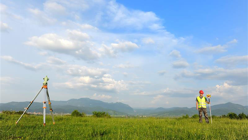
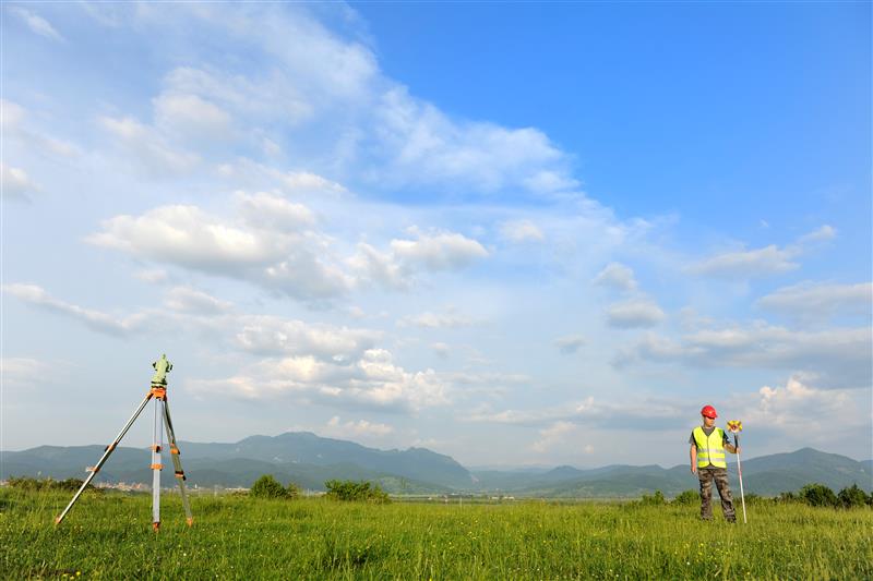
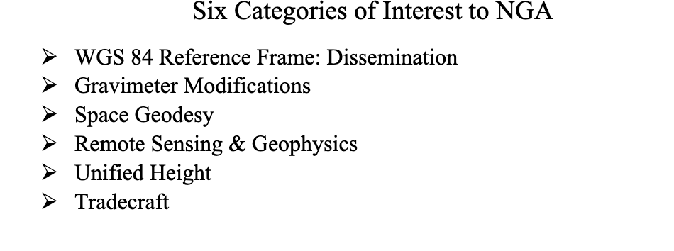

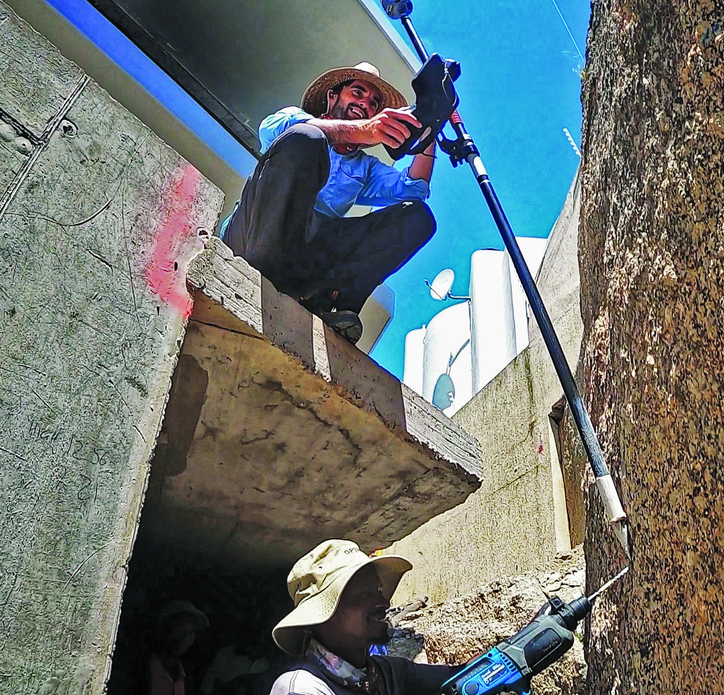
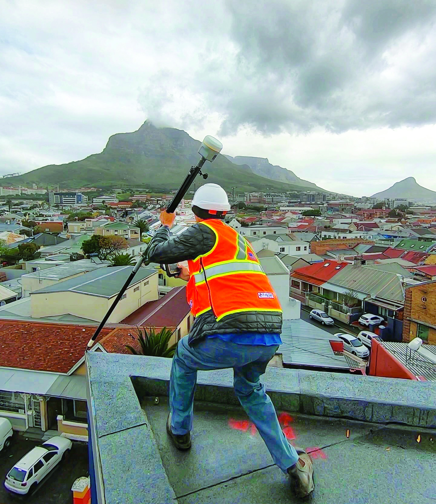
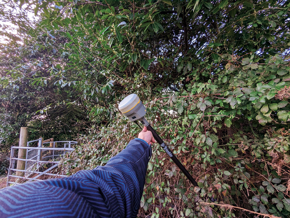
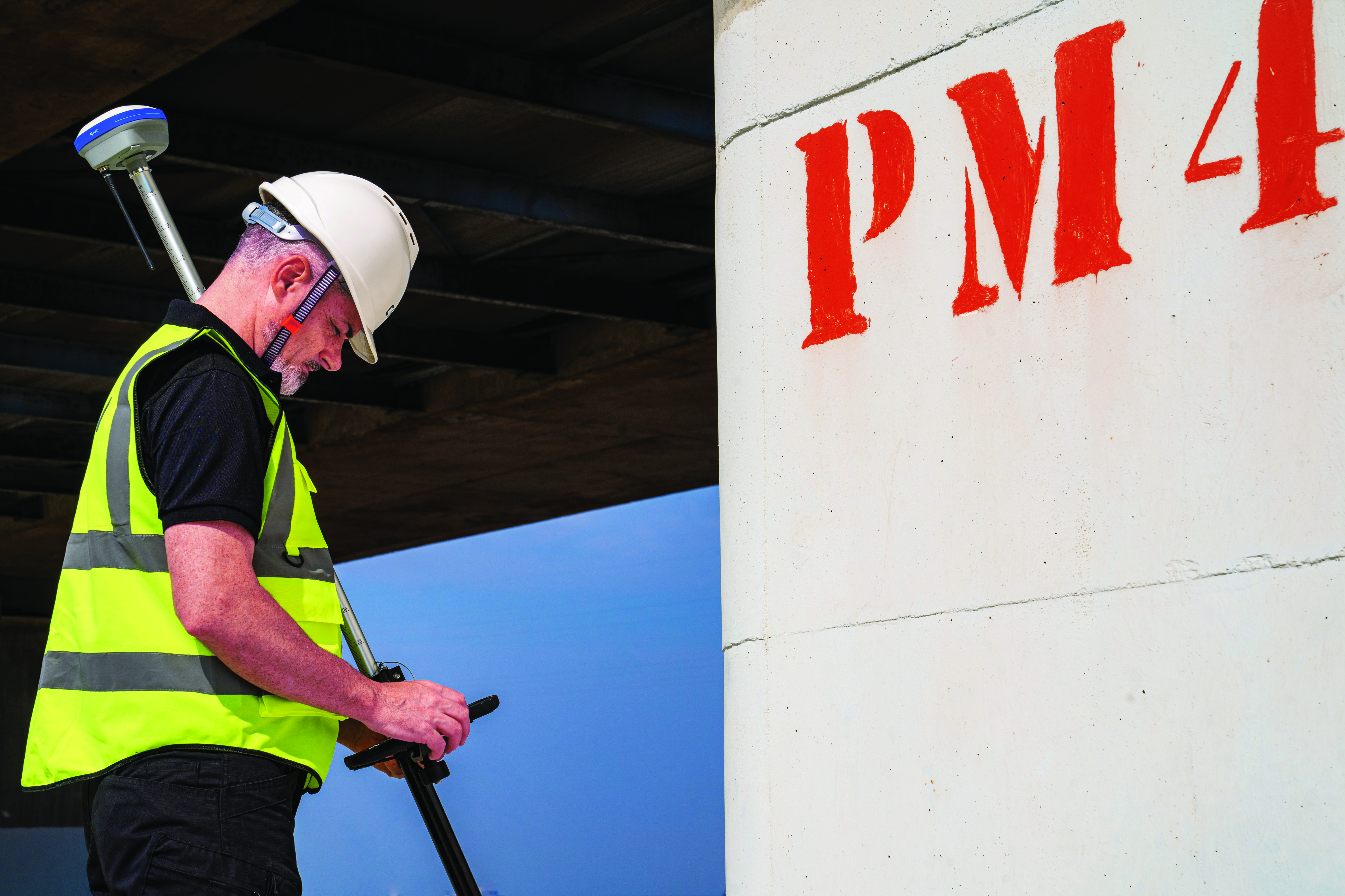
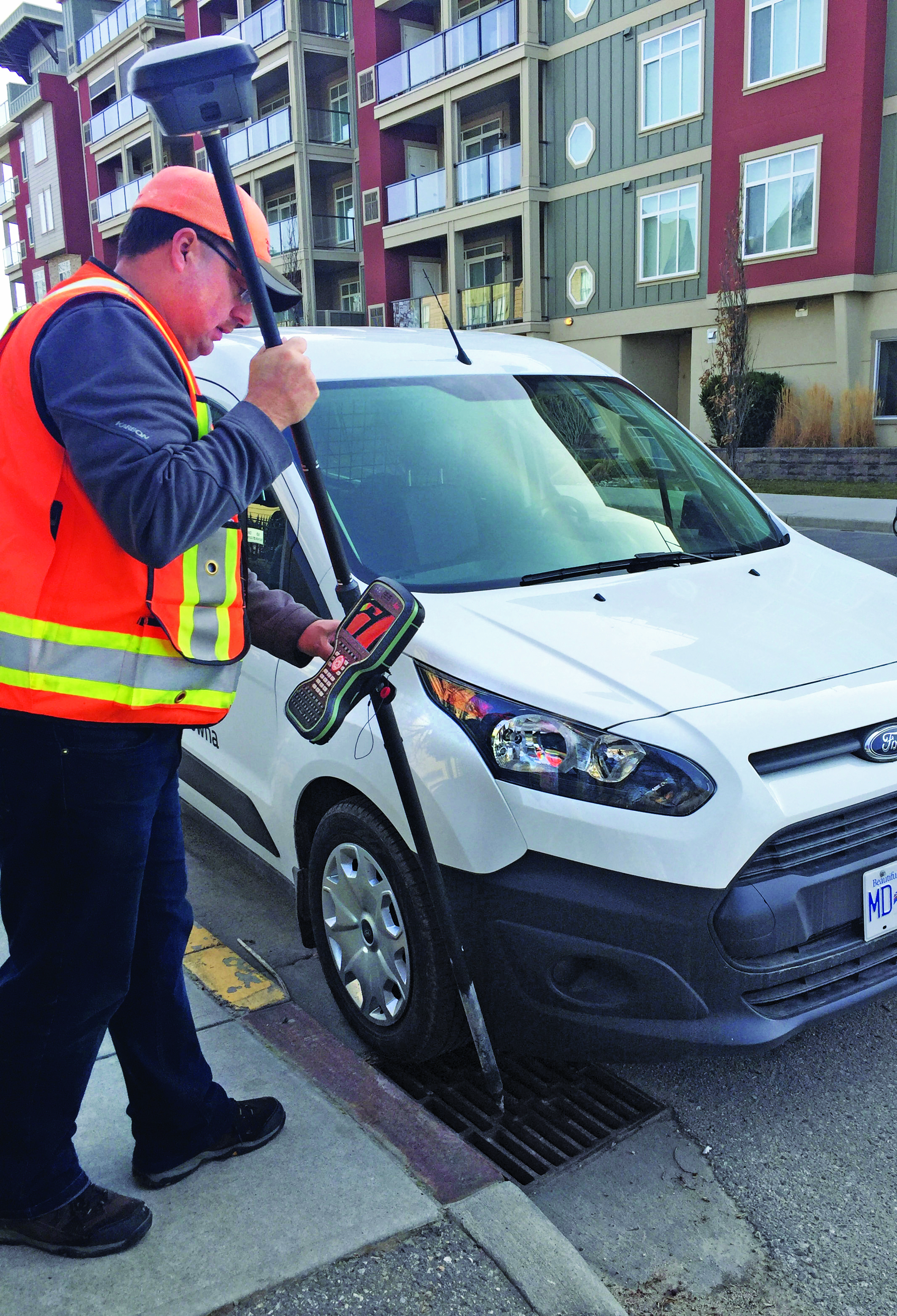
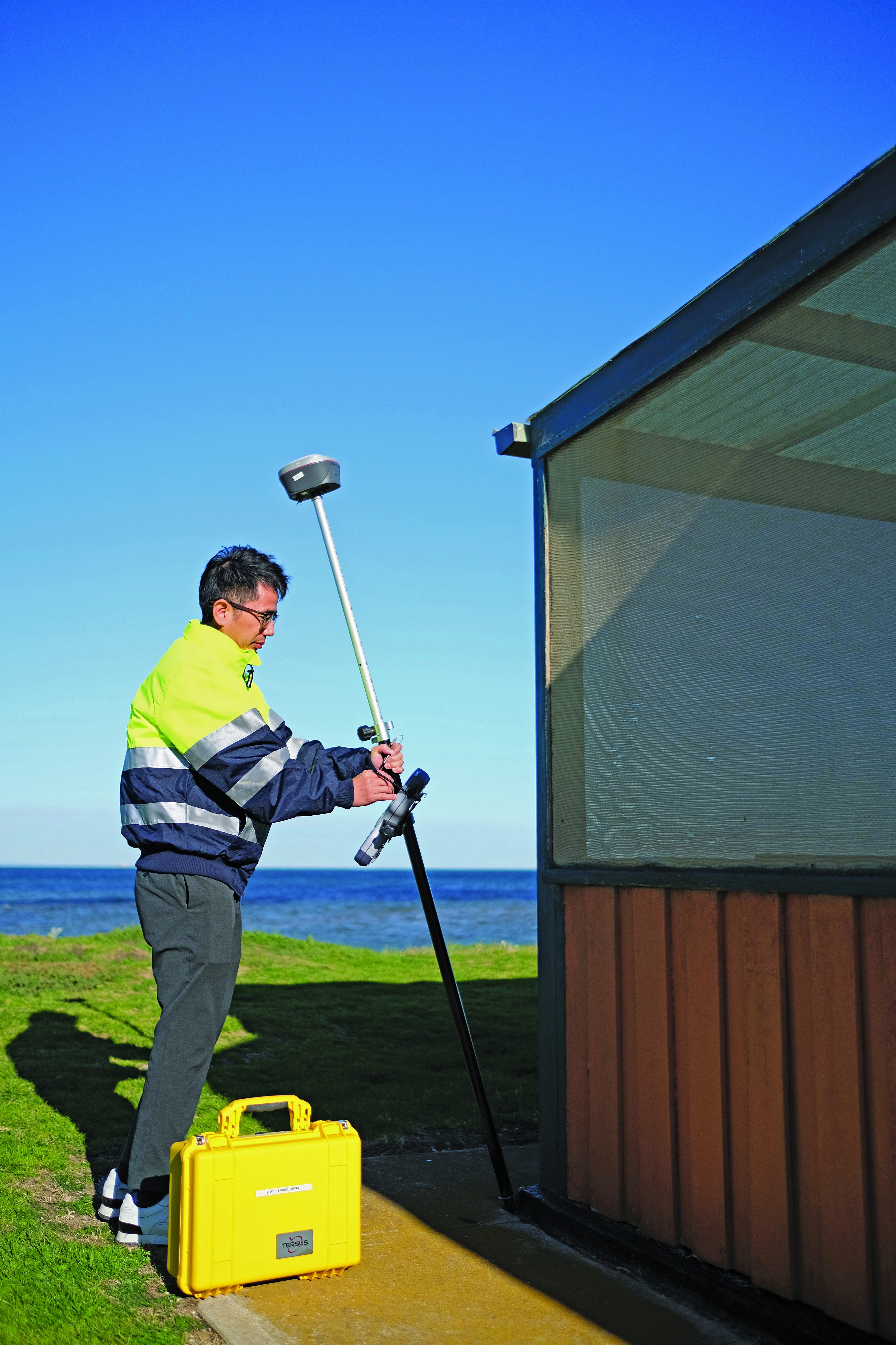
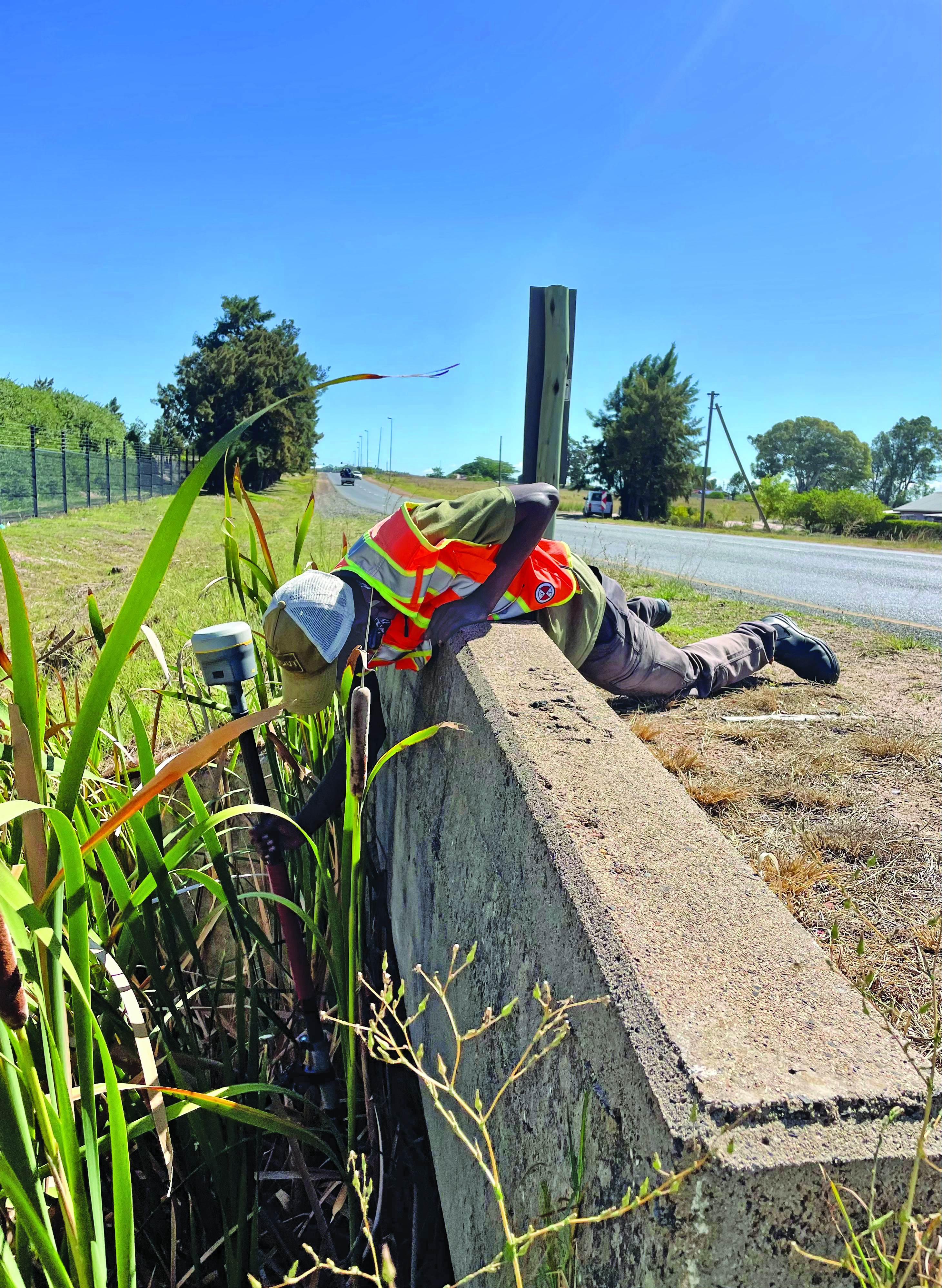
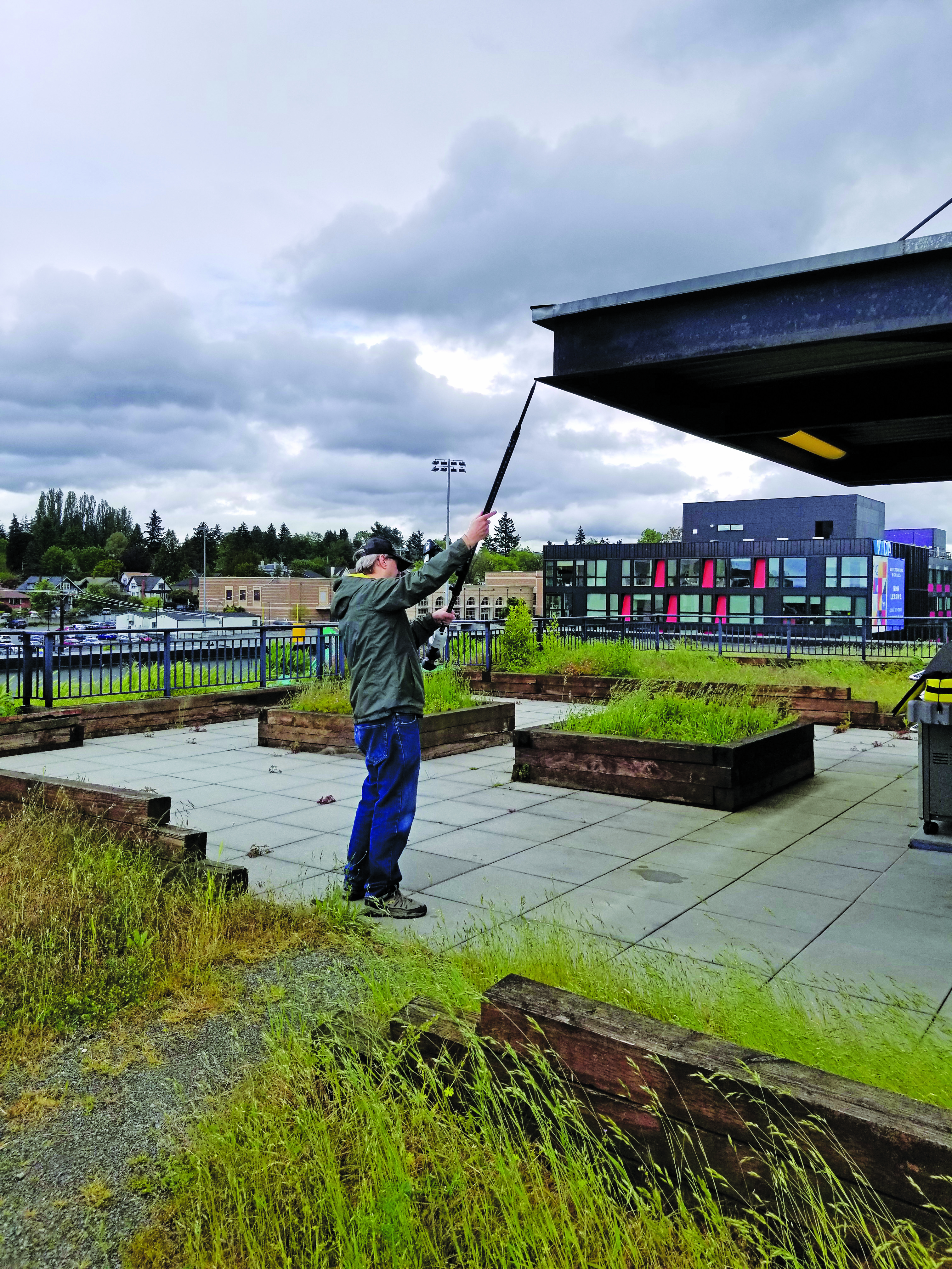

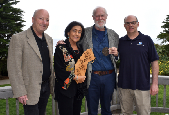

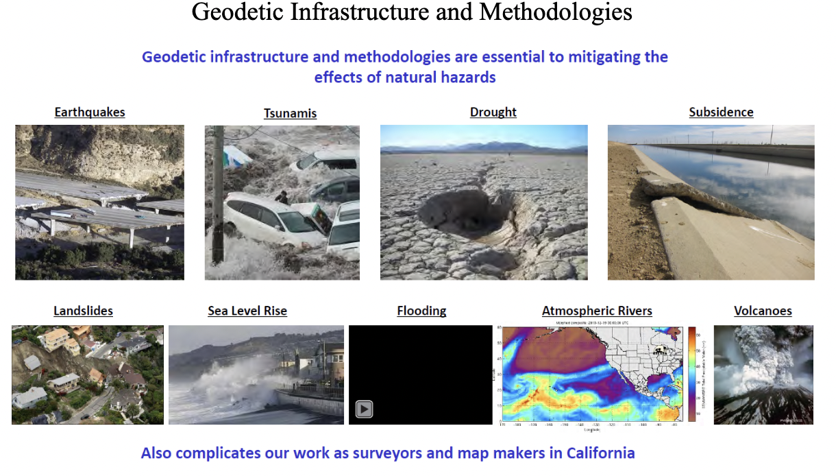
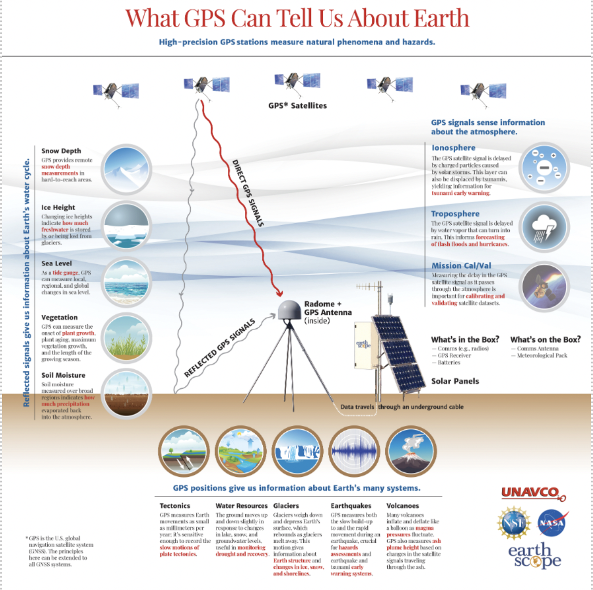
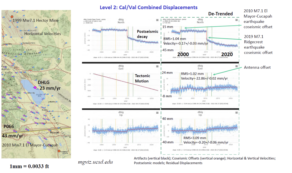
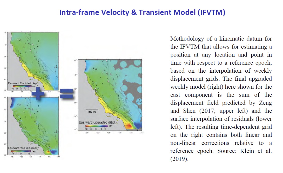
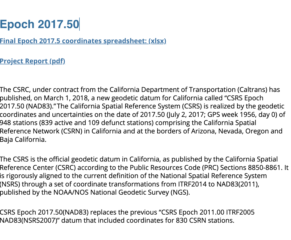
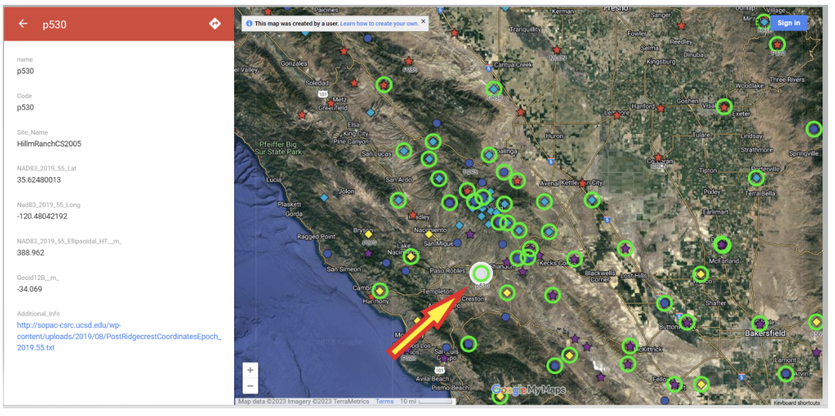
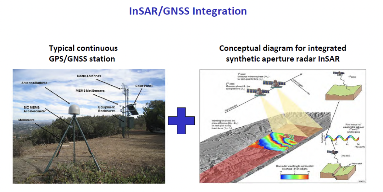
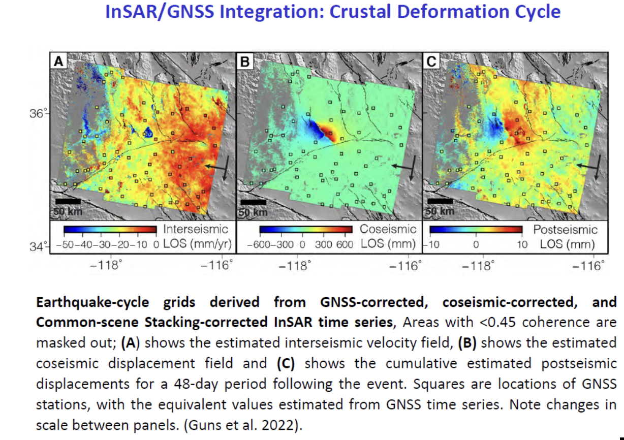
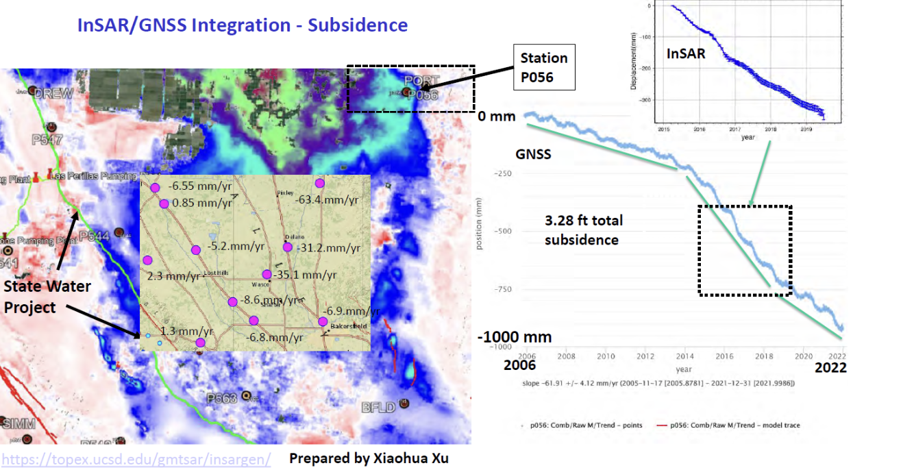
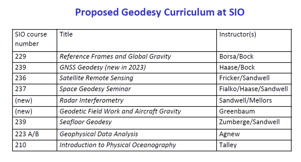

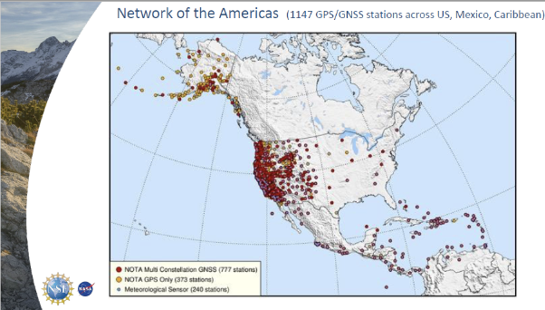
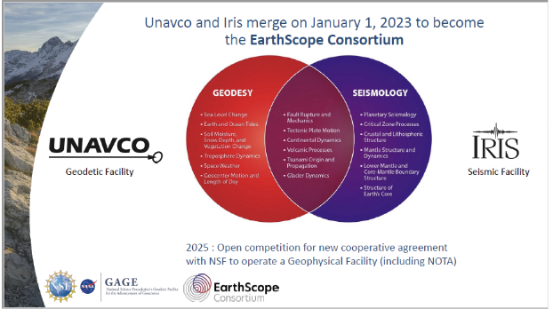
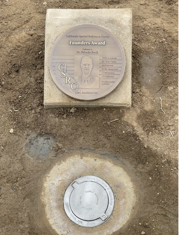

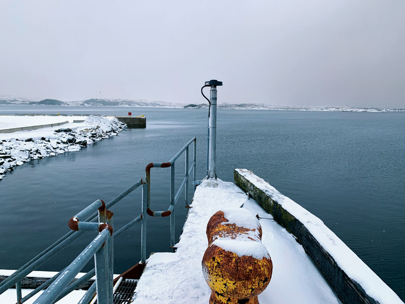
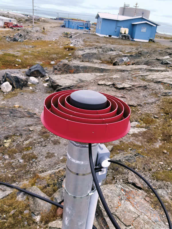
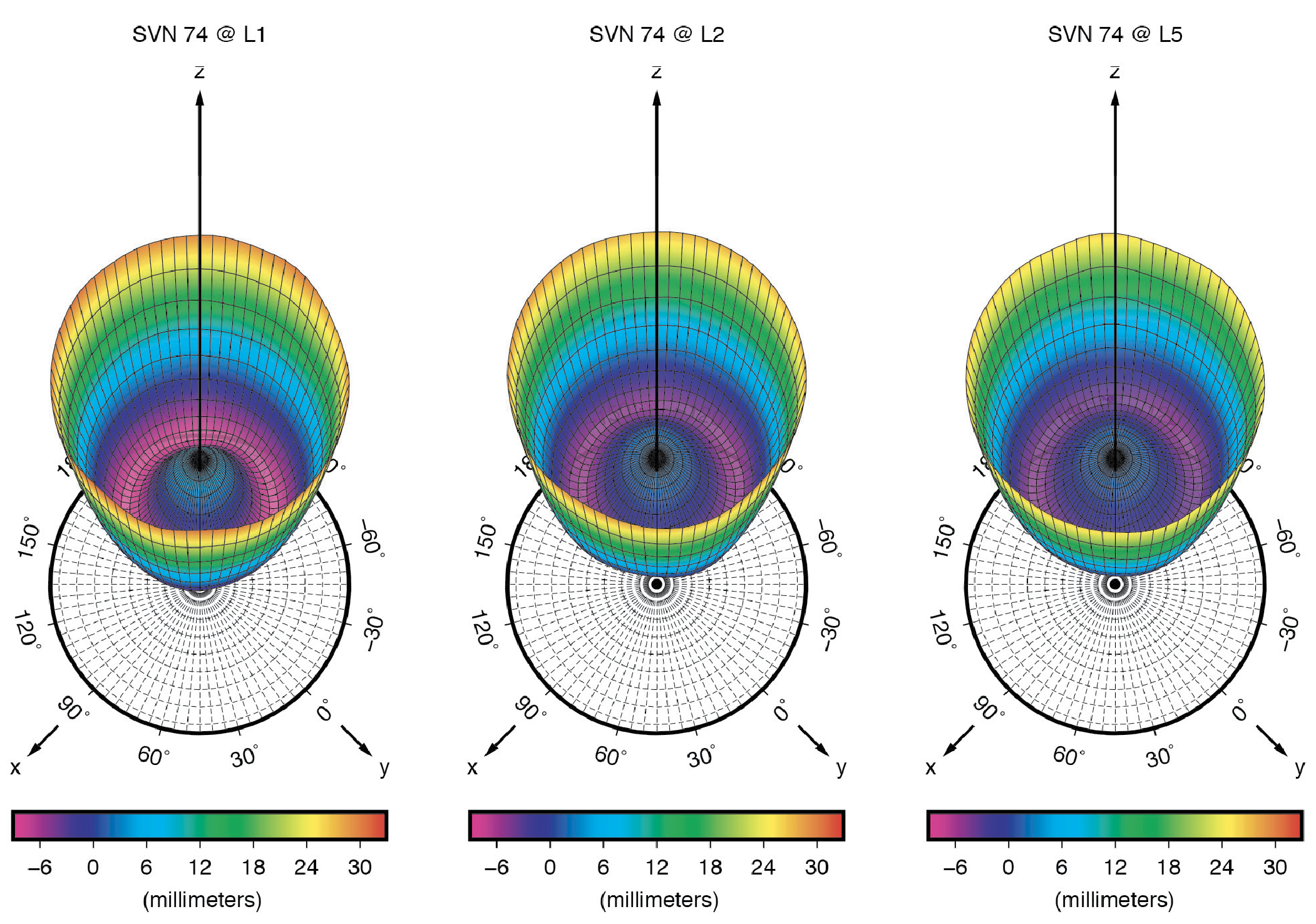
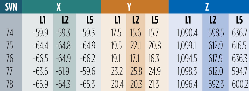
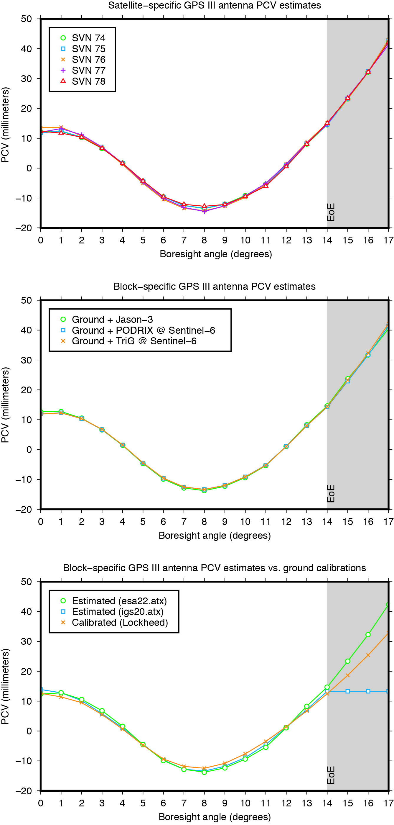
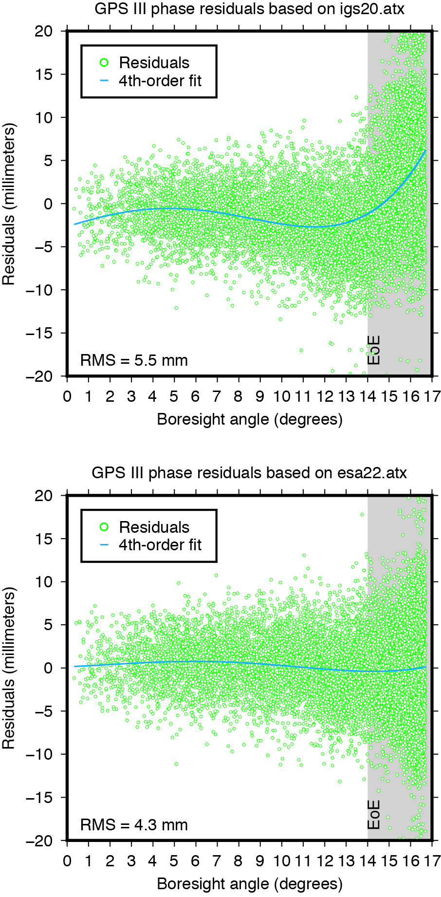
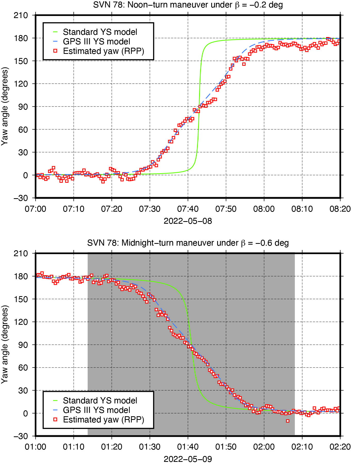

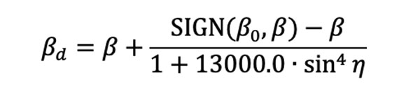
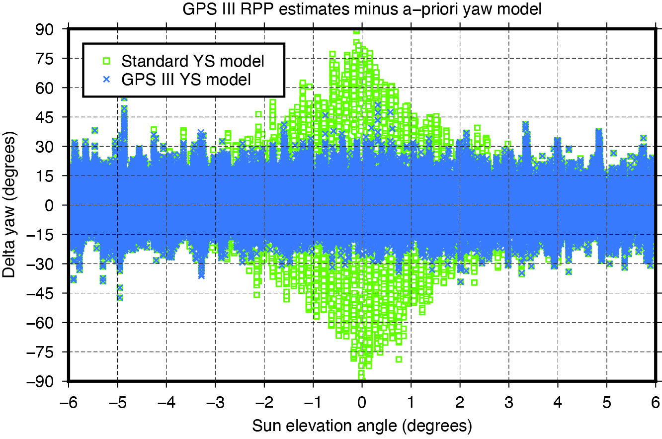
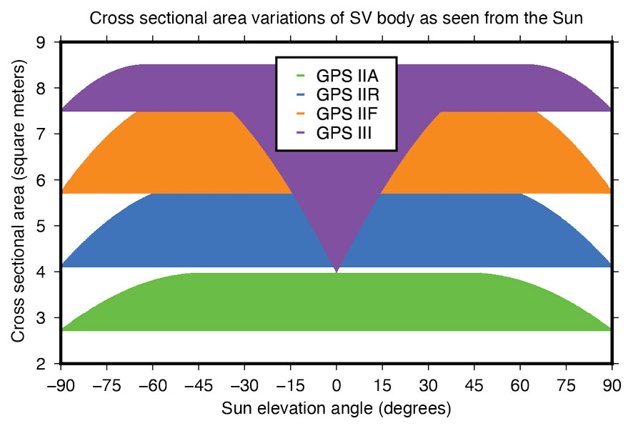
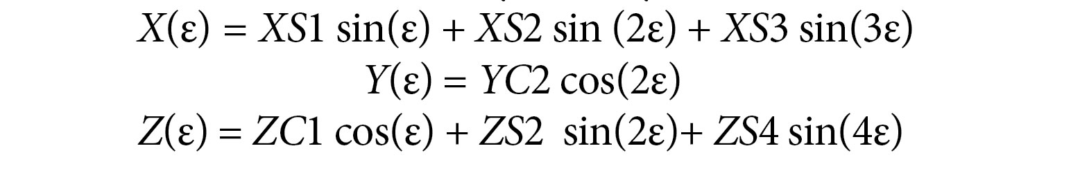
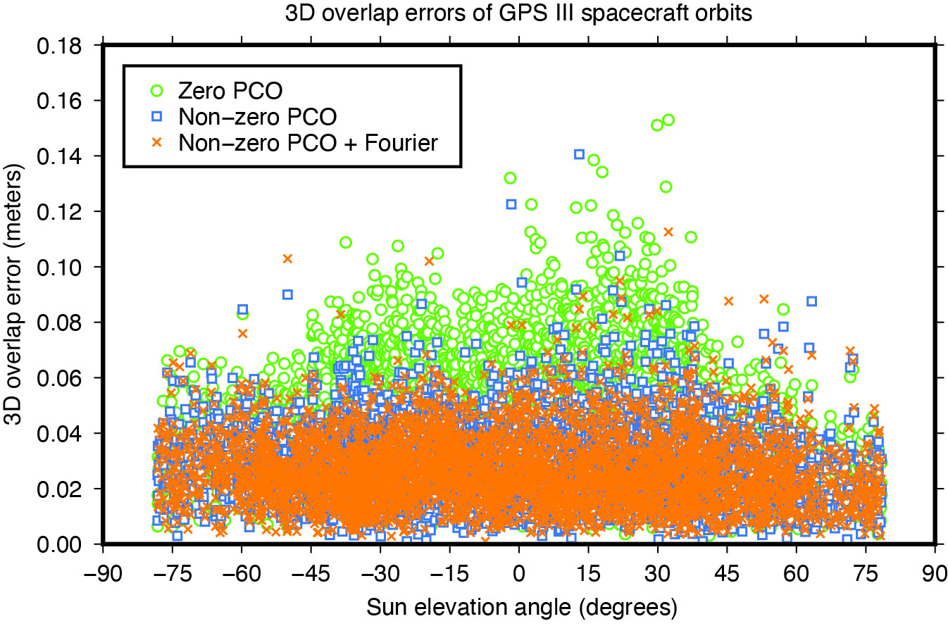
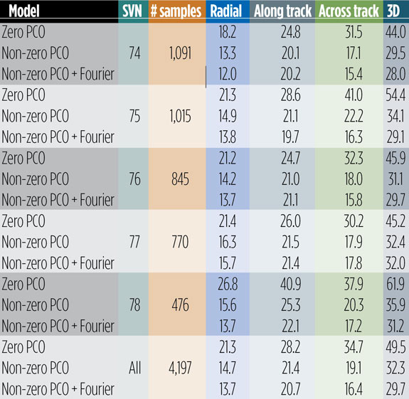
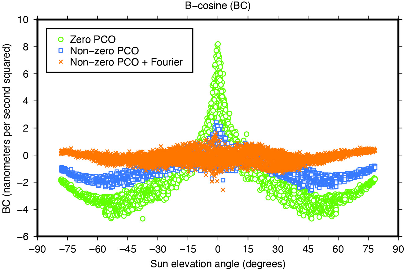
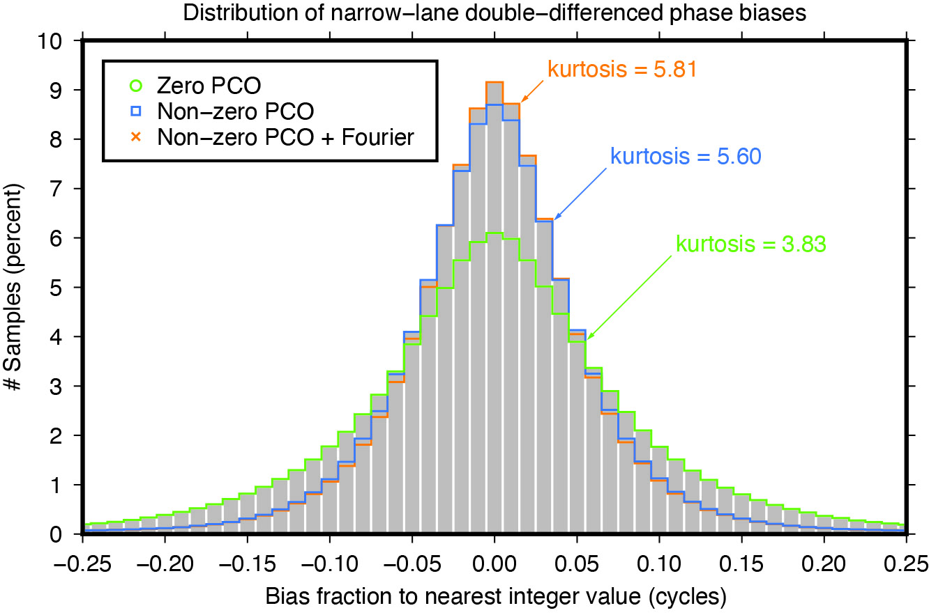


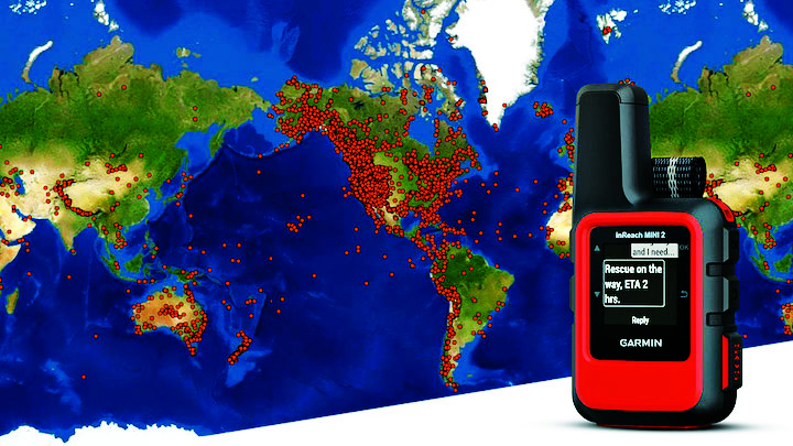
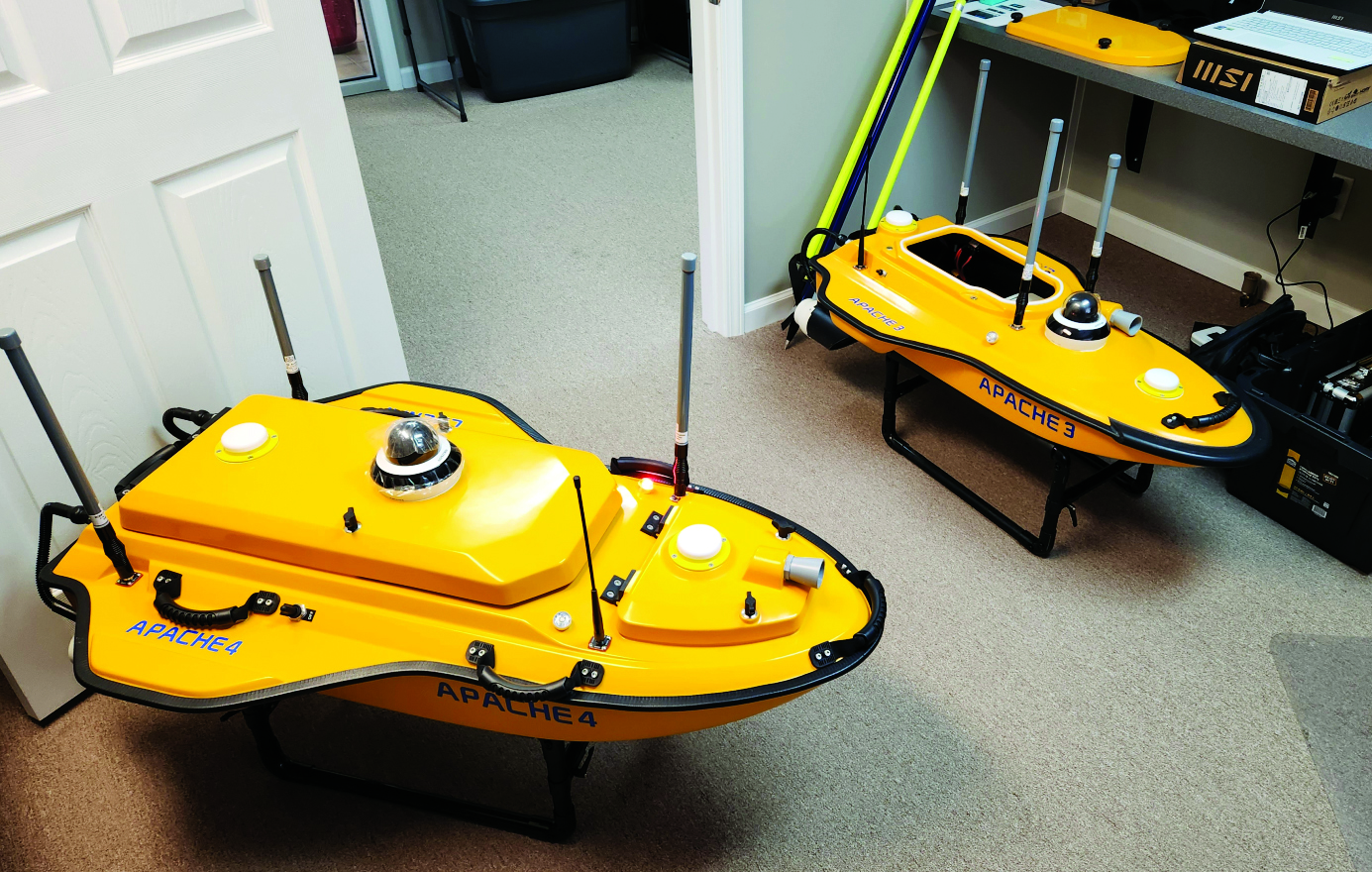
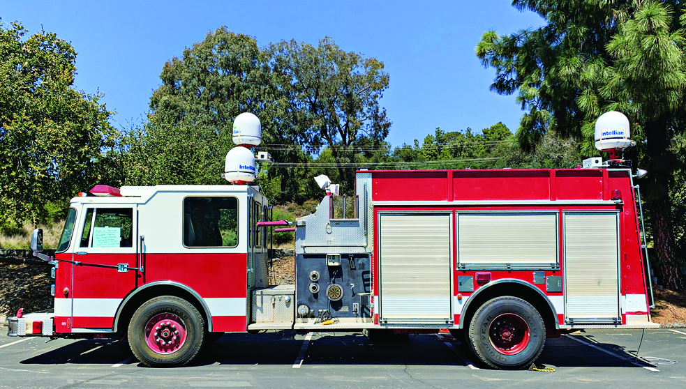

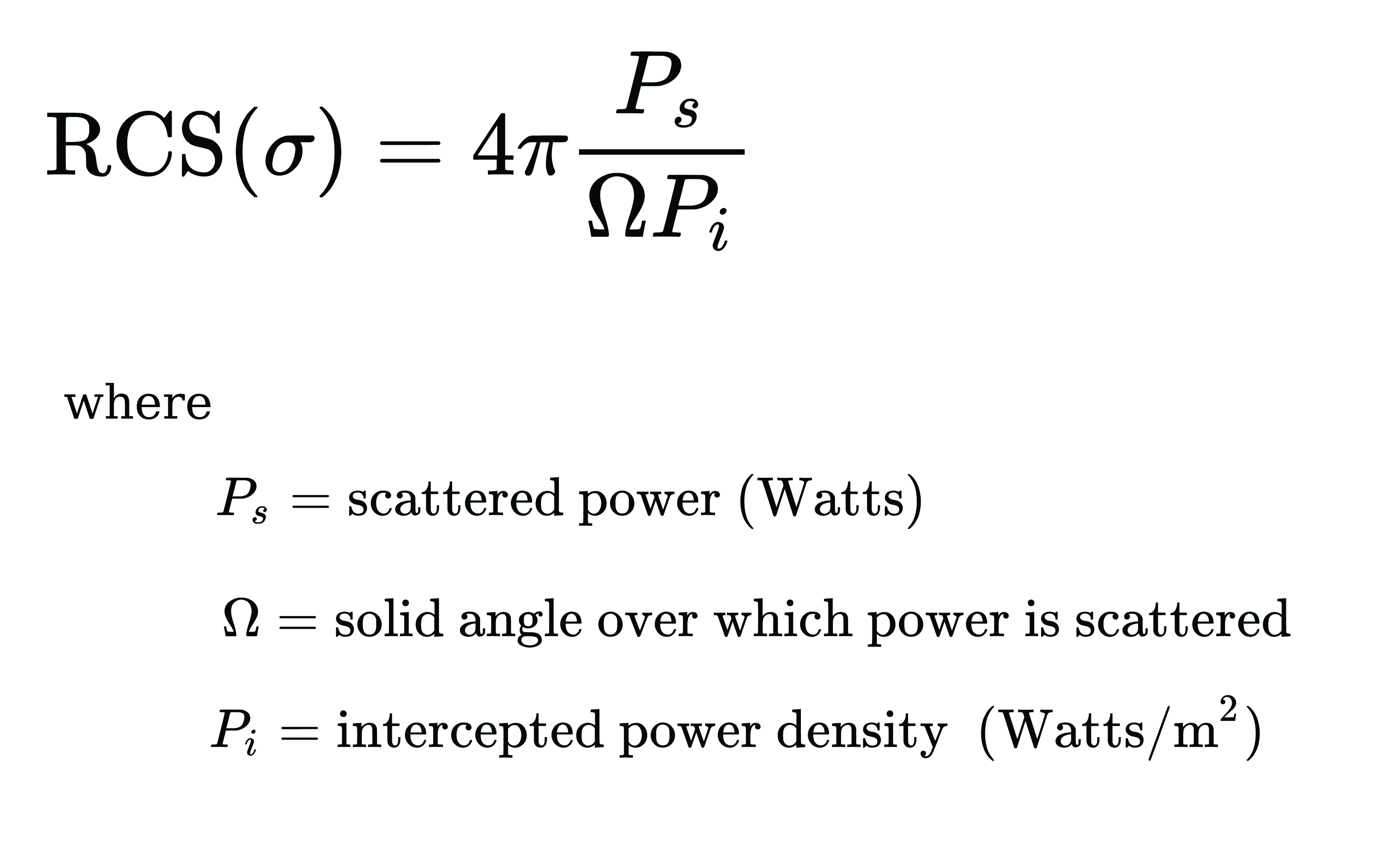
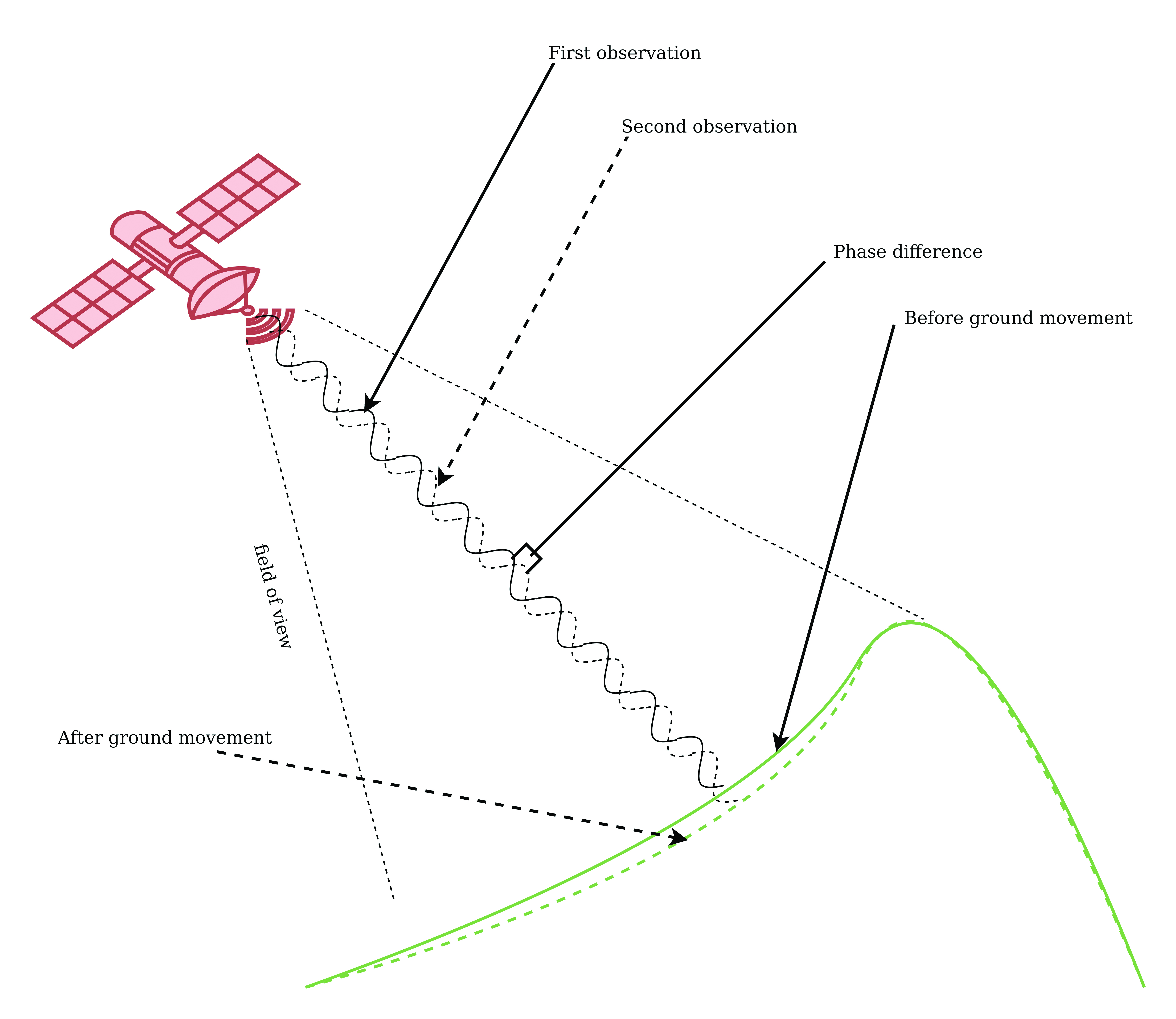
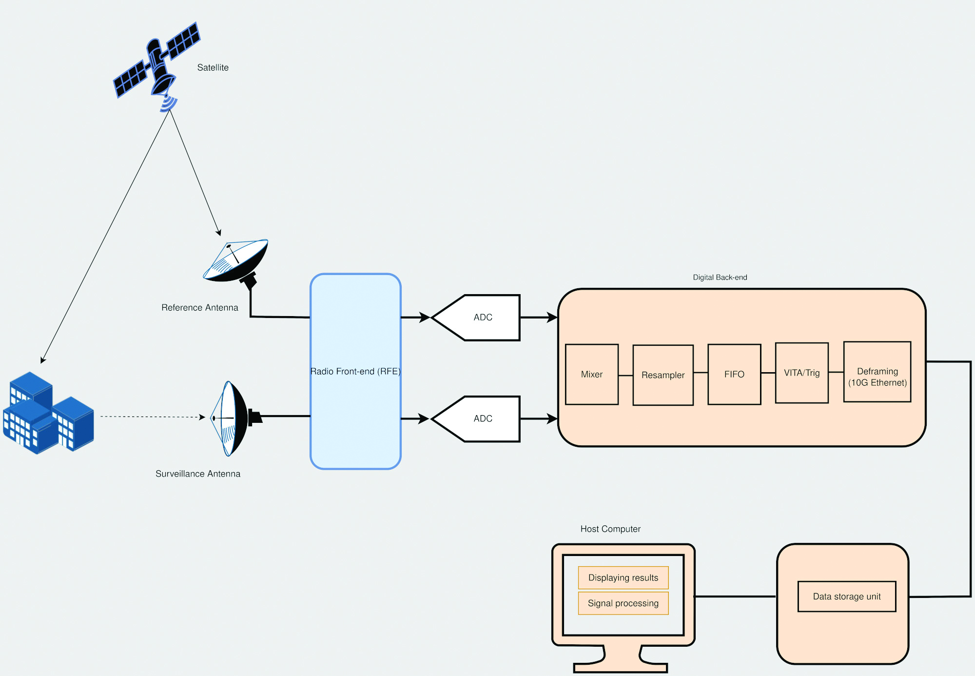