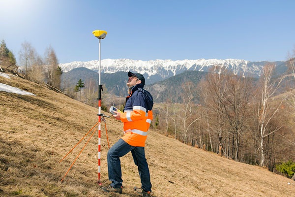
A Spirent user employs a portable GSS6450 attached to an antenna to record GPS, other GNSS, and complementary signals for resilient PNT testing. (Image: Spirent)
What is Spirent’s GPS origin story?
Spirent’s GPS genesis began on a rooftop in the middle of the night in the early 1980s. Engineers were attempting to acquire the new GPS signals with their receivers, scheduling their lives around the times when satellites would pass overhead, angling antennas off a roof in the dark, and hoping for favorable conditions. Those difficulties inspired an idea: since real-world conditions are never the same twice, simulating the signals in a lab would control variables and provide repeatable and trustworthy results.
That idea grew to be Spirent’s positioning division — a team of experts whose sole focus is to partner with customers to accelerate the deployment of robust PNT technology. In 1985, one of the first groundbreaking simulators provided to a customer generated six GPS L1/L2 signals. Soon after, we developed the world’s first simulator with SA-A/S capability, establishing our reputation for innovation. Today, simulation is for much more than convenience. The further upstream testing starts, the better for R&D and investment decisions. Because of that, we work across the spectrum in close partnership with constellation developers, receiver manufacturers, and OEM application integrators.
Can you share a recent breakthrough?
GPS regional military protection (RMP) is a nascent anti-jamming capability that uses a steerable, narrow-beam M-code signal, allowing U.S. and allied forces to operate much closer to interference without losing connection. Spirent supports RMP, so modernized GPS user equipment (MGUE) can be tested and integrated with RMP long before live-sky signals are available.
Another major breakthrough is in AltNav, a catch-all term that includes non-GNSS sources of RF and other complementary PNT, with recent attention focused on low-Earth orbit (LEO) constellations. Spirent has developed LEO AltNav simulators for both the military and commercial sectors that seamlessly integrate with Spirent’s extensive testbed for GNSS, threat simulation, inertial navigation systems, and additional complementary PNT.
How is your company preparing for the next 50 years of PNT with GPS and beyond?
As a trusted industry test partner, one of Spirent’s guiding principles over the past five decades has been to support PNT developers and early adopters by being first-to-market with new signals and constellations. Enabled by our flexible solutions, our dedication to that tenet will continue across the next five decades.
NAVWAR resilience testing is an area where emerging test needs will continue to demand more from the test environment. Layered PNT positioning engines — including GNSS, secure military signals, CRPA systems, multi-orbit architectures, and sensor fusion — are driving complexity in the test regimes that support them. Spirent’s purpose-built solutions are designed to meet these advancements, with deterministic simulation that delivers definitive validation and accurate test results.
Spirent pioneered the use of software-defined radios for GNSS simulation with the GSS9000, which enabled the same architecture to support new signal types, higher motion rates, user-defined waveforms, and more than double the generated signals. The next generation will extend that flexibility, capacity, and ease of integration to future complementary PNT sources while maintaining system performance across physical and virtual realms.
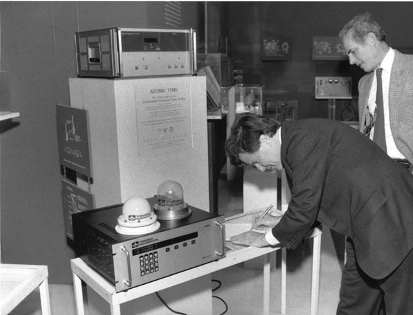
Charlie Trimble provides the 4000A GPS Locator to the Smithsonian Museum. Introduced in 1984, it was the first commercial GPS positioning product. (Image: Smithsonian)
Trimble Navigation, which had started out making Loran receivers, was looking for its next marine project when HP decided to cancel its GPS project. Budget problems in Washington put completion of GPS in doubt. However, encouraging words from Brad Parkinson were enough for Trimble Navigation to buy the canceled project.
The purchase included a stack 14-ft high of unclassified reading material and a breadboard that fit on the table of a mobile home. It was a working GPS receiver that had recorded the mobile home’s position as it was driven around freeways in the San Francisco area. It took 12 months for a team of two engineers and 15 consultants to come up with the seven breakthroughs needed for the block diagram. Trimble was to iterate this block diagram on an 18-month cycle to follow Moore’s Law cost curve to the $100 required for car navigation. It took another year to build six rack-mounted multichannel receivers.
In October 1984, Trimble sold the first receiver for $100,000. Then came the sale of 20 OEM single channel timing receivers. The oil service industry was an important early market. At the time there were only seven GPS satellites in the sky and applications were limited to 3-4 hrs/day of accurate position measurement. Accuracy was a market driver, which led to the development of differential systems. These provided meter accuracies over wide areas. The next and far more difficult step was enabling a 1st order survey — which required accuracies of 1 cm/km.
Meanwhile, next gen GPS was added to Trimble’s marine Loran-C receiver and the company produced aviation receivers for the commercial markets. In January 1986, Trimble licensed its GPS technology for the Japanese car navigation market to Pioneer.
Then came the Shuttle disaster, and a new rocket had to be designed to launch more satellites. With only seven satellites in the sky and an unknowable time for rocket development, GPS use for navigation was off the table. Getting carrier phase 1st order products to work became critical for Trimble’s survival. In May of 1986, Trimble shipped an order of seven survey systems to the California Department of Transportation (Caltrans). Earthquake monitoring was a niche market add-on. Another “bet your company” deal was a Japanese order of 25 dual frequency systems.
During this time Trimble started to realize GPS was more than a device — that time-stamping events and geo-tagging things made it a valuable information technology component. The real value was in the information. By 2000, the Hong Kong price of the GPS function in quantities of a million devices a month was $1. GPS became ubiquitous and a fundamental component of a thriving information technology market.
GPS started out as a real-time worldwide system for navigation. It is now an indispensable part of modern life. GPS has truly changed our world.
The Global Positioning System (GPS) project started 50 years ago, in 1973. I was fortunate to be part of incorporating GPS into the National Spatial Reference System (NSRS) when I worked for the National Geodetic Survey (NGS). GPS was not considered operational until 1993, but NGS started performing GPS surveys in 1983. Geodetic control surveys that formerly took six to 12 months to perform using classical methods could be performed with GPS in a few weeks using fewer personnel and resources. It changed the way NGS and others performed their surveying operations.
While one group in NGS was developing programs to evaluate and compute coordinates using GPS, another NGS group was completing the readjustment of the North American Datum of 1983 [NAD83 (1986)]. The analysis of GPS indicated that some of the latitude and longitude values estimated using GPS did not agree with the published NAD83 coordinates. The classical techniques used a triangulateration process (involving angles and distances) that required several triangles to connect two stations that were not intervisible. GPS, on the other hand, could directly measure the distance between the two stations, resulting in more accurate coordinate differences.
To support surveyors, NGS, working with other federal agencies under the auspices of the Federal Geodetic Control Subcommittee (FGCS), developed a GPS test network in the Washington, D.C., area to demonstrate whether a specific manufacturer’s GPS receiver and associated geodetic post-processing software was an accurate relative positioning satellite survey system. This facilitated the use of GPS for incorporating geodetic control in the NSRS. As mentioned above, GPS surveys exposed many inconsistencies between existing NAD83 (1986) control. Organizations such as NGS and state transportation departments that performed control surveys used GPS as soon as equipment met the federal testing requirements because it was more efficient and cost-effective than classical techniques. This led individual states to perform statewide geodetic network projects to upgrade their NAD 83 (1986) coordinates. These surveys were ultimately designated as High Accuracy Reference Networks (HARN).
In the beginning, the attitude of the individual surveyor accepting GPS was one of “trust after verifying.” Many surveyors considered it to be a “black box” that could not be trusted. Surveyors were accustomed to having angles and distances they could write down and check the results. Also, there were some key challenges and limitations of using GPS for surveying in the early days. This included the cost and size of the equipment, the peripheral devices required, the power requirements (including 12v car batteries and generators), “black box” computer processing software, obstructions near monuments, and limited visibility of GPS satellites.
Prior to GPS becoming fully operational, some surveys had to be performed in the middle of the night to have four or more satellites visible during the observing session. This required a significant amount of technical planning, which sometimes required complicated logistics for coordinating observing sessions. Also, at that time, most private surveyors did not perform control projects, so even though GPS may be more accurate, it was not more cost-effective than classical techniques for their typical projects.
Over time, after GPS became operational, more surveyors (and other professionals) embraced using GPS after the cost of receivers decreased, user-friendly processing software became available (e.g., NGS OPUS), Continuously Operating Reference Stations were densified (e.g., NOAA CORS), and statewide Real-Time Networks (RTN) were established (e.g., North Carolina RTN). GPS technology now underpins many sciences, large areas of engineering (such as driverless vehicles and UAVs), navigation, and precision agriculture. GPS (today GNSS) and its applications have changed the way surveyors and geospatial users perform their work, and the world has seen the development of applications that were not ever imagined 50 years ago.
The Air Force was initially opposed to GPS. How did that change?
Between 1978 and at least the mid-1980s, maybe even the late 1980s, the Air Force tried several times to cancel the program. At the time, I was a Capitol Hill staffer for the House Intelligence Committee. In one of those efforts to cancel GPS, Tom Cooper, who was a lead staffer for the House Armed Services Committee, came to me and said, “Can you guys give any reason for keeping GPS?” And I said, “Yes, it greatly improves the accuracy of SIGINT [signals intelligence] locations. It makes a very big difference.”
So, Tom used that, along with other arguments, for why we should keep GPS. The Committee and Congress ultimately decided they would, despite the Air Force’s resistance.
The Air Force’s resistance came from the Strategic Air Command, which in the 1980s believed it would never use satellites. They were concerned about the satellites being shot down. I found this amusing because they were flying around in aircraft at a few thousand feet and were concerned about satellites flying at 11,000 miles. But they were, so they were laggards.
Image: USAF/Staff Sgt. Kyle Johnson
Which service adopted GPS first and why?
The service that by far led the way was the Army. It spent $100 million a year absorbing NRO capabilities. They also spent money on GPS, though not as much. By the time we got to the first Gulf War, in 1991, we had a partial GPS constellation — I think of 18 satellites of the 24 required — and that meant that you didn’t have 100% coverage all day long. So, coverage maps of their areas of interest were generated every day to let people in the field know when they would have service. Most of them didn’t have receivers either. Most of the receivers they did have were Precision Lightweight GPS Receivers (PLGR), knows as “pluggers”, which were the first “handheld” receivers, but they were pretty big.
Once the fight got going, many of the troops wrote home and asked their moms and dads to send them civilian receivers.
Yes! Thousands and thousands of them showed up in theater. Some troops taped them to the windscreens of their helicopters or jet aircraft. They were just jury-rigged into everything because, despite their limitations at the time, they were very, very useful, unlike anything else. So, now everybody realized, “Oh my goodness, this is really a big deal. This is a game changer!”
Then we got more modern receivers, integrated receivers, the whole thing. However, at the end of the Gulf War, the Air Force still had no plan to equip any of its aircraft with GPS. As Assistant Secretary of the Air Force, I was called over to the Armed Services Committee and asked, “What is your plan for integrating GPS receivers into your aircraft fleet?” I said, “There is no plan.” and they were incredulous. They looked at me like “Well, you’re an idiot.”
It wasn’t me, however, and the staff knew my story before I gave it. As a result, Congress mandated it. They put it in that year’s National Defense Authorization Act (NDAA). Within less than 10 years you had Joint Direct Attack Munitions (JDAM) and other GPS-guided weapons. So, that got it moving quickly.
By the end of the 1990s, the Air Force was fully on board and were equipping their aircraft with many weapons that depended on GPS. Meanwhile, GPS had moved to a full constellation of 24 satellites. Full operating capability was declared in 1995. The Navy proceeded similarly, but they were somewhat less affected. So, the Army remained a leader in using space.
The Chief of Staff of the Air Force asked me about Air Force use of GPS. I said, “Chief, the Air Force builds a lot of space stuff, but it doesn’t use it.” Of course, a short time later it was using it extensively. So, this ramp-up was very rapid — just a few years from “I don’t give a darn about these things” to “I can’t live without them.”
Brad Parkinson and his successors as JPO directors designed and built the system but had no role in its adoption, right?
No. They were going turn it over to the production house, if you will, and they did. Once the Air Force got on board with GPS guided weapons, adoption proceeded rapidly.
What about the Navy?
I don’t recall the Navy particularly. I do not at all accuse them of being laggards. I think they did what they needed, whatever that was.
Did later NDAAs expand that mandate to the other services?
I don’t know. I was out of the government by that time, so I lost track. I don’t think it was necessary. What people didn’t understand immediately was that you could do anything with this system. At the end of the day, it is a super accurate timing signal. There are many things you could do with that and people have done them. It quickly became evident that it was so pervasively useful, that anything you could think of involves GPS, from the era of the first Gulf War onward. By 10 years later, many weapons systems in all the services were GPS-guided. I later served on the board of ATK and we were building GPS-guided artillery rounds. I am pretty sure that the ATACMS [Army Tactical Missile System] you hear about today is GPS guided.
So, in a couple of years, all the services wanted to integrate GPS in all their platforms and weapons.
Well, except that the amazing thing was, despite all the things that people had done with GPS in the Gulf War — starting with those helicopters that went in the first night and took out the command and control system, which were guided by Army-provided pluggers taped onto the windscreens by their pilots, and downed pilots using GPS to give their coordinates to the rescue teams — at the end of the war the Air Force still didn’t have a plan to put them on its aircraft! That’s when Congress mandated it. It was amazing.
Despite that, once they got going, particularly once they got going with GPS-guided weapons, everything changed. I don’t know whether the Air Force became leaders, but they were certainly aggressive integrators of the program into the service. There was no more, “We won’t use satellites” and all that.
That was after my time. I left government in early 1993. There were other big fish to fry at the same time. As important as I realized it was, I still didn’t realize how important it was, and I was way ahead of most everybody else, in the Air Force anyway.
The Federal Aviation Administration’s (FAA’s) chief scientist at the time said, “The great thing about GPS is that it is a tool around which you can build myriad capabilities.” He outlined a few for the FAA, many of which they have since done. The same thing began to happen in the services, particularly in the Air Force, in which GPS-guided weapons were pervasive within 10 years.
Part of Brad’s motto for JPO was “The mission of this program office is, number one, to drop five bombs in the same hole.”
Yeah. By the way, one mistake that people make a lot is they think there were GPS-guided weapons during the first Gulf War. That was not the case. There were none by then. There were precision guided munitions that were guided by maps and lasers and a variety of means. But, despite the belief of many authors, there were no GPS-guided weapons at that time.
So, which was the first conflict in which GPS was used?
It was the Iraq War, in 2003. It was a major user of GPS-guided weapons.
Any other thoughts on the 50th anniversary from the military side of things?
It is impossible to overemphasize the importance to military operations and, frankly, to civilian life as well, of being able to easily and accurately navigate or have highly accurate time.
You can do it with a $100 receiver, whereas it used to require a $10,000 receiver and you had to have it re-initialized from a standard. So that’s what everybody does. Now, this has created probably more dependency than is healthy and many nations have backup that we don’t have.
Such as Loran-C. That’s a big subject of debate these days, as you know.
Well, it’s been a subject of debate for 20 years. Everybody agrees, but nobody moves.
The Department of Transportation recently released an action plan on the adoption of complementary PNT systems. So, there’s some movement.
As a one-time government bureaucrat, what you do when people are on your back is launch a study and say, “Well, it will be done in a year or two.” They have done this time, after time, after time.
“I know where we are. I do not need a satellite system to tell me!” In the 1970s and 1980s, this was the number one military and civilian response to what GPS does. The existing military hardware included navigation systems and the defense industry had a vested interest in keeping its business. Civilian interest in GPS was low because of the program’s uncertain funding. The armed services saw no reason to add a new program to their budgets and were opposed to GPS.
The military program approval process was also inconsistent with the rapid changes in digital technology. The first GPS satellite was launched in February 1978, the first PC was released in August 1981, and the first Mac in January 1984. GPS went through a development process to build user equipment, test it to make sure it met military requirements and then build the limited-rate production equipment with a design about six years old.
Early GPS Manipack worn by JPO Army deputy Lt. Col. Paul Weber. This photo graced the cover of the first ever GPS brochure. (Image: GPS World archives)
My favorite joint service story is that our low cost, 19-lb, $55,000, hand-carry man pack flunked its first testing sequence. The Army placed it into an alkaline bath in September 1985, that ate the o-ring and caused it to fail the bio/chem decontamination requirement. The o-ring was an Air Force requirement because at 60,000 ft without venting the device would become a potential bomb. Yet, pressure relief failed to meet the Navy Seals’ requirement for underwater operation. The fixed man pack was now our limited rate production set. Developments in digital technology during the process made it overweight, over cost and unsuitable. To get hand-carry receivers, it became necessary to purchase modern civilian sets at the unexpected outbreak of the First Gulf War in 1990.
JPO ran a competition for 200 civilian receivers that had no military requirements to send them to the operational forces for training. Trimble won the competition and when the war came the following year with only 12 GPS satellites operational, JPO asked Trimble to deliver as many sets as it could produce at the price bid for the competition to augment the deliveries of the limited rate production military set. Talk about an operational education! The Army tank drivers who did not want GPS because “The war comes to us, so we do not need GPS” instantly demanded GPS receivers when they began to get lost by more than 10 miles on the featureless desert. The deployed troops began asking their parents for GPS receivers for personal use. The war integrated GPS into all military operations.
Realizing the value of GPS inter-service integration of forces, the military believed the civilian signal should only have degraded accuracy. But in May 2000, President Clinton decided the civilians also should have good accuracy and ordered that the degradation of the civilian signal (called Selective Availability) should cease. Today everybody is aware of what GPS provides. You never hear anyone say, “I know where I am, I do not need satellites to tell me.”
Originally developed for navigation and timing applications, signals from global navigation satellite systems (GNSS) are now commonly used for geophysical remote sensing applications, including observation of Earth’s surface and atmosphere using near sea-level ground stations as well as mountaintop, airborne and spaceborne platforms. GNSS reflectometry (abbreviated GNSS-R), which is the technique of using reflected signals to measure properties of Earth’s surface, has been a growing area of research and application for GNSS remote sensing. Notably, the Cyclone Global Navigation Satellite System (CYGNSS) satellite mission produces delay-Doppler maps (DDMs) that are used to monitor ocean surface wind speeds during hurricanes. Meanwhile, terrestrial and airborne GNSS-R has been used to monitor soil moisture, snow depth and vegetation growth. One area of increasing interest is precision reflectometry using signal carrier-phase measurements. The first attempt to perform precision (phase) altimetry over sea ice using GPS reflectometry measurements from the low-Earth orbiting TechDemoSat-1 was reported by researchers in 2017. Subsequently, researchers demonstrated the use of reflections collected by a Spire satellite to perform altimetry over Hudson Bay and the Java Sea and how reflections off ice in the polar regions can be used to measure ionospheric total electron content over the polar caps. While these demonstrations of GNSS-R for precision carrier-phase-based reflectometry are promising, more work needs to be done to characterize when carrier-based altimetry is feasible and what challenges it faces.
To study the challenges associated with processing reflected and low-elevation-angle radio occultation signals, the University of Colorado (CU) Boulder Satellite Navigation and Sensing (SeNSe) Laboratory has deployed a GNSS data collection site on top of Mount Haleakalā on the island of Maui, Hawaii. Recent collection campaigns aim to use this site as a testbed for GNSS-R algorithms that utilize multi-frequency and multi-polarization measurements. Previously, we carried out delay map processing for left-hand circular (LHC) and right-hand circular (RHC) polarizations for L1 and L2 GPS signals. Those results validate the open-loop processing methodology and provide an initial assessment of the data quality. We observed that the received reflected signals show deep and rapid fading in amplitude. In the work reported in this article, we extend our assessment to triple-frequency GPS (L1CA, L2C, L5Q) signals and document our methodology for extraction of the signal carrier phase. Our initial results indicate that coherent signal phase extraction is challenging, and may not be feasible for this particular experiment setup. We discuss ways in which the experiment may be improved for the purpose of obtaining coherent ocean surface reflections in the future.
EXPERIMENT BACKGROUND
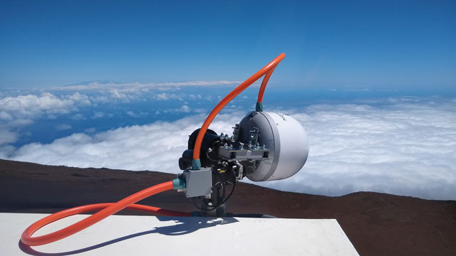
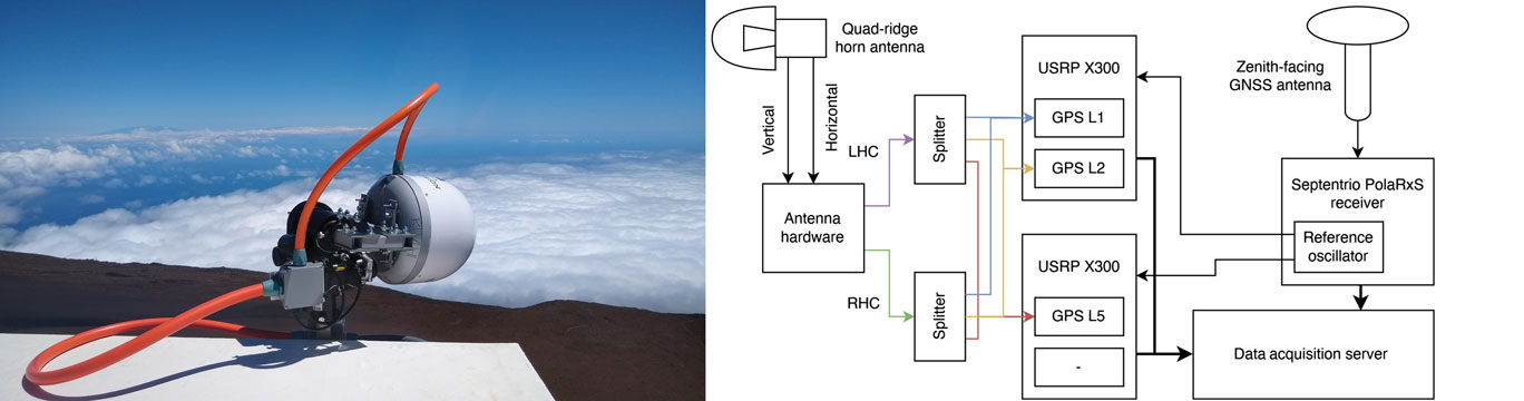
The current form of the CU SeNSe Lab Mount Haleakalā GNSS experiment was deployed in June 2020. It consists of a side-facing dual-polarization horn antenna, which is shown in the left panel of FIGURE 1, along with a zenith-facing reference antenna. The horizontally- and vertically-polarized wideband signals from the horn antenna are fed into front-end hardware and are combined using 90-degree phase combiners to form LHC and RHC polarized signals, which are then recorded by a set of Ettus Universal Software Radio Peripherals (USRPs). Meanwhile, the signal from the reference antenna is sent to a Septentrio PolaRxS receiver. The right panel in Figure 1 illustrates the system setup. Note that the Septentrio onboard oven-controlled crystal oscillator is used to drive the USRPs. This allows us to use the Septentrio outputs to estimate the receiver clock variations and use them in the receiver clock component of our open-loop models, which we discuss below.
Figure 1: The side-facing horn antenna in its radome enclosure (left panel) and the hardware block diagram of the data collection system (right panel). (All figures provided by the authors)
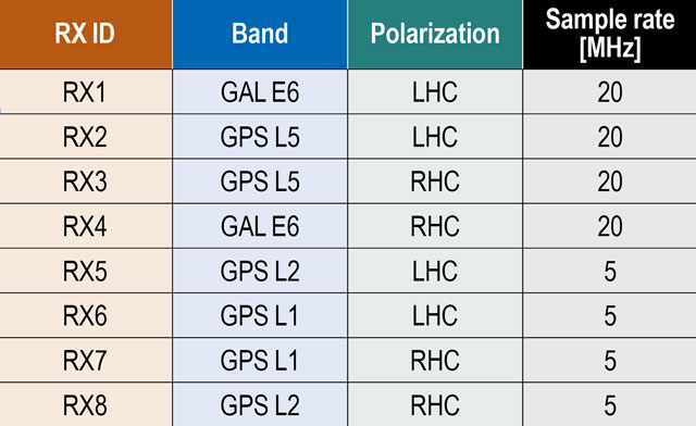
Each USRP can record up to four signals at two different mixdown frequencies, allowing for recording of both the RHC and LHC polarized signals on up to four different bands. The first USRP records the L1 and L2 bands with center frequencies at 1575.42 and 1227.6 MHz, respectively, at a bandwidth of 5 MHz. The second USRP records the L5 and E6/B3 bands at center frequencies of 1176.45 and 1271.25 MHz and at a 20 MHz bandwidth. TABLE 1 lists the IDs for each receive channel along with its corresponding band, polarization and sampling rate. Note that the recorded signals covering the E6 band also capture BeiDou B3 signals, but we restrict our analysis to GPS L1, L2 and L5 signals in this article. The samples from these USRPs are written to disk along with the Septentrio Binary Format (SBF) output of the PolaRxS receiver.
Table 1: Receiver IDs with corresponding band and polarization.
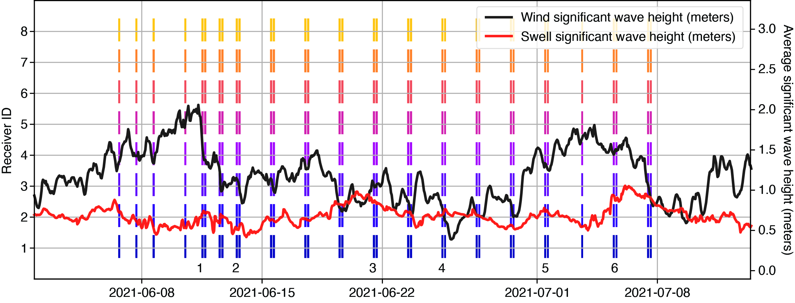
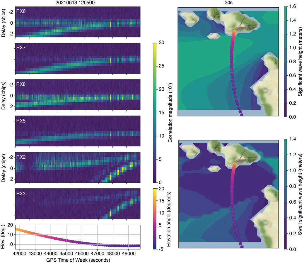
Starting in June 2021, periodic collections were taken for around one hour at a time, which is about the amount of time it takes for a GPS satellite to pass from an elevation angle of 0 degrees to one of more than 20 degrees. The collection times were adjusted to target the passes of satellites whose specular reflection point passed within the azimuthal range of the horn antenna, which faces roughly to the south and has a beam width of around 60 degrees. FIGURE 2 summarizes the available datasets from the first month of collections. The right-most panels of FIGURE 3 show examples of the specular track for GPS PRN 6 as it sets over the horizon on June 13, 2022, at around 12:00-13:00 UT. This is the pass on which we focus in this work, since PRN 6 transmits the L1CA, L2C and L5 signals and consistently had a specular point in our region of interest.
Figure 2: Available data during the first month of collections. The average significant wave height in the region south of Haleakalā is also plotted. Numbers near the bottom indicate the datasets analyzed for this article.
METHODOLOGY
Our processing method for open-loop tracking of the reflected GNSS signals is based on our previous work in which we produced DDMs and delay maps of the signal-to-noise ratio (SNR) measurements for multiple signal frequencies and received polarizations.
Pseudorange Model. We start by generating a model of the pseudorange for both the direct and reflected signal. The model only needs to be accurate down to the chip level, since we correlate across several chips of delay for the received signals. Setting a somewhat arbitrary accuracy requirement of 0.5 chips (equivalent to a delay of around 150 meters for L1CA/L2C or 15 meters for L5 signals), allows us to ignore path delays from the ionosphere and troposphere, which should only account for up to several meters of delay. The model has three terms that we estimate relative to GPS System Time (GPST): the receiver clock error, the satellite transmitter clock error and the geometric range. We use a surveyed position of the horn antenna along with International GNSS Service precise orbit and clock products for the transmitter clock error and positions. These allow us to compute the transmitter clock error and path delay for the direct signal. The reflected signal path delay can be found by computing the specular reflection point on the WGS84 ellipsoid and adding the distances from the transmitter to the specular point and the specular point to the receiver. The remaining term to estimate is the receiver clock error. Recall that our USRPs are driven by the Septentrio internal oscillator. Therefore, the clock error in Septentrio measurements is associated with variations in the reference oscillator for the USRPs. We utilize a geodetic detrending technique to estimate these clock variations and apply them to our pseudorange model. To construct the full receiver clock error, we estimate the time-alignment of the samples near the beginning of the collections to GPST by tracking one minute of a strong, mid-elevation-angle satellite and decoding its timing information. This provides us with an estimate of GPST at the start of the file, which we can use to construct a full estimate of the GPST at any sample in the file. Also, given our pseudorange model, we can find the received code phase and the Doppler frequency.
Figure 3: Example of delay maps from GPS PRN 6. The panels to the left show delay maps for the L1CA, L2C and L5 signals, both RHC and LHC polarizations. The bottom panel shows the corresponding elevation angle over the duration of the pass. The maps to the right show the specular point location during the pass, along with a contour of the WW3 model for significant wave height and swell-significant wave height.
Signal Correlation. Using the established code phase and Doppler models, we generate correlations for both reflected and direct signals. We correlate a reference signal over each 1-millisecond interval, and for sanity-checking purposes, we compute correlations over ± 3 chips at 0.5 chip spacing. This results in in-phase and quadrature (I/Q) correlation outputs every 1 millisecond. The left panels in Figure 3 show examples of the processed reflected signals for RHC and LHC polarization L1CA, L2C and L5Q signals from PRN 6 on June 13, 2021, at 12:00-13:00 UT. Note that as the satellite sets, at around 4 degrees elevation angle, the reflected signals merge with the stronger direct signal on the L1 and L2 signals. This happens later on L5 due to its higher bandwidth. We use the 0.0 chip bin to obtain I/Q outputs for carrier-phase processing for L1 and L2. For L5, we use the 0.0, -0.5, or -1.0 chip bin to account for model mismatch toward the end of the file.
Signal Fading and the WW3 Ocean Model. An eventual goal of the Haleakalā reflectometry experiment is to compare the characteristics of processed reflected signals with the ocean surface parameters near the specular point and glistening zone. To this end, we have incorporated data from the Hawaii regional WaveWatcher 3 (WW3) model. The model outputs information about wave height, direction and period due to both wind and swell, and has a resolution of around 5 kilometers. The data from this model is available in NetCDF format from several web services. The right panels of Figure 3 show contours of the wind- and swell-significant wave height in the South Haleakalā region. Meanwhile, note that the reflected signals (left panels) show high variability in the received power throughout the duration of the collection. While we hoped to be able to immediately observe a correlation between these wave parameters and the power fluctuations, it is clear that we need additional processing to tease out such a signal, and the changing satellite geometry will likely make this difficult to observe and validate. Even still, our results at the end of this article will show that there is likely some correlation between fading and wind parameters, though to what extent is unknown. Finally, note that the LHC polarizations (RX6, RX8, RX2) show much stronger reflected signals than the RHC polarizations. Since we are interested in processing the phase for the reflected signals, we report exclusively on the use of the LHC polarization signals in the rest of this article.
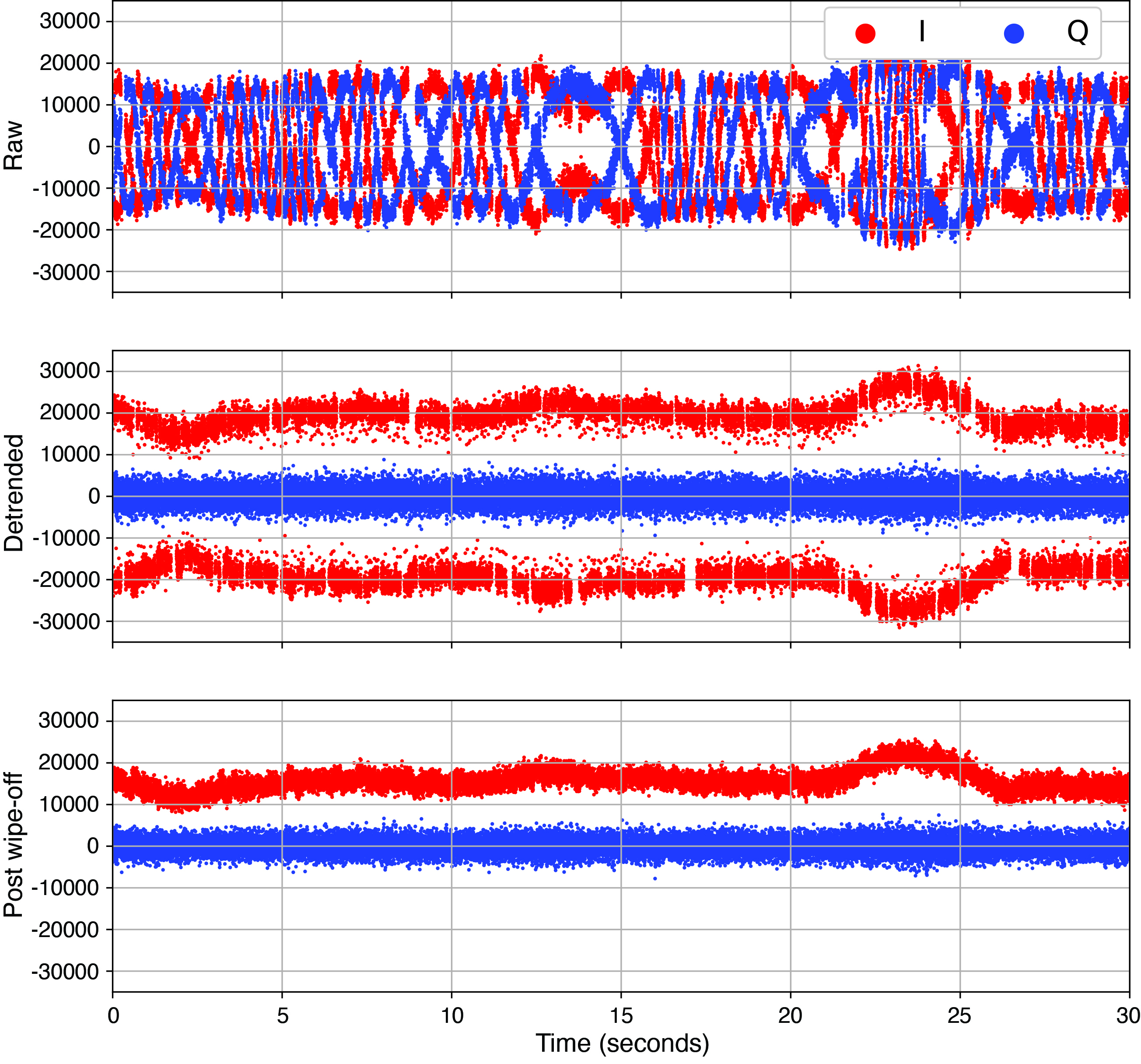
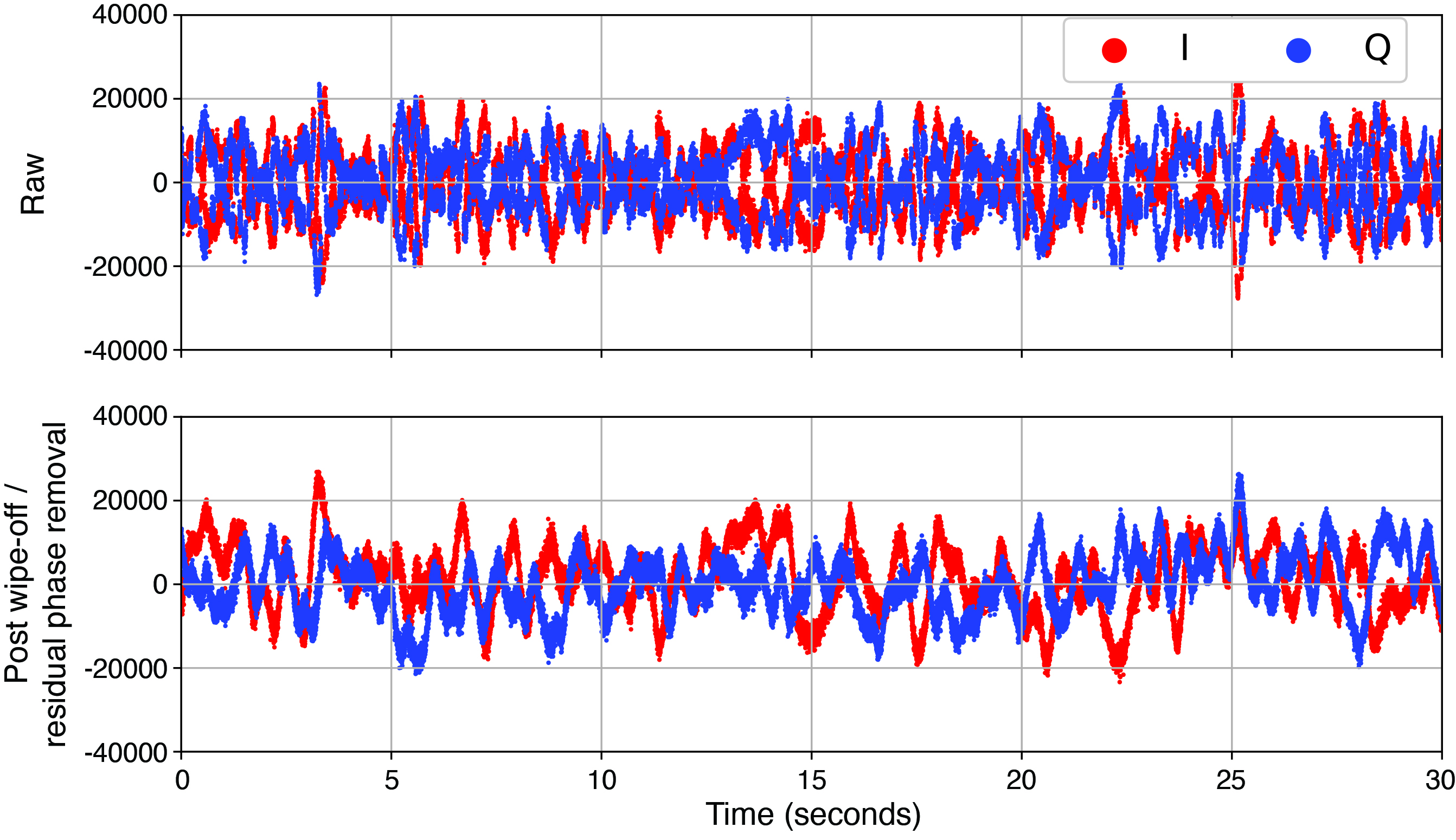
Carrier-Phase Processing. Once the correlations are performed, we take the I/Q correlations for both direct and reflected signals and process them to retrieve the cleaned reflected signal phase. The first series of steps in this process involve processing the direct signal to determine navigation / overlay symbol alignment and to estimate any residual phase fluctuations, which are mostly due to unmodeled receiver clock fluctuations. FIGURE 4 illustrates this process for the L1CA signal. The raw I/Q correlations are shown in the top panel. To these we apply a Costas phase-lock loop (PLL) to track the residual phase fluctuations without being sensitive to navigation / overlay symbol transitions. Next, we remove these residual phase fluctuations to obtain the detrended I/Q values.
Figure 4: The I/Q data cleaning process for the L1CA direct signal.
As shown in the second panel, these quadrature components of the detrended I/Q values are centered at zero while the in-phase component now shows the data bits / overlay symbols. We use the detrended I/Q values to estimate the navigation bit sequence on the L1CA and L2C signals. Likewise, we estimate the alignment of the Neumann-Hoffmann overlay sequence for the L5 signal. Finally, we wipe off the estimated data bits or overlay sequence to verify the procedure. The results of wiping off the estimated navigation bits for the L1CA signal are shown in the third panel of Figure 4.
Having obtained the residual phase fluctuations and navigation / overlay symbols for the direct signal, we next apply these to clean up the reflected signal. Specifically, we remove residual phase fluctuations from the raw reflected signal I/Q values and then wipe off the corresponding navigation bits or overlay code. FIGURE 5 shows an example of the reflected I/Q data before and after this procedure. The navigation bits are clearly removed, but the reflected signal still shows fairly significant fluctuations in the cleaned I/Q values. It is from these values that we hope to extract the residual reflected signal phase.
Figure 5: The reflected signal raw I/Q (top) and the I/Q after detrending and wiping off navigation bits for the L1CA signal.
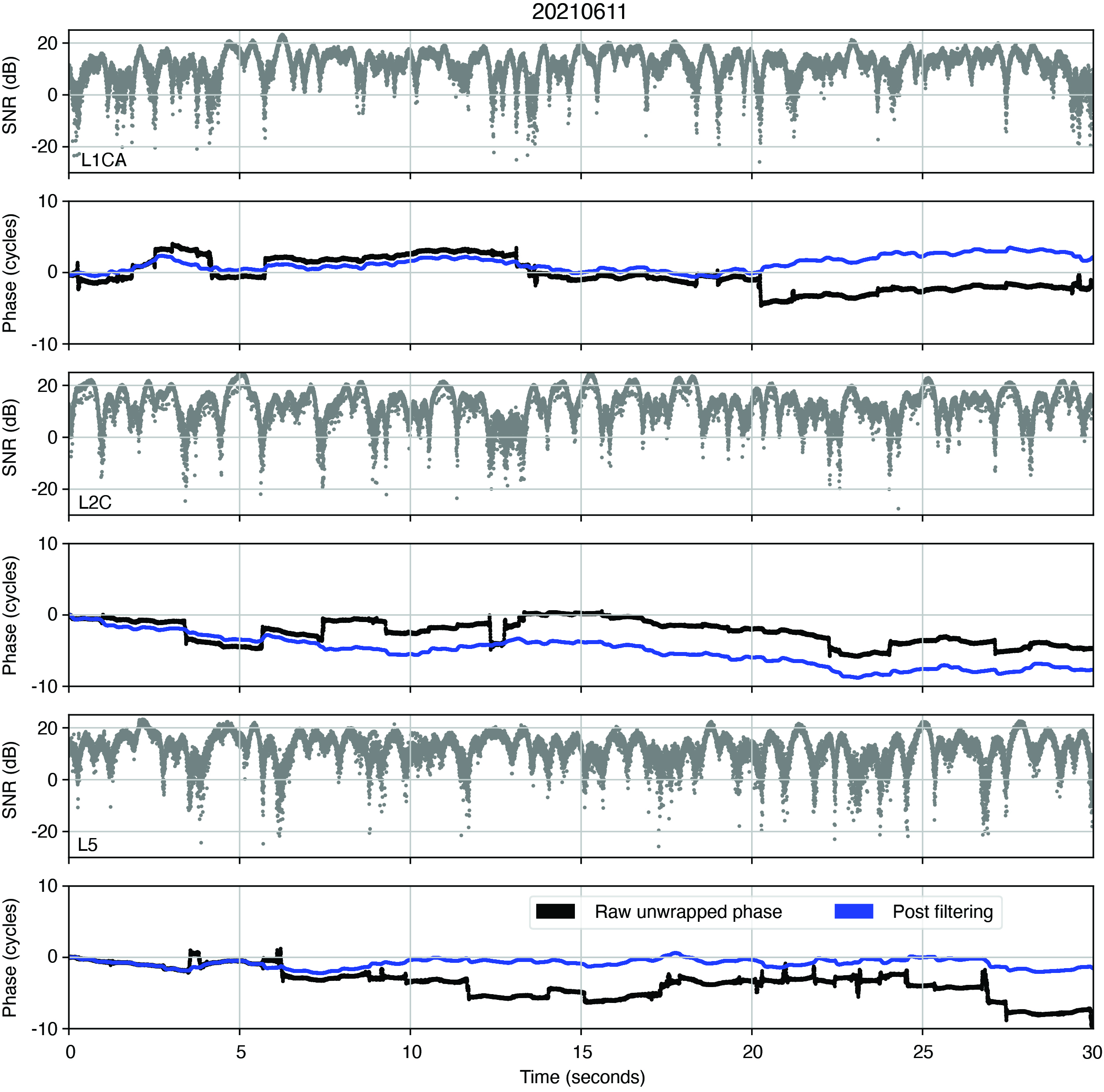
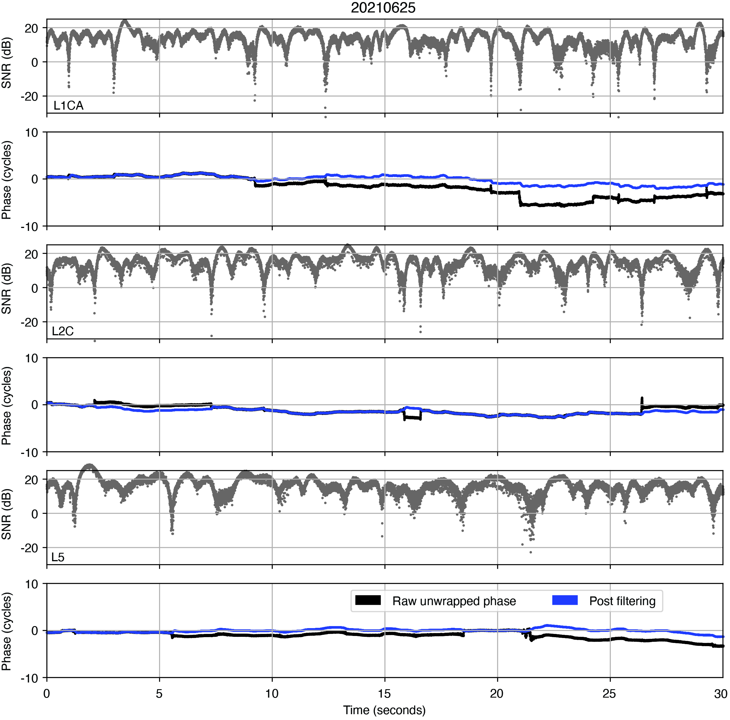
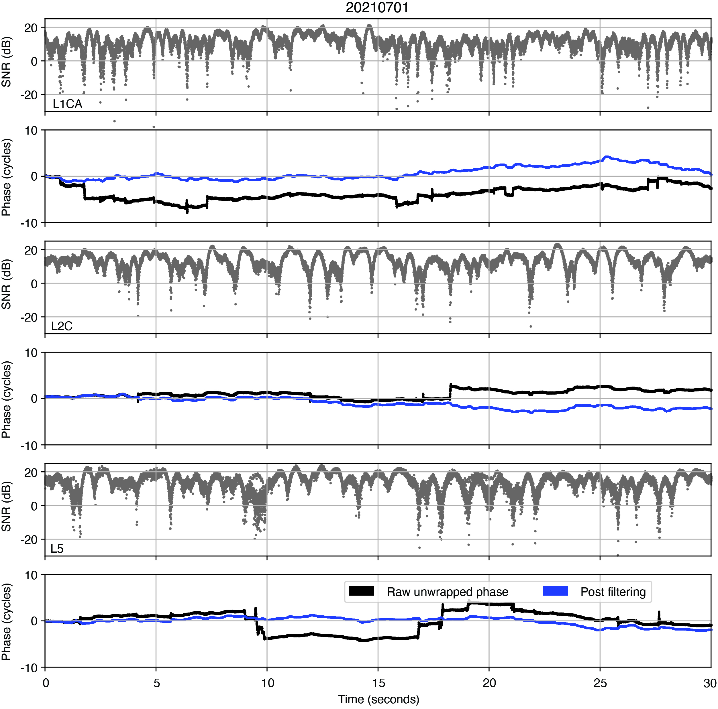
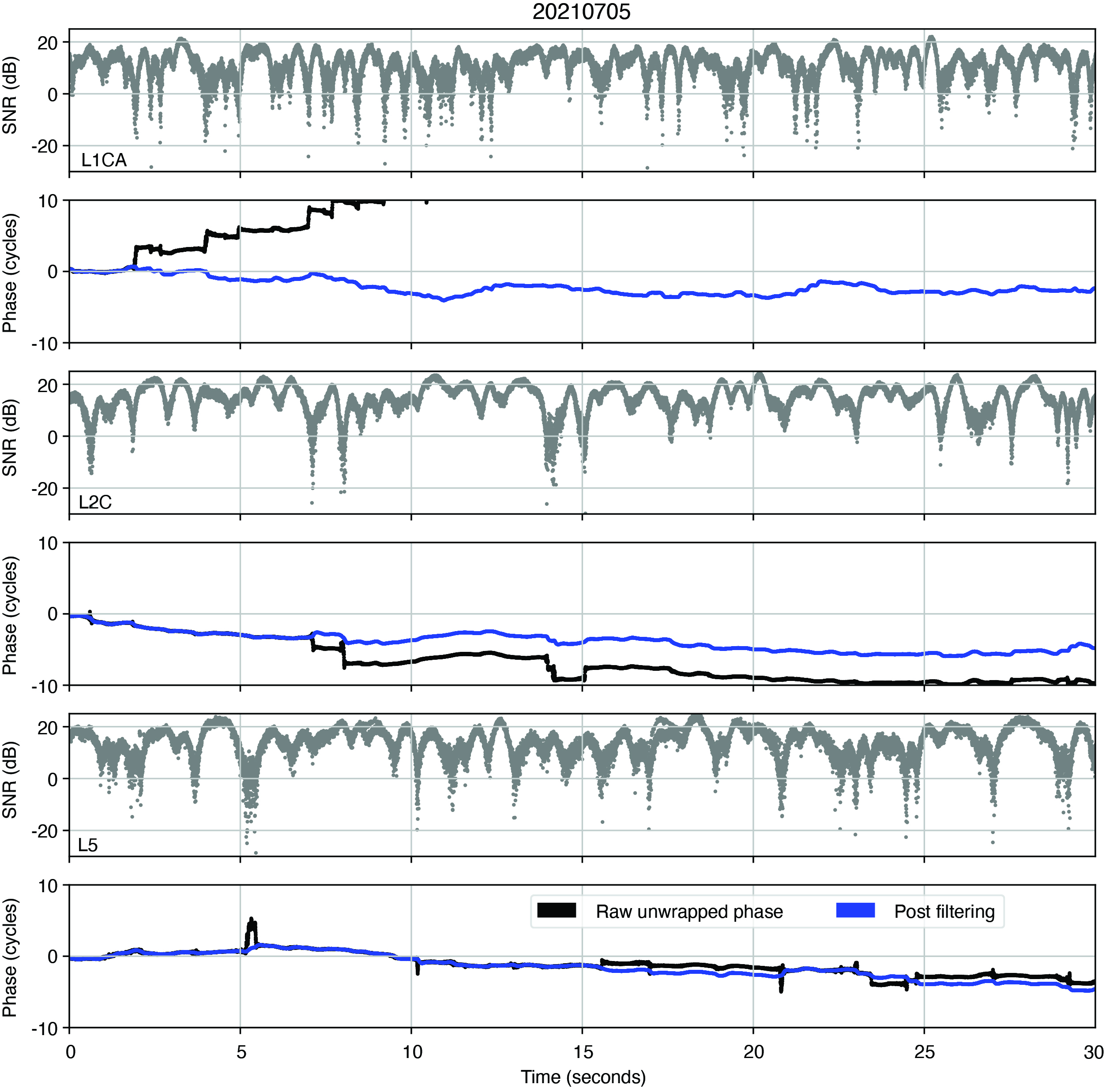
Under coherent conditions, the phase of the clean reflected I/Q data should contain only the unmodeled effects, including any signature of ocean surface height variation. However, the effect of multipath due to the rough ocean surface causes fluctuations in the received signal amplitude and phase, and can additionally cause cycle slips when we unwrap the phase. To filter out these cycle slips, we apply our simultaneous cycle slip and noise filtering (SCANF) method, which is essentially just a Kalman filter PLL with an additional step that tries to estimate and remove cycle slips. The figures in the next section show the results of applying this entire procedure to the reflected signals. The black and blue lines show the phase before and after applying SCANF. The reflected signal I/Q SNR is also included for reference. Note how the jumps in the black line coincide with SNR fades, and the blue line effectively recreates the phase trend of the black line without these jumps. This is good qualitative evidence that the SCANF algorithm was effective.
RESULTS
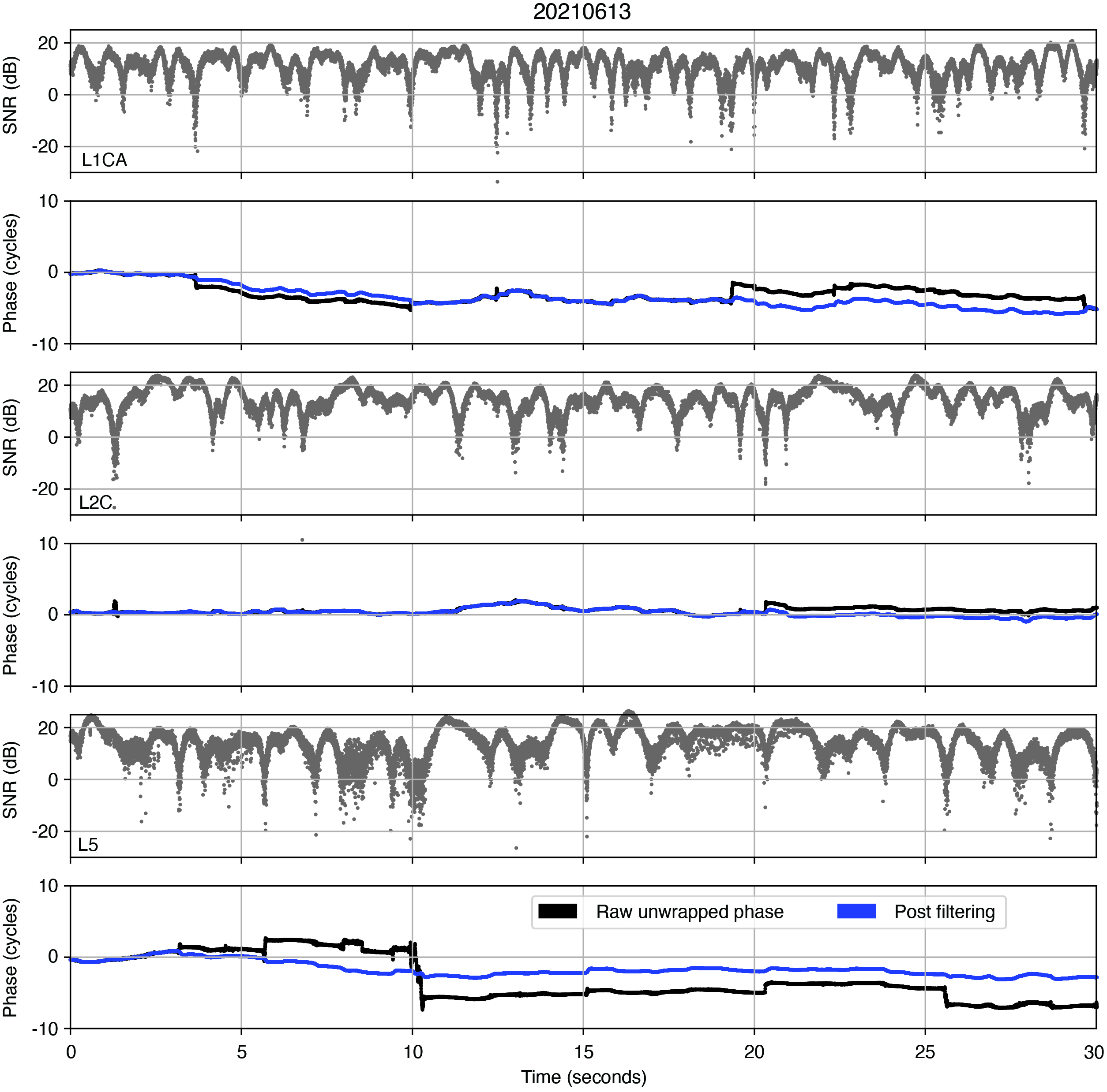
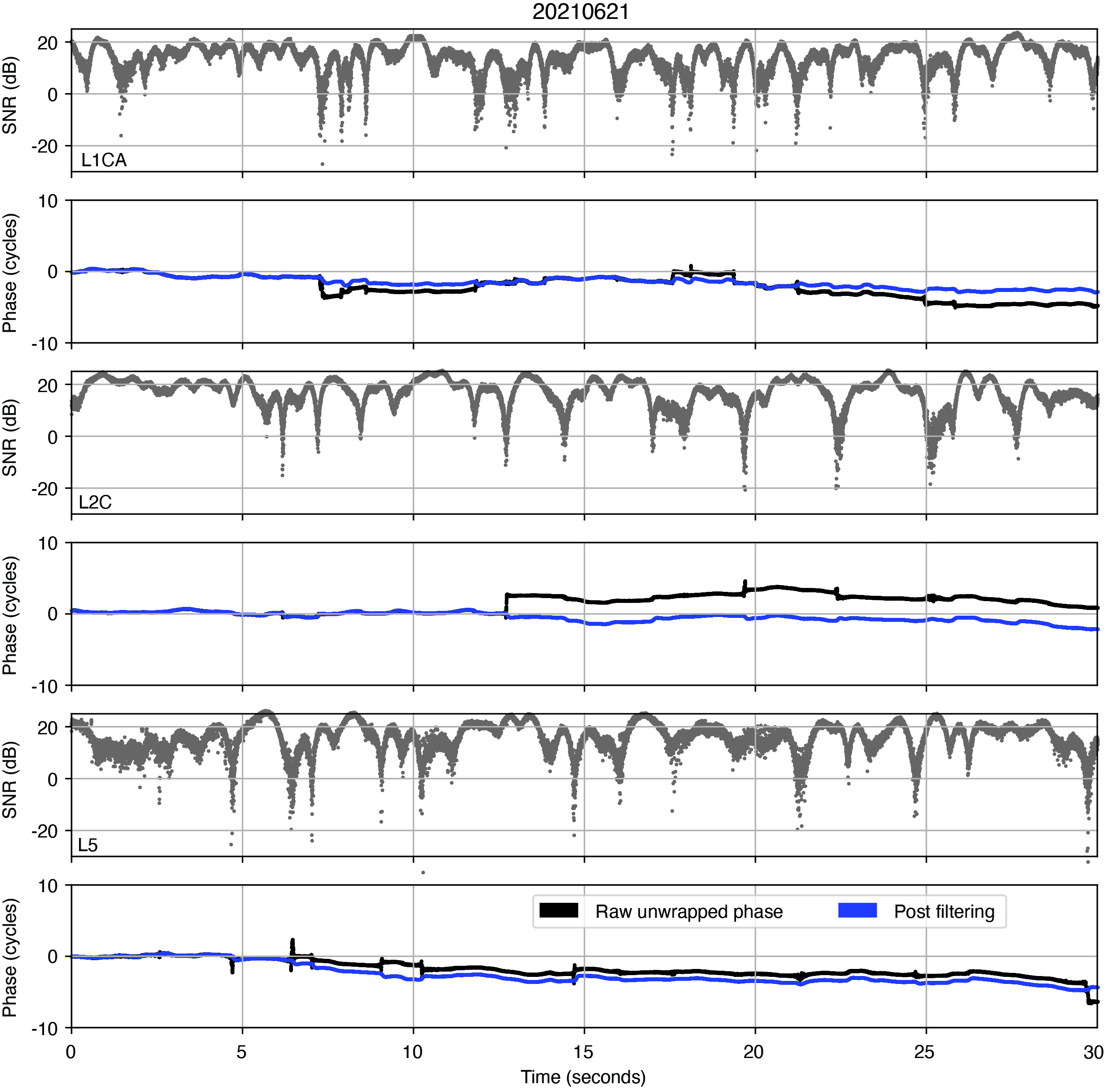
FIGURES 6, 7, 8, 9, 10, and 11 show the reflected signal SNR and phase for GPS PRN 6 on 6 different days. Note that these days correspond to the marked days in Figure 2, from which we observe that the wind-significant wave height is relatively high on days 1, 5, and 6, moderate on days 2 and 3, and relatively low on day 4. We noticed that the SNR fluctuations on days 1, 5, and 6 are comparatively more frequent than on other days, which we believe may be a signature of the ocean surface conditions. A more detailed analysis of this result is a topic for our future work.
Figure 6: Reflected signal residual phase before (blue) and after (black) applying the SCANF filtering for the June 11, 2021 dataset. Amplitude and phase are shown in alternating panels for L1CA, L2C and L5 respectively.Figure 7: Phase processing results for June 13, 2021.
Overall, we observe that the phase trend is not consistent across the three signals (L1CA, L2C, L5) for any of the days. With all the multipath signatures in the cleaned reflected signal, it was uncertain whether the extracted phase will be useful for applications such as ocean surface altimetry, and these qualitative results suggest that they probably will not be. However, season and hours of the day that were processed for our work discussed in this article are very limited. It is possible that processing more data will shed further insight onto whether the reflected signal phase is usable in this experiment.
Figure 8 Phase processing results for June 21, 2021.Figure 9: Phase processing results for June 25, 2021.
ACKNOWLEDGMENTS
The Haleakalā data collection system has been established with support from the University of Hawaii Institute of Astronomy, and the Air Force Research Laboratory. The authors appreciate the assistance from Michael Maberry, Rob Ratkowski, Daniel O’Gara, Craig Foreman, Frank van Graas and Neeraj Pujara. This research is funded by a subaward from the National Oceanic and Atmospheric Administration through the University Corporation for Atmospheric Research to CU Boulder and with partial funding support from the NASA Commercial Smallsat Data Acquisition program.
This article is based on the paper “Initial Carrier Phase Processing for the Haleakala Mountaintop GNSS-R Experiment” presented at ION ITM 2023, the 2023 International Technical Meeting of the Institute of Navigation, Long Beach, California, Jan. 23–26, 2023.
Figure 10: Phase processing results for July 1, 2021.Figure 11: Phase processing results for July 5, 2021.
BRIAN BREITSCH is a postdoctoral fellow at the University of Colorado (CU) Boulder, where he received his Ph.D. in aerospace engineering sciences. JADE MORTON is a professor in the Ann and H.J. Smead Department of Aerospace Engineering Sciences and the director of the Colorado Center for Astrodynamics Research at CU Boulder.
I/NAV improvements for all Galileo Open Service users is a part of the new Galileo services portfolio. (Image: EUSPA)
In 2023, Galileo continues to provide the world’s most precise satellite navigation information, to more than four billion users worldwide. Galileo services have expanded with many new capabilities that are unique with respect to other GNSS.
EUSPA and ESA continue to enjoy an effective collaboration on the many development, deployment and evolution activities of the Galileo Program, each according to its responsibilities for service provision and system development with the European Commission acting as the program manager.
Stable service performance
The service delivery operations, and the maintenance of the operational systems, are managed by EUSPA, who supervises several contracts that carry-out the day-to-day activities from dedicated control and monitoring centers throughout Europe. The Galileo timing, navigation and SAR/Galileo services provided in 2023 have been delivered with excellent performances that continue to exceed the formal declarations for minimum performance levels (MPL), both in terms of absolute accuracy and overall service availability.
Expansion of service portfolio
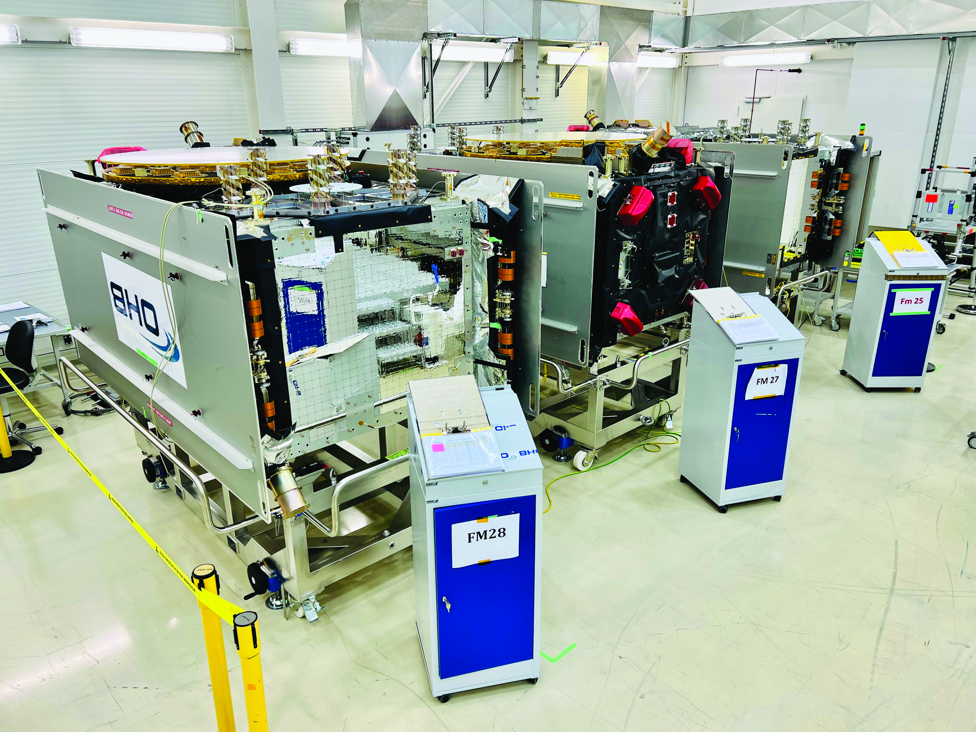
Galileo FOC batch three satellites in storage at OHB Systems. (Image: ESA)
The service provision teams have been able to focus on improvements to, and expansion of, the Galileo service portfolio.
OS and I/NAV improvement
Galileo Open Service (OS) users can already benefit from an improved navigation message, being broadcast by the Galileo constellation since mid-2023, which considerably boosts their performance in terms of robustness and time to first fix.
An update of the Galileo OS service definition document (SDD) is planned for the end of this year. This fourth issue of the OS SDD will bring to the users new MPLs (e.g., ranging rate accuracy and ranging accuracy at high percentiles) and improvements of existing MPLs, such as the timeliness of certain notice advisories to Galileo users. This updated OS SDD will also introduce the OS extended operation mode, which is characterized by a gradually degrading ranging accuracy with respect to the nominal operational mode, including outages of the Galileo ground segment, thus increasing the robustness of the OS.
High Accuracy Service
As of the HAS initial service declaration on January 24, Galileo became the first GNSS constellation ever to enable a decimetre-level accuracy, free of charge on a 24/7 basis over most parts of the globe in nominal conditions. The HAS corrections are transmitted directly via the Galileo signal in space (E6-B) and through the internet with the corresponding performance levels systematically met since the declaration. All documentation available here.
OS-NMA
The OS Navigation Message Authentication (OSNMA) will be a free and open access service allowing the users to confirm that received Galileo navigation data has not been modified and originates from the Galileo system, thus increasing the likelihood of detecting spoofing attacks at the data level and significantly contributing to the security of the solution. The OSNMA public observation phase is currently ongoing (gsc-europa.eu/support-to-developers/osnma-public-observation-test-phase). As part of that, the final OSNMA signal in space (SiS) interface control document (ICD) was published in December 2022, while the broadcast of a compliant SiS together with test certificates for the public key infrastructure started in August, marking the start of the OSNMA initial operational capability. The OSNMA initial service declaration will be achieved after the completion of the service validation activities and is targeted for early 2024.
Safety of life
The Galileo contribution to safety of life services (GoSoL) will cover the provision of Galileo signals and of service guarantees to enable the implementation of horizontal ARAIM service supporting aviation users. The service roadmap is currently under definition with a stepwise approach that will include the broadcast of a test ISM before the operational service is provided.
SAR
SAR/Galileo provides accurate, timely, and reliable distress alert data to help rescue authorities assist in distress situations (forward link service). It also acknowledges the receipt of the distress forward link alert to the beacon in distress via the Galileo navigation SiS (return link service). SAR/Galileo is a geographically distributed system, which was extended with a fourth European MEOLUT installed in La Reunion, in operation since November 2022.
The combination of SAR/Galileo space and ground assets provides excellent performance levels with a mean location accuracy of less than 800 m and a return link delivery latency of less than 1 min, which assisted in the rescue of approximately 1,400 people within EU territories in 2022.
Utilizing the return link service capabilities brings new innovations that further contribute to the global emergency space operations as Galileo moves forward to the implementation phase of the emergency warning satellite service (EWSS). The EWSS will provide national civil protection authorities with a satellite broadcasting capability to broadcast on-demand authenticated alerts to a precise target area and its population directly to any device capable of processing Galileo signals.
Reference documents for each of the above services can be found at the EUSPA European GNSS Service Center website, including technical notes, interface control documents and service declaration documents.
Image: European Space Agency (ESA)
Full operational capability infrastructure development toward completion
Space segment
The production of the third batch of Galileo FOC satellites, by the satellite manufacturer OHB Systems, has been completed for an overall amount of 12 satellites. The acceptance review for the last couple of spacecraft took place in June.
This amounts to an overall production by OHB Systems of 34 Galileo FOC Satellites (14 satellites in batch one, eight satellites in batch two and 12 satellites in batch three) of which 24 are in orbit. The remaining 10 satellites are in storage waiting for the next launch opportunity in 2024.
Ground segment
G2SB1 engineering model payload testing at ESA ESTEC. (Image: ESA)
The ground segment is going through a major upgrade with the roll-out of the new System Build 2.0 infrastructure in support of public regulated service IOC and open service FOC.
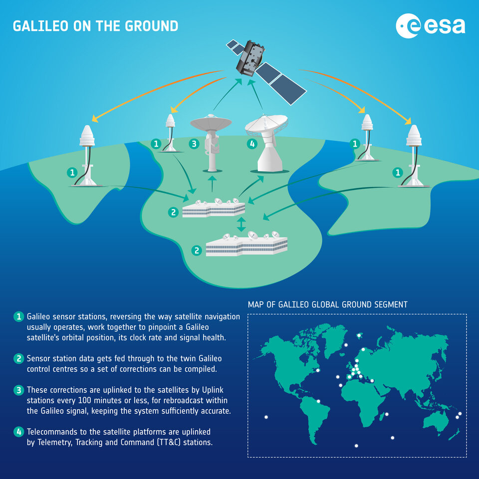
The new version of the ground mission segment developed by Thales Alenia Space France will be oriented to increase service robustness and resilience, besides high performance. It will provide virtualized hardware and software infrastructure at the Galileo Control Centers, triple receiver chain redundancy in the sensor stations’ remote sites and two additional sites located in Wallis (Pacific Ocean) and Bonaire (Caribbean Sea) to increase global coverage with 15 sites overall. A new mission monitoring capability has been implemented for the operators using the SAFE/Agile methodology. Furthermore, a system extended contingency mode will be implemented to cope with outages lasting up to seven days with smooth navigation performance degradation.
A new version of the Galileo Security Facility will be deployed at the Galileo Security Monitoring Centers offering an evolution of the public regulated service (PRS) capabilities through new enhanced SiS access control. Furthermore, a new state of the art cyber security monitoring system will be implemented.
The System Build 2.0 infrastructure qualification was completed by ESA in July. Migration in operation is based on an innovative concept consisting of a replica of the operational chains to ensure seamless transition from the current system in operation to the newly deployed one. The completion of the migration into operations is planned for the beginning of 2024, with the schedule being continuously monitored at the program level.
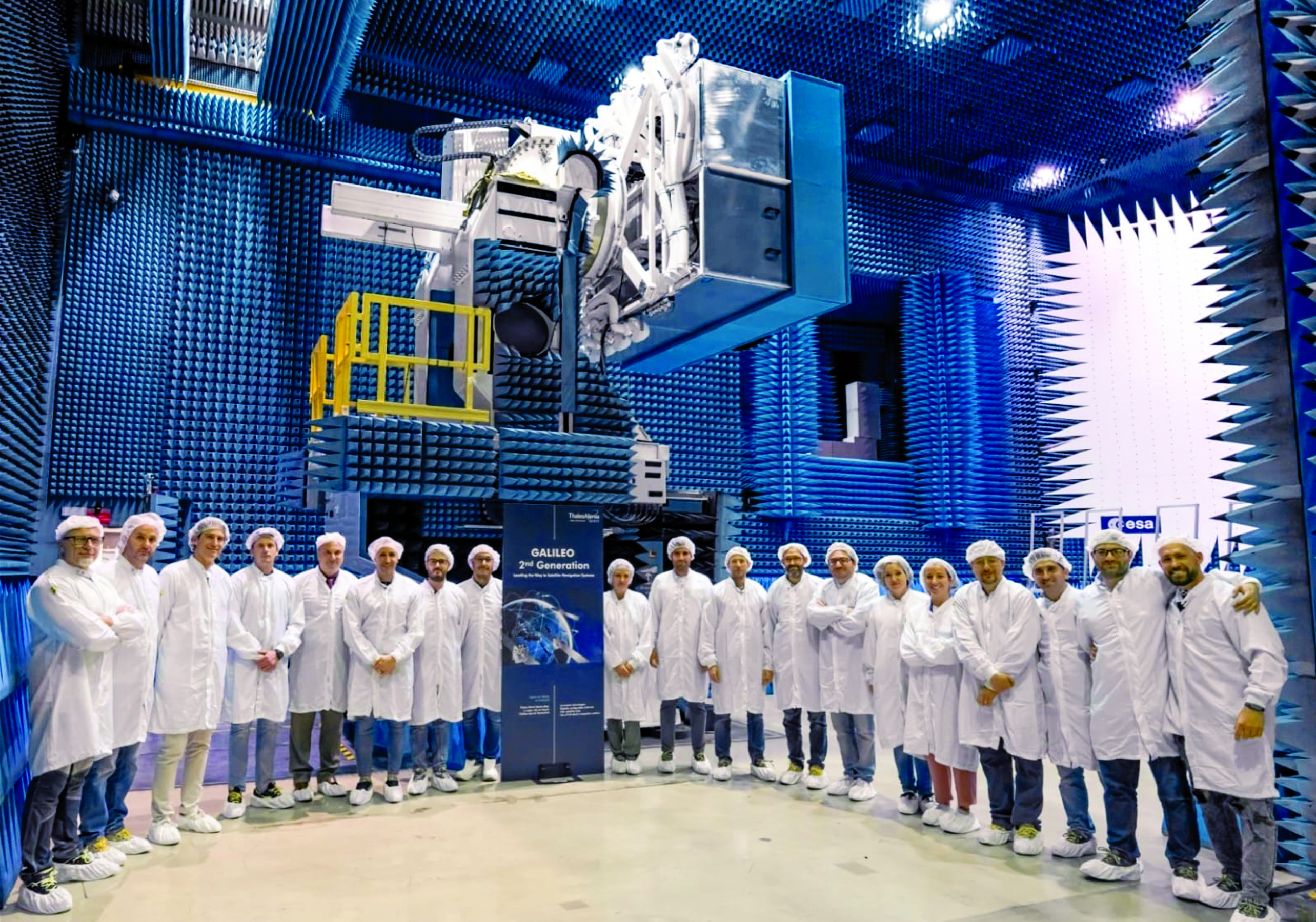
Galileo Second Generation: a constellation of state-of-the-art procurements. (Image: ESA)
An upgrade of the ground control segment in charge of command and control of the constellation is under qualification by the industrial consortium led by GMV. It will provide additional flexibility to allow for deployment in between launches and to address resolution of hardware and software obsolescence, including cyber security, operability improvements and a security monitoring overlay. Furthermore, it will upgrade the Telemetry Tracking and Control (TTC) station in Redu, Belgium, and deploy an additional station in Fucino, Italy, co-located with the Galileo Control Center, bringing to nine the overall number of TTC stations.
Second generation fast forward
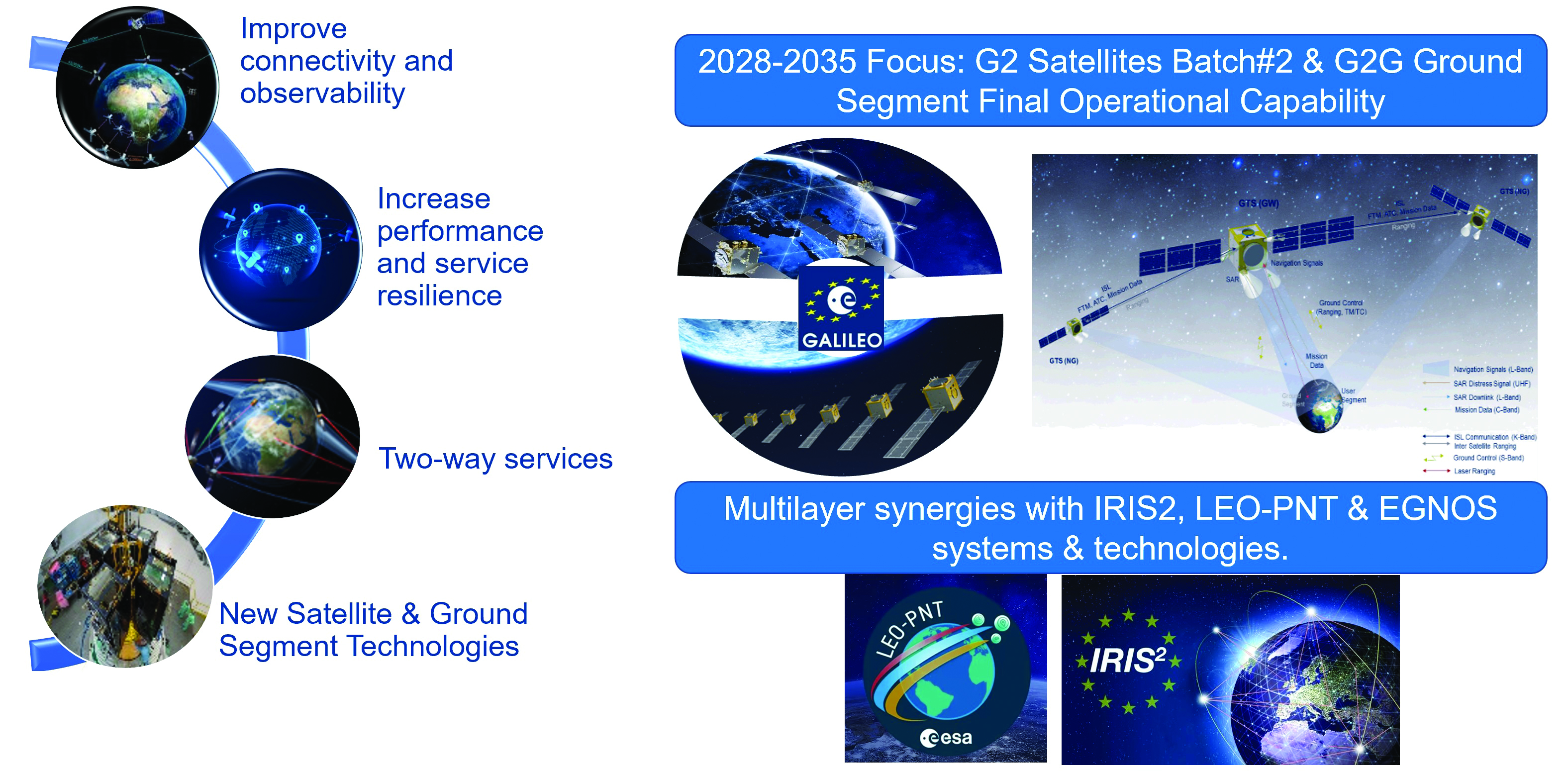
Galileo’s second generation (G2G) will introduce many innovative technologies to offer unprecedented precision, robustness, and flexibility.
For the development of G2G activities 2023 was a key year, with the development of the first batch of G2 satellites, the start of all contracts for in-orbit validation of the ground segment and system test beds and the preparation of the initial operational capability (IOC) design, through the consolidation of the mission/service roadmaps with the EC, EUSPA, and the delegates from EU member states.
This year, Europe has taken the necessary steps to unchain the development of key GNSS features, which will exponentially enhance GNSS accuracy for the worldwide communities in the future:
New and improved services.
Unique flexibility of ground and space systems to enable 12-18 months service time to market, without the need for constellation replenishment.
Upgraded robustness of key infrastructure items.
State of the art GNSS technology leading to centimeter-level precision.
New GNSS signals, including extended data capacity for added value services.
And of course, as a key factor, a full backward compatibility with Galileo First Generation and other GNSS systems.
G2G: Incremental steps for enhanced capabilities over the next decade
The ESA completed the G2G system preliminary design review in July, focused on three key incremental phases of the G2G:
G2G In-Orbit Validation (G2GIOV): specification, design and validation activities for the sake of ensuring the full development of the first batch of G2G satellites and all the associated infrastructure for launch and early orbit phase, in-orbit testing, in-orbit validation, initial enhancement of Galileo services and addition of new Galileo service components.
G2G Initial Operational Capability (G2GIOC): design and specifications required for the complementary procurements that will ensure new Galileo services, as enabled by G2G infrastructure, including both the second batch of G2G satellites and the G2G ground segment.
G2G Full Operational Capability (G2GFOC): Identification of key technological enablers and additional capabilities required for final G2G implementation, including the bridge to future synergies with other EU and ESA programs.
G2G in-orbit validation infrastructure – satellite hardware under validation
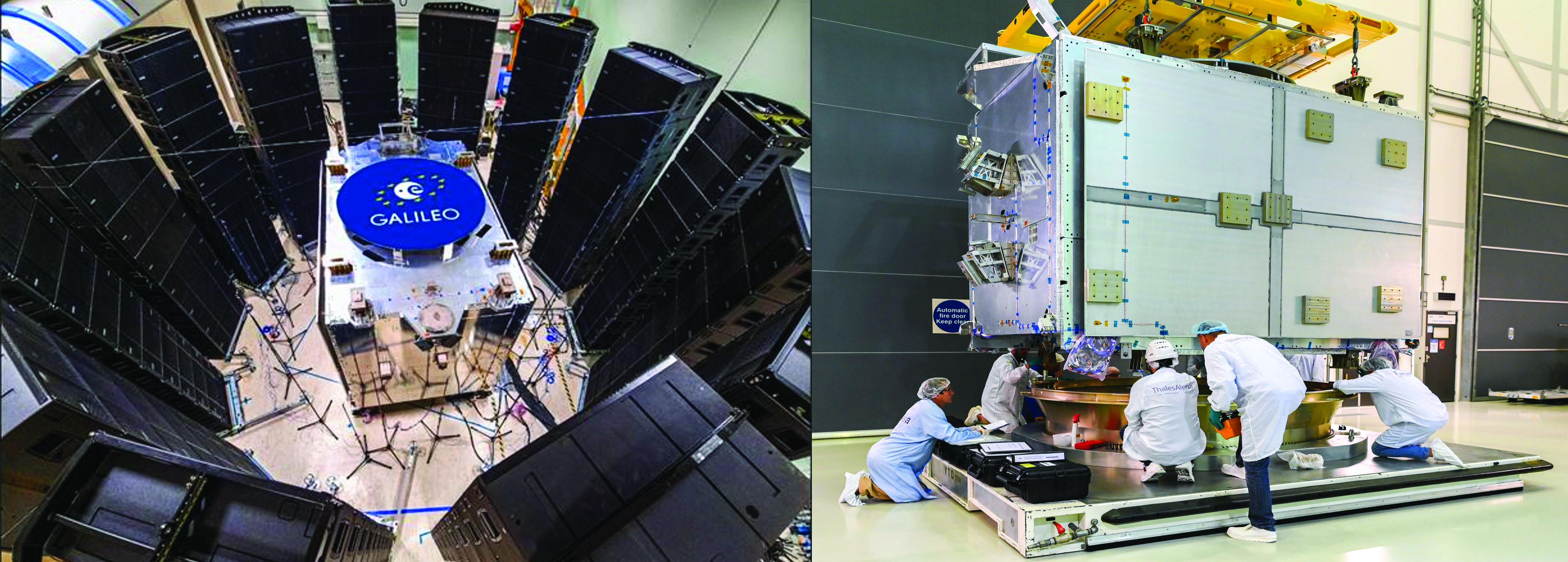
G2SB1 acoustic testing in Rome and structural model arrival at ESA ESTEC. (Image: ESA)
The two parallel contracts with Thales Alenia Space and Airbus to develop and manufacture each of six G2G batch one satellites (G2SB1A and B) achieved key milestones this year.
On the G2SB1 satellite A side, the prime contractor tested engineering model payloads and structural models at its premises and delivered them to ESA’s Technology Center (ESTEC). The validation of the new G2G payload capabilities and the key mechanical, vibration and acoustical testing milestones have been achieved.
These satellites will provide the following key innovations: reconfigurable fully digital navigation payload; point-to-point connection between satellites by inter-satellite-link for command and control, and ranging functionalities; electric propulsion for orbit-raising capabilities; advanced jamming and spoofing protection mechanisms; on-board authentication capabilities; increased ground-to-space data rate; and improved time reference (number of clocks and advanced clock monitoring functions).
Key mechanical and launch-related tests on the structural models stacked configurations were performed in the last quarter of this year, in order to simulate the launcher environment and satellite separation dynamics.
On the G2SB1 satellite B and the PHM and RAFS clock manufacturing sides, activities are ongoing as planned, with key HW infrastructure developed and tested in the respective Industrial Primes premises.
This included as key events in 2023 the full testing of the satellite advanced engineering model antenna and the creation of a satellite atomic clock farm in industry premises to produce the more than 70 atomic clocks required for the 12 G2 batch one satellites.
The next steps for these contracts are the completion of the equipment and satellite CDRs, expected in the coming months, in order to engage (starting at the end of 2024) with the critical system compatibility test campaigns of the G2G IOV ground segment infrastructure and system engineering test beds under development.
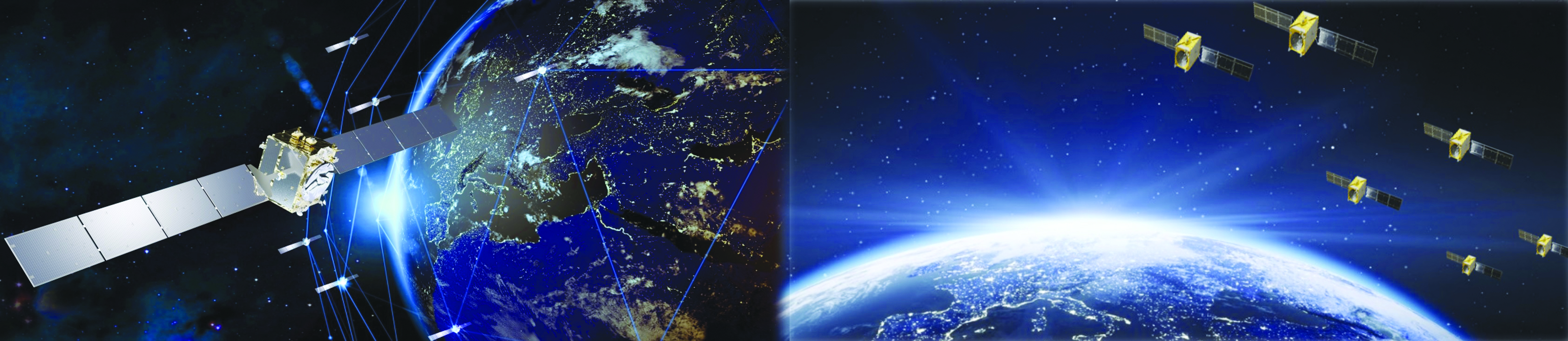
Galileo Second Generation batch one satellites. (Image: ESA)
G2G in-orbit validation infrastructure – ground segment and test beds in full development
The key system engineering, ground segment and test beds infrastructure procurements were all awarded during the first semester of 2023, giving EC/EUSPA/ESA and the industrial teams a brief moment of respite and celebration.
Following a competition process that encompassed about 12 months of detailed technical, management and legal interactions, 11 industrial prime contractors were selected for a set of contracts engaging about $1 billion euros of public sector investment:
Four contracts for system engineering, signal and performance, system validation and security and PRS activities.
Four contracts for ground segment in-orbit validation infrastructure.
Three contracts for system test bed activities plus a series of technological developments in the receivers and constellation simulation side.
Once completed in the years to come, these infrastructure developments will ensure not only the launch and early orbit phasing and in-orbit validation of the novel G2G satellite’s capabilities, but also enable the provision to all world users of enhanced Galileo services.
G2G satellites stacked configuration for launcher simulated test at ESA ESTEC. (Image: ESA)
G2G initial and final operational capability moving ahead
In line with the outcomes of the system preliminary design review, two new lines of GNSS improvements are well underway at program level.
In the area of G2G initial operational capability (IOC), which will provide new G2G initial services, an extensive preparatory work has been performed by EUSPA in order to derive the mission needs (as defined by the EC and its Member States), into a set of service evolution roadmaps for the more than one dozen Galileo services.
This work has been supported by ESA dossiers providing incremental implementation of these services, in a continuous improvement ramp-up process, which guarantees backward compatibility and seamless enhancement.
The relevant procurements that will enable, in combination with the in-orbit validation infrastructure, the provision of these services are currently under consolidation:
G2G IOC ground segment, with an initial version to be procured in 2024.
G2G satellites batch two, which is expected to start its competitive procurement procedure in the second part of the EU’s 2021-2028 multi-financial framework.
In addition, work is well advanced in the definition of the key technological developments and system trade-offs that will be analyzed for inclusion in the G2G final operational capability (FOC), expected early in the 2030s.
Critical technologies being analyzed include optical inter-satellite links, advanced governmental payloads, new ground segment and signal technologies and in-space constellation monitoring, among others. ESA expects to complete the preparation of the system-critical design review by the end of 2024 or early 2025 and to submit it for in-depth review by the EC, EUSPA and European member states stakeholders.
Conclusions
Galileo keeps providing continuous and stable services to users with new enhanced capabilities offering high accuracy, authentication and faster time to first fix. The space and ground infrastructure development for the first generation is progressing toward public regulated service IOC and open service FOC.
In parallel, for G2G, hardware production of the new satellites is well under way and the ground segment development has started to maintain Galileo competitive with the other GNSS.
We continue to strive toward achieving the vision defined at the end of the previous decade: “If you can imagine a novel satellite navigation service, we will implement it in 12-18 months.”
GNSS is like opium. Highly addictive, pleasing to the user, but laced with peril when you’re hooked. GPS World readers are well aware of the vulnerabilities, and probably aware of the serious concerns governmental bodies have about our reliance upon it. Here, we consider not so much how it can fail as what the impact of failure is on society, and what mitigations exist to minimize those impacts.
Impact on society
The most commonly cited causes of GNSS failure are jamming (unintentional and intentional) and spoofing. Less well appreciated are solar weather, satellite system errors, receiver system errors and, most importantly, cybersecurity-related errors. Any of these can cause a significant disruption to how society functions today.
The U.S. Department of Homeland Security identified that 15 out of the 18 Critical National Infrastructure sectors were vulnerable to GNSS failure: communications, emergency services, information technology, banking and finance, healthcare and public health, energy (electric, oil and gas), nuclear, dams, chemical, critical manufacturing, defense industrial base, postal and shipping, transportation, government facilities, and commercial facilities.
The threat is real and present. Conflicted areas are routinely jammed and spoofed. Even in peace, GNSS is fragile. In the past year, GNSS interference led to a runway at DFW airport being closed, a 33-hour GNSS outage in the Denver metro area, and even a recent Melbourne Formula One race had to be stopped for 40 minutes due to GNSS data problems.
Mitigations
In most cases, no alternate references are in place, and without them, it is difficult to know that the GNSS data being received is wrong. The ship Stena Impero, for example, was seized by Iran for being in its territorial waters. It is thought to have been victim to spoofing that led it there, but proving it is difficult.
Alternate references exist at low cost, but they generally divide “PNT” into “PN” and “T”, and whether on land, at sea or in the air. On land, most requirements are related to “T” because most applications, such as broadcast facilities and data centers, don’t move, and even when they do, there are enough landmarks available to at least make a sanity check. At sea and in the air, by contrast, motion is the reason we are there, there are few landmarks to confirm location, hence “PN” dominates.
For “T”, armageddon clocks can provide holdover for brief interruptions. However, they must be sufficiently tested to ensure that they succeed. In the Denver incident, radio systems had rubidium clocks for backup, but they drifted too far during the outage to be useable, whereas cellular networks, with alternate terrestrial timing sources, continued to work. Terrestrial time distribution systems over existing IP infrastructure, which Hoptroff supplies, work well globally, but are restricted to land-based time synchronization applications.
For “PN” and “T”, in air, sea and land, low-Earth orbit satellite services such as Satelles, Starlink and OneWeb provide global solutions. Their signals are much stronger than GNSS and therefore are much harder to jam or spoof, but they remain susceptible to interferences such as space weather, which destroyed 40 Starlink satellites on launch last year. However, as the Denver incident shows, until you test the solution, you never really know what might go wrong. eLoran terrestrial wireless solutions are very effective but limited in reach to within a few thousand miles of terrestrial transmitters. Such systems are being installed in South Korea and Saudi Arabia due to their proximity to hostile neighbors. They are likely to be installed in North America and Europe within the next decade.
What all these solutions have in common is that, while they are not expensive, they are not free, and are only available under license. Sovereign GNSS providers have, to date, provided PNT signals at no cost to the consumer. It must be accepted in the new landscape, not just that PNT is no longer free, but also that the supplier can choose its customers. Sovereign GNSS access could be restricted at the whim of a president. Private services are already selective — Starlink chose to provide the Ukraine with service during the current conflict, but it has no obligation to continue to do so.
Get on with the risk register
One of the biggest problems with preparing alternatives to GNSS is that the risk is ignored until it has started to have an impact on business and society. This can be addressed by ensuring that resilient PNT is on corporate and institutional risk registers. It is starting to happen now that governments have started to raise concerns. However, we have a way to go before inclusion on risk registers is a foregone conclusion.
This year marks 50 years since the U.S. Department of Defense approved the design for GPS and first funded the program. It is also the 30-year anniversary of an important milestone – initial operational capability of GPS. Please don’t let its longevity fool you into thinking it is past its prime! GPS is, and will remain, one of the most innovative systems ever designed, funded and operated by the U.S. government.
Today, GPS represents a highly successful public and private partnership, one in which diverse stakeholders continue to coordinate through fora such as the National Executive Committee for PNT and its Advisory Board. and the Civil GPS Service Interface Committee. How did this system become a military, public safety, critical infrastructure, and economic success? The world-class GPS community is made up of the teams and individuals who design, develop and operate these critical technologies as well as the people and organizations that benefit from its applications. From pioneers, scientists, engineers, and Guardians to civil servants, lawmakers, and entrepreneurs, the GPS community has transformed, is transforming, and will continue to transform lives across the globe, and soon, the moon.
GPS World highlighted the important roles played by many early GPS pioneers in a two-part series aptly titled, “Heroes” in the May and June 2010 issues. It has also covered Dr. Gladys West, who is one of the most consequential mathematicians and programmers to contribute to the global success of GPS. Her geodetic models helped refine our understanding of Earth’s shape, which proved fundamental to the success of GPS and its myriad applications. In 2021, the Trimble Foundation established the Dr. Gladys West Scholarship Program. Virginia State University (her alma mater!), North Carolina A&T State University, and Florida International University award four-year scholarships to one student per year to honor Dr. West’s achievements as a woman of science and a woman of color.
A celebration of GPS must also recognize our lawmakers — the people who authorize and appropriate funding for GPS and its augmentation programs. Nearly every U.S. federal department and agency uses these systems to fulfill their missions on behalf of the American people. They also leverage their technical, programmatic, operational, and experiential expertise to ensure that GPS and its augmentation systems remain the best in the world. This work is possible thanks to congressional committees, members of Congress, and staff. The Senate Appropriations and House Appropriations committees, the Senate Armed Services and House Armed Services committees, the Senate Commerce, Science and Transportation and the House Energy and Commerce committees, the GPS Caucus and many more members of Congress, provide critical oversight and funding. Their support ensures that GPS continues to bring $1.7 trillion and counting in economic benefits to the U.S. economy, creating hundreds of thousands of jobs while enhancing national security, public safety and critical infrastructure.
The future is bright for GPS manufacturers and those developing new applications. To realize their success, projects funded by the Infrastructure and Investment Jobs Act and the Inflation Reduction Act will depend on GPS to continue to deliver signals that are accurate, have integrity, and are available and continuous in nature. The next enterprising GPS entrepreneur is waiting in the wings
Thanks to a network of determined individuals, GPS-driven technologies — used to support precision agriculture, safe transportation, synchronized global banking, cutting-edge emergency response, elite and amateur sports, and more — are transforming our lives, creating jobs, and promoting growth across the economy.
GPSIA joins other members of the GPS community by celebrating 50 years of GPS and looks forward to the innovations and applications that will shape the next 50 years and beyond.
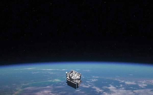
Clocks are at the heart of GPS. Advances in space-qualified atomic clocks that kept time to within 10 nanoseconds over a day were a key development that made GPS possible. It turns out that GPS must account for both special relativity and general relativity to deliver position at 1-meter level and time at 100-nanosecond level to its users. We’ll use these round numbers as user expectations from GPS.
In the simple engineering analysis below, we consider the problems that would have arisen if the engineers had ignored relativity in their design of GPS. The issues related to positioning and time transfer are distinct, so we treat them separately.
GPS is basically a bunch of synchronized, near-perfect clocks in orbit
It’s a mantra worth repeating: To measure ranges to GPS satellites with meter-level accuracy, the clocks on the satellites must keep time with nanosecond-level accuracy.
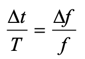
The clocks aboard GPS satellites are extraordinarily stable, typically to one part in 1013 over a day, which is another way saying that they could gain or lose on average 10-8 seconds, or 10 nanoseconds, over 105 seconds, which is roughly the length of a day. It’s a simple calculation. Suppose you measure a time interval of length with an oscillator advertised to have frequency f by counting its periods of oscillation. If the actual frequency is (f + Δf ), you’d measure the time interval as (T + Δt). It is easily shown that:
The fractional frequency stability (f / Δf ) is a key parameter. For an oscillator with stability (f / Δf ) of 10-13 over a day, as noted above, we can limit to 10 nanoseconds on average with data uploads to satellites once a day to re-sync the clocks. An error of 10 nano-seconds in time amounts to an error of about 3 meters in range computation and, speaking roughly, an error of about 3 meters in the position computed by the receiver. We can live with that.
Gravitational and motional effects on GPS clocks
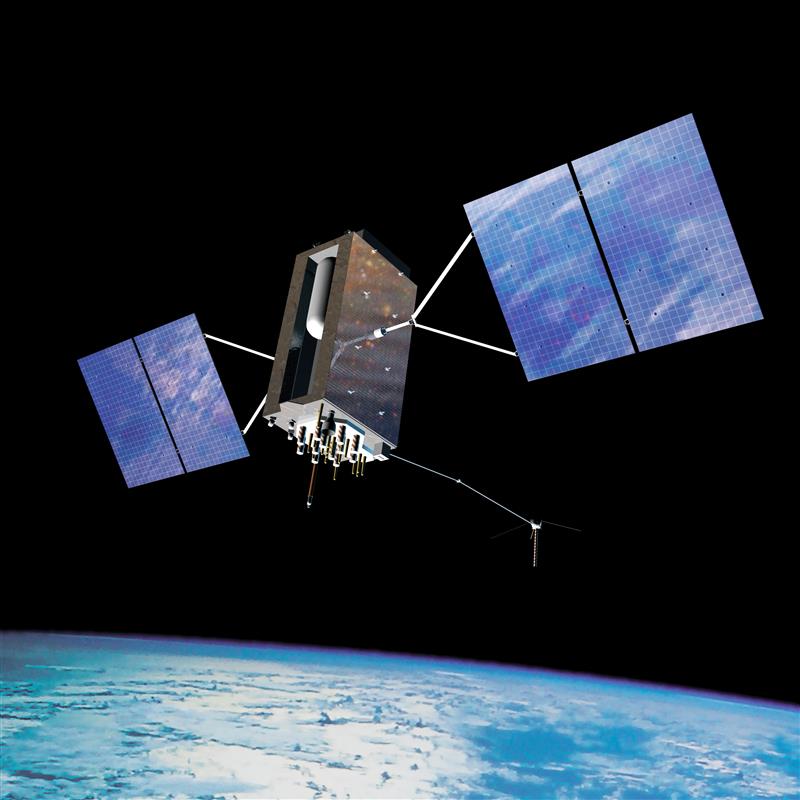
Our previous calculation of the timekeeping error of a satellite clock would have been fine had we not overlooked an important fact: We pretended as though the clocks were at rest on Earth at mean sea level. So, let’s see what relativity has to say about clocks in 20,000-kilometer-high circular orbits around Earth. The satellite orbits are not perfectly circular, or identical, but for now let’s pretend that they are. We call that modeling. The clocks would move at a rate of about 4 kilometers per second and exist in an environment where Earth’s gravity is only about one-fourth that at sea level.
According to the theory of special relativity, a moving clock ticks more slowly when compared with one that’s stationary at sea level. A clock aboard a GPS satellite will lose about 7 microseconds per day. That is three orders of magnitude larger than our budget for satellite clock error discussed earlier, therefore we can’t simply ignore it.
According to the theory of general relativity, on the other hand, a clock in a weaker gravitational field will tick faster than one that’s stationary at sea level. Apparently, gravity weighs down time, too. A clock aboard a GPS satellite in a medium Earth orbit will gain about 45 microseconds per day over a clock that’s at sea level on the earth.
The net effect: A GPS satellite clock will gain about 38 microseconds per day over a clock at rest at mean sea level. This effect is secular, meaning the time offset will grow from day to day.
So, you ask: Can you show me how you came up with these numbers, 7 micro-seconds and 45 microseconds? No, but I can point you to the references listed below and I can come close using simple mathematical models: (i) Earth’s gravitational potential is complicated and to simplify things we model Earth as homogeneous in composition and spherical in shape with a radius (rE) of 6,400 kilometers; (ii) aGPS satellite orbit is a circle with radius 4 rE; and (iii) the satellites move at the rate of 4 kilometers/second. We saved ourselves a lot of trouble by agreeing on this simple model.
sidebar
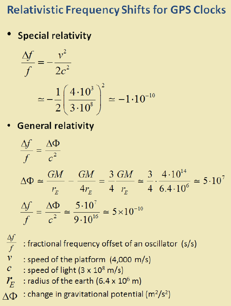
The calculation of the fractional frequency stability (f / Δf ) due to the relativistic effects is now easy and given in the sidebar. The answers are only approximate, but surprisingly close to the numbers cited above. That’s the beauty of good models. To calculate time gained or lost over a day, multiply by the length of a day in seconds.
As an interesting aside, note that the effects predicted by special relativity and general relativity cancel each other for clocks located at sea level anywhere on Earth. Consider two clocks, one located at the North or South Pole, and the other at the equator. The clock at the equator would tick slower because of its relative speed due to Earth’s spin, but faster because of its greater distance from Earth’s center of mass (about 22 kilometers) due to Earth’s flattening. Because Earth’s spin rate determines its shape, the two effects are not independent, and it’s no coincidence that they cancel exactly.
What if GPS forgot about relativity?
What would have happened if the engineers responsible for designing GPS had disregarded relativity? If the GPS satellites were in fact in identical, circular or-bits, their clocks would have shown a puzzling, but identical, behavior of gaining time over clocks of the Control Segment on Earth at a steady rate, about 38 microseconds over a day, the combined effect of special and general relativity.
What would that do to range measurements? A GPS receiver would have meas-ured the ranges to all satellites in view as too short by a common amount (up to about 11 kilometers between daily uploads of clock corrections). However, GPS receivers don’t measure ranges. To measure ranges, the receiver clock would have to be synchronized with the satellite clocks, an onerous requirement. The receivers use inexpensive clocks that drift and have frequency stability no bet-ter than . The receivers measure pseudoranges, i.e., ranges with a common bias on account of the receiver clock offset relative to GPS Time. This bias is es-timated by the receiver, along with its three-dimensional position. The price of an inexpensive receiver clock is that we now have four parameters to estimate and need pseudorange measurements from four satellites.
So, what would that do to positioning? The answer is that the common bias introduced by the relativistic effects would get lumped with the typically much larger bias introduced by the offset in the receiver clock. The position estimate would be unaffected.
Now, what about time from GPS? A GPS receiver used for timing is typically stationary with its antenna location carefully surveyed. In principle, a single pseu-dorange measurement can sync it to GPS Time (and UTC). So, if the relativistic effects had been ignored, the timing accuracy would have suffered to the ex-tent of 38 microseconds per day between updates of the clock parameters. That’s a deal-breaker, considering that we expect 100-nanosecond accuracy.
The relativistic effects discussed so far can be compensated for easily by setting the frequency of the satellite clocks lower (by 0.0045674 hertz) in what’s called “factory offset”: The frequency of a satellite clock is set to 10.22999999543 megahertz so that it will tick in orbit at the same rate as a 10.23-megahertz atomic standard at sea level on Earth. What an ingenious solution!
This factory offset would have accounted for the relativistic effects completely if the GPS satellite orbits were perfectly circular and identical. They are not. You can’t control an orbit perfectly.
So, what about eccentric orbits?
Yes, that’s a complication.
Each orbit is distinct and slightly elliptical. A consequence of this is that the sat-ellite speed is not constant (due to Kepler’s second law): the farther away a sat-ellite gets from Earth in its elliptical orbit, the slower it moves; and the farther away the satellite, the lower is the gravity field. That means the clocks in differ-ent satellites are speeding up and slowing down at different times and at differ-ent rates. The effect for each clock is periodic and quasi-sinusoidal. Averaging the effect over an orbit, we get zero.
For a satellite in an orbit with an eccentricity of 0.02, the net effect is that a clock can be ahead or behind by as much as 45 nanoseconds. The corresponding range error would amount to ± 15 meters. This effect must be accounted for specifically for each orbit. It would require serious bookkeeping on where the satellite has been in its elliptical orbit since the last data upload to sync its clock. It’s a messy business but can be simplified. We’d leave it at that. See ICD-GPS-200C, Section 20.3.3.3.3.1, if you want to see how it is implemented in your GPS receiver.
There is more to relativity than the special theory and general theory. There is the Sagnac effect associated with our rotating reference frames attached to Earth, in which we’d like to determine a position. The principle of constancy of the speed of light cannot be applied in a rotating reference frame, where the paths of the radio rays are not straight lines, but spirals. (Receivers at rest on Earth are moving quite rapidly: 465 meters per second at the equator.) There is also the Shapiro delay associated with the slowing of electromagnetic waves as they near Earth, which amounts to a fraction of a nanosecond. See the refer-ences for more on these topics.
Final thought: Could Einstein have imagined one hundred years ago that a bil-lion people would unknowingly account for the effects of his esoteric theory in their everyday activities?
Refrences
Ashby (1993), “Relativity and GPS,” Innovation column in GPS World
NVS-01 is the first second-generation satellite of the Indian Navigation Satellite System (IRNSS), also known as Navigation with Indian Constellation (NavIC). It was launched into geostationary orbit on May 20. The satellite is placed at 129.6° eastern longitude and will finally replace IRNSS-1G launched in April 2016.
Whereas the first-generation satellites transmit navigation signals in the L5- and S-band, NVS-01 is the first IRNSS satellite also transmitting in the L1-band. The 1547.42 MHz frequency is also used by other satellite navigation systems, including GPS, Galileo, and BeiDou-3. However, a different modulation is used, namely a Synthesized Binary Offset Carrier (SBOC) signal. The IRNSS L1 SBOC signal has data and pilot components with and without navigation data. Data and pilot signals consist of BOC (1,1) and BOC (6,1) components with sub-frequencies of 1.023 MHz and 6.138 MHz. A quadrature multiplexing is applied for the data and pilot components with a power sharing of 41.82% and 58.18%. The navigation message on the IRNSS L1 signal has a different structure compared to those on the legacy L5- and S-band signals. The new L1 navigation message uses an advanced frame structure and forward error correction inherited from the CNAV-2 message of the GPS/QZSS L1C signal as well as a similar orbit model. Among other things, it provides inter-signal corrections for the L1 data and pilot signals with reference to the S band signal for single-frequency L1 band users.
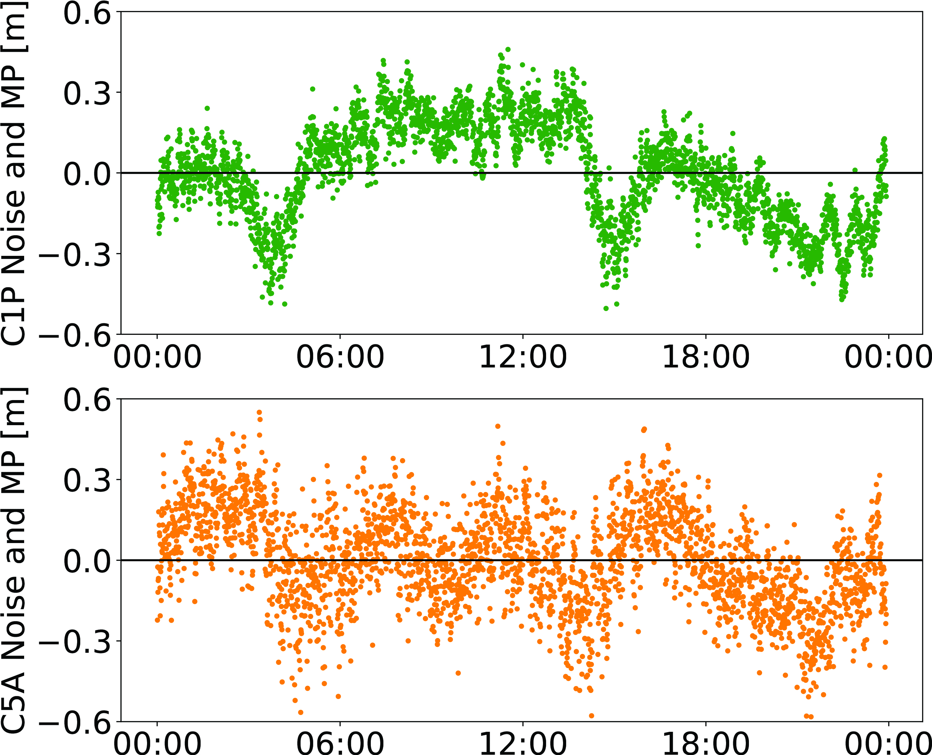
NVS-01 started signal transmission on June 17, 2023, with the pseudo-random noise (PRN) code I10. The satellite’s L1 and L5 signals were tracked by a Septentrio PolaRx5 receiver located in Tokyo, Japan, with a prototype firmware that is capable of tracking the L1 pilot signal. Figure 1 shows the multipath linear combination of NVS-01’s L1 and L5 pilot signals. Whereas the short-term variations are smaller for L1 compared to L5, the overall RMS is 18 cm for both signals.
Figure 1: Noise- and multipath linear combination for NVS-01’s L1 and L5 pilot signals received on 26 June 2023. (Image: All figures provided by the authors)
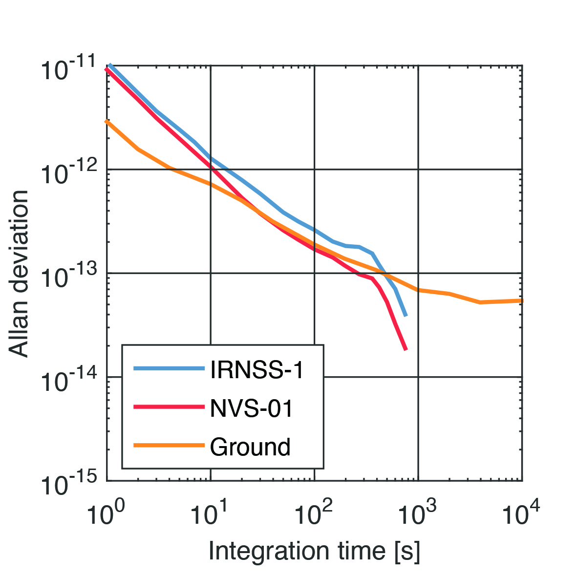
Whereas IRNSS-1’s rubidium clocks were provided by Spectratime, NVS-01 is the first satellite operating a new type of rubidium atomic frequency standard (RAFS) developed in India. The short-term performance of GNSS satellite clocks can be evaluated with the one-way carrier phase method. The receiver is connected to a highly stable external clock, e.g., a hydrogen maser. Thus, the receiver clock error is negligible. Measurement biases as well as the delays of ionosphere and troposphere on short time scales are removed by fitting a fourth-order polynomial. If no external clock is available, as is the case for the station in Tokyo, the precise clock information can be transferred from another station by a reference satellite jointly tracked by both receivers.
The Allan deviation based on this three-way carrier phase (TWCP) analysis is shown in Figure 2. The hydrogen maser of the IGS station USUD in Usuda, Japan, is used as the reference clock. At short integration times up to 20 s, the Allan deviation computed from the TWCP analysis is dominated by the GNSS measurement noise hiding the true clock performance. Above 20 s, the TWCP demonstrates that the NVS-01’s RAFS stability meets the performance of the ground tests and even exceeds them for longer integration times. At all integration times, the new RAFS outperforms the first generation IRNSS clocks.
Figure 2: IRNSS clock performance obtained from three-way carrier phase analysis as well as ground tests.
Manufacturers
GNSS data used in this article were collected with a Septentrio PolaRx5 receiver.
Peter Steigenberger and Oliver Montenbruck are scientists at the German Space Operations Center of the German Aerospace Center (DLR), where they conduct research in the field of new satellite navigation systems.
Jean‑Marie Sleewaegen is Lead Architect at Septentrio, Belgium, where he has been responsible for GNSS signal processing, system design and technology development since the company’s inception in 1999.
In May the President’s PNT Advisory Board heard a presentation about a National Guard project called NITRO. RNT Foundation President, Dana Goward, recently spoke with the project’s leader, Maj. Gen. Richard R. Neely, Adjutant General, Illinois National Guard, to find out more.
Mr. Goward: Thanks for speaking with us, General. Could you start by telling us what NITRO is and why it’s important?
Maj. Gen. Neely: Of course. NITRO is a project to ensure that the National Guard and our state’s first-responder partners can maintain communications and other critical functions even if we lose GPS timing signals.
NITRO is an acronym for Nationwide Integration of Timing Resiliency for Operations. ]You know how we in the military love our acronyms.
Telecoms and most of the rest of America’s critical infrastructure are dependent on timing from GPS. However, GPS signals are weak, highly vulnerable and under threat.
In addition to bad actors who can and do jam and spoof signals, accidental interference happens all the time. Operations at the Dallas and Denver airports were each interrupted by accident for more than a day last year, for example. A couple of years ago, a passenger airliner almost hit a mountain because of interference with GPS.
Q: It sounds like this is a safety of life issue.
A: It is. Right now, if we lost GPS signals and had to respond to a domestic attack, natural disaster, or other contingency, I am confident there would be additional unnecessary casualties. We are building NITRO so that we can save those lives and keep America safe.
Q: So how does NITRO work?
A: In addition to GPS, it gets multiple sources of space-based and terrestrial time from government and commercial providers. NITRO can use any trusted source. It is not provider- or vendor-specific.
Inputs are combined and compared, matched to the nation’s atomic clocks keeping Coordinated Universal Time, and users are sent the best accurate time multiple ways including over fiber, terrestrial broadcast, and resilient wireless networks.
Another great way in which I think it will be useful: NITRO gives us a common operating picture that can help detect and terminate GPS disruptions and anomalies around the country.
Q: Is the National Guard the only user?
A: Absolutely not! This is a state/federal partnership. The states’ Adjutant Generals are working with their Homeland Security Advisors to make it available to state, local, and tribal first responders. In some instances, also to critical infrastructure.
Even though we are in the early stages of implementation, NITRO is being used by seven states and 256 organizations and it is protecting more than 33 million people, including citizens here in Illinois.
Q: Is NITRO a tasking from the President or Congress? Who told you to do this?
A: NITRO helps execute long standing presidential policy and orders, as well as the recently released National Cybersecurity Implementation Plan. It also meets congressional mandates for backups and alternatives to GPS timing.
However, we created NITRO because we identified a serious threat to the National Guard’s mission execution. It closes 11 operational gaps for us, all without changes to end-user equipment.
Q: With what groups are the NITRO team working?
A: All the states are involved through their adjutant generals, homeland security advisors, and emergency managers. The NITRO board I chair is made up of the adjutant generals from six states.
We are also coordinating across the federal government, especially with the Departments of Homeland Security, Transportation, Commerce, and Energy.
As part of this we are partnering with the Department of Transportation to establish a NITRO engineering and operational site at Joint Base Cape Cod. This will allow engineers from different organizations to see more easily what we are doing and contribute their expertise.
Q: NITRO is going to provide timing signals in places and at times when GPS is not available. Won’t the National Guard also need navigation information?
A: Positioning and navigation are very important, but not quite as critical as timing. So, we are addressing that problem first. And since wireless location and navigation are often based on timing signals, NITRO will provide a good foundation for services and systems that can augment GPS-based navigation.
Q: So, how is the project going?
A: From a technical and operational standpoint, it’s going great. We have very high satisfaction ratings from NITRO users, and states are eager to be connected as soon as possible.
The technologies used are all mature, reasonably low cost, and most components are commercially available. So, engineering-wise it is low risk.
And our team is doing a great job helping folks move from full dependency on GPS to resilient positioning, navigation and timing (PNT) operations.
Q: Do you have any concerns going forward to full deployment?
A: The only thing I worry about is continued funding. Over the next five years we need something less than the cost of one GPS satellite. You would think that would be easy to find for an important effort like this, but it is a state/federal partnership, not a Department of Defense project. So, it falls into a kind of bureaucratic and budgetary no man’s land.
Q: What’s the solution for funding?
A: That’s not our call. The folks at the White House are exploring several alternatives, and I know several members of Congress are also concerned. We see a possibility of this fitting nicely with the recent infrastructure funding bill.
Q: It sounds like NITRO is something America really needs. Let’s hope they find a solution to the funding challenge, and quickly, to keep you on track. Thank you very much for your time!