GMV is leading the development of a secure two-way satellite time and frequency transfer system under the European Space Agency’s TOUCAN project.
The initiative safeguards critical infrastructure by reducing reliance on GNSS and enhancing national positioning, navigation and timing (PNT) capabilities. Funded by the UK Space Agency through its membership in ESA’s Navigation Innovation and Support Program (NAVISP), the project is an important part of the UK Government’s Framework for Greater PNT Resilience.
Through a competitive process, GMV was selected to enhance the UK’s national capabilities in delivering nationally assured, secure and continuous PNT services for critical infrastructure, defense and the broader economy.
TOUCAN, the two-way satellite time and frequency transfer capability demonstration (TWSTFT), will draw on GMV’s expertise in time transfer and system-level engineering, reinforcing the company’s role in supporting the government’s PNT resilience efforts.
“ TOUCAN represents a strategic milestone for GMV. It underscores our commitment to delivering cutting-edge, nationally assured, PNT solutions that are vital to the UK’s critical infrastructure and national security,” said Mark Dumville, general manager of GMV in the UK.
eLoran support
TOUCAN complements efforts to reestablish a UK eLoran system, which will serve as a terrestrial backup to satellite-based services. A critical goal is to ensure that this system operates independently of the more vulnerable GNSS.
The project’s primary objective is to establish an accurate, independently verifiable TWSTFT link between the eLoran transmitter and the National Physical Laboratory (NPL), the UK’s official timekeeping authority. The new link will address GNSS-dependence within eLoran, maintaining a time traceable to UTC (NPL).
In addition, the system will provide a TWSTFT connection to a facility that operates an R&D timescale, a secure reference that will one day be essential for synchronizing operations, maintaining communication integrity, and supporting mission-critical systems.
“Precise and secure timing is at the heart of so much we rely on every day, from banking and transport to energy and communications,” said Paul Bate, CEO of the UK Space Agency. “This investment in UK satellite timing through TOUCAN is about more than technology; it’s about protecting the everyday services people and businesses depend on. By working with GMV, the PNT Office and ESA’s NAVIS program, we’re helping to build a stronger, more resilient space ecosystem that safeguards our security and keeps the UK at the forefront of innovation.
GMV is delivering the design, integration and operational demonstration of the system, building on its proven track record in delivering secure national timing products and infrastructure. Project partner Viasat is supplying satellite bandwidth, as well as supporting GMV in analyzing innovative TWSTFT technology evolutions.
In January 2015, SpaceX publicly announced its plan to launch Starlink: a mega constellation of nearly 12,000 satellites in low-Earth orbit (LEO) to provide global broadband internet service. In May 2019, the first batch of 60 operational satellites were launched.
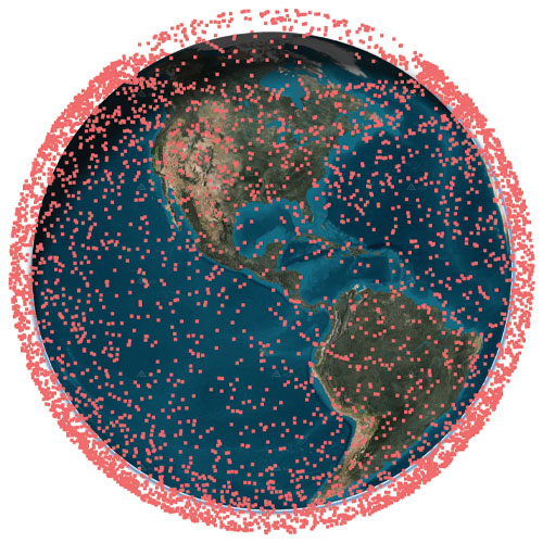
In October 2025, Starlink surpassed 10,000 satellites (see Figure 1). This remarkable achievement means that Starlink has more satellites than all other constellations have ever launched into LEO combined.
SpaceX is redefining global connectivity, delivering high-speed, low-latency internet anywhere on the planet1. Its civilian system, Starlink, is bridging the digital divide by providing reliable broadband in remote and underserved regions, enabling education, telemedicine and economic growth. Its defense and government variant, Starshield, is offering secure, resilient communications and rapid data transfer for military operations.
Figure 1 The current constellation of Starlink satellites in LEO, as of January 2026.
In the midst of the COVID pandemic, in a quiet campus building, the ASPIN Laboratory was busy researching Starlink’s mysterious proprietary signals and the satellites’ poorly known orbits. Having demonstrated the first experimental unmanned aerial vehicle (UAV)2 and ground vehicle3 navigation using Orbcomm LEO satellites, the team’s next grand objective was to exploit Starlink’s signals of opportunity for positioning, navigation, and timing (PNT). At the 2021 ION GNSS+ Conference, the team announced a new era of LEO PNT: the first successful exploitation of Starlink for PNT4. The team designed a cognitive software-defined receiver (SDR) capable of tracking the carrier phase 5 and Doppler6 of Starlink’s so-called pilot tones along with ephemerides error correction algorithms7. The SDR and algorithms were put into test to localize a stationary receiver. Starting from an initial estimate nearly 180 km away, listening to six Starlink satellites resulted in localizing the receiver to within 10 m. This led to worldwide research to study Starlink for PNT, from deciphering Starlink’s downlink orthogonal frequency-division multiplexing (OFDM) signals8,9, to analyzing its ephemerides and timing10,11, to studying the achievable PNT performance12,13.
This article presents the most advanced LEO PNT results to date with Starlink on four mobile platforms at geographically dispersed locations:
1. Ground vehicle in Pennsylvania
2. UAV in Ohio
3. Extremely high-altitude balloon in New Mexico
4. Maritime vessel in the Arctic near Greenland
Exploiting Starlink LEO for PNT: The enablers
SDR and signal analysis
Unlike GNSS, non-cooperative LEO satellites such as Starlink do not publicly disclose the structure of their downlink signals, so users must build their own “LEO PNTInterface Control Document (ICD)”14. This can be achieved via “reverse-engineering” the signal. A more powerful approach to “reverse-engineering” is via cognitive SDRs, which employ blind signal processing techniques to learn the signals on-the-fly, regardless of the adopted modulation and multiple-access scheme15.
The most comprehensive characterization to date of Starlink’s downlink signals for PNT was unveiled in16, utilizing the cognitive SDR approach, in which:
1. The full OFDM beacon was revealed.
2. Theoretical and experimental description for exploiting Starlink for PNT was provided, showing the maximum achievable carrier-to-noise density ratio (C/N0) under different scenarios: (i) pilot tones versus OFDM-based beacons and (ii) low-gain versus high-gain reception captures.
3. A Starlink LEO PNT SDR was designed, yielding the first successful extraction of navigation observables (carrier phase, Doppler shift and code phase) from Starlink’s OFDM signals.
4. A detailed analysis of the quality of Starlink navigation observables, including (i) signal activity and power levels and (ii) timing corrections that contaminate extracted observables along with mitigation strategies.
Ephemeris and timing error correction
Unlike GNSS, non-cooperative LEO satellites, such as Starlink, do not broadcast ephemeris and clock data, so users rely on public sources, such as two-line element (TLE) files. However, this data degrades over time due to orbital perturbations, limiting their effectiveness for PNT. Recent research addressed this challenge through five main approaches:
The next sections will showcase experimental LEO PNT results with Starlink signals of opportunity. All experiments utilized the SDR developed in16 and the ephemerides and timing correction methods developed in26-28.
Ground vehicle navigation in Pennsylvania
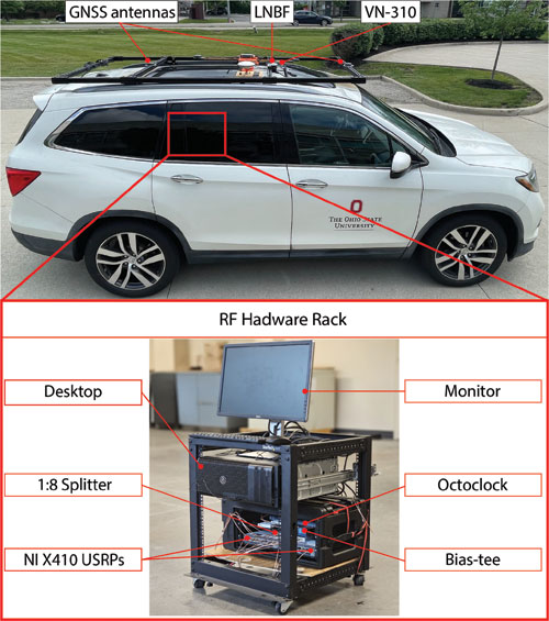
The experiment was conducted in June 2025. The ground vehicle navigated for 3 km in 120 seconds on Interstate 79 by Pittsburgh, Pennsylvania. GNSS signals were available for the first 30 seconds but were virtually cut off for the last 90 seconds, during which the vehicle traversed a 2.25 km trajectory. The vehicle was equipped with a VectorNav VN-310 dual GNSS/INS operating with real-time kinematic (RTK) corrections and a tactical-grade inertial measurement unit (IMU), from which the vehicle’s ground truth was generated. Starlink signals were captured over all eight Ku-band downlink channels using an upward low-noise block with feed-horn (LNBF) and processed at 2.5 MSps via two NI X410 USRPs.
Figure 2 shows the ground vehicle’s hardware setup. shows the ground vehicle’s hardware setup.
The vehicle navigated by fusing Doppler shift measurements from 11 Starlink satellites in a tightly-coupled fashion to aid the IMU, while altimeter measurements were fused in a loosely-coupled fashion. IMU updates were performed at a rate of 200 Hz. Starlink Doppler measurement updates were performed at a rate of 1 Hz with measurement noise variance inversely related to the received C/N0, ranging between 0.05 (m/s)2 and 6.5 (m/s)2, while altimeter updates were performed at a rate of 10 Hz with a measurement noise variance of 3 m2. The vehicle-mounted receiver and LEO satellites’ oscillator qualities were assumed to be that of an oven-controlled crystal oscillator (OCXO). A prior for the vehicle’s position and velocity was obtained from the on-board GNSS system. Starlink LEO satellites’ ephemeris errors were corrected via the equivalent timing error compensation technique in an online fashion as described in28. Each satellite’s equivalent timing error state was initialized with 0, while the relative clock drift state was initialized as the difference between the measured and predicted pseudorange rate.
An extended Kalman filter (EKF) was used to estimate the state vector, consisting of the vehicle’s orientation, 3D position, 3D velocity and the IMU’s 3D gyroscope and accelerometer biases along with the relative clock drift error between the receiver and each LEO satellite. The Starlink satellites’ orbits were generated by propagating TLE files with SGP4 for the duration of the experiment. The navigation solution was generated using three approaches:
1.Unaided IMU: The vehicle navigates via open-loop IMU measurements when GNSS measurements are unavailable.
2.LEO-aided IMU with TLE+SGP4 ephemerides: The vehicle fuses LEO measurements with IMU and altimeter measurements while incorporating TLE+SGP4 ephemerides in the navigation filter.
3.LEO-aided IMU with online ephemerides corrections: The vehicle fuses LEO measurements with IMU and altimeter measurements. Starting with TLE+SGP4 ephemerides, the navigation filter estimates an equivalent timing error for each satellite as described in28.
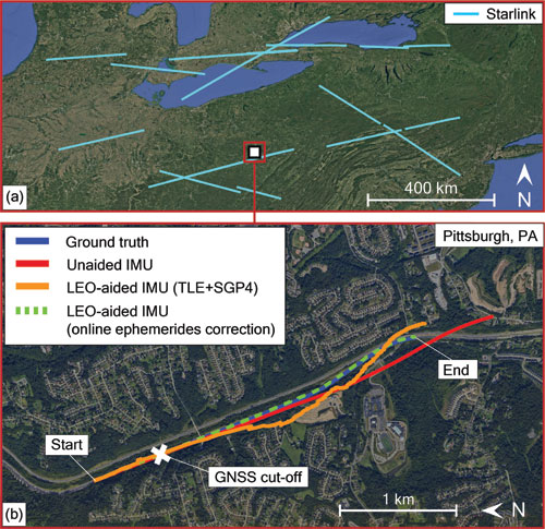
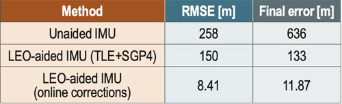
Figure 3 shows the Starlink satellite trajectories, as well as the vehicle’s ground truth and estimated trajectories with the three navigation approaches. The unaided IMU solution drifted to a 3D position root mean squared error (RMSE) of 258 m from the truth trajectory. The LEO-aided IMU solution that incorporated the erroneous TLE+SGP4 ephemerides resulted in a 3D position RMSE of 150 m, while the navigation solution employing the online ephemeris correction method resulted in an RMSE of 8.41 m.Table 1 summarizes the navigation results.
UAV navigation in Ohio
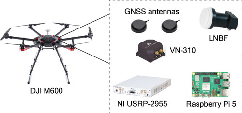
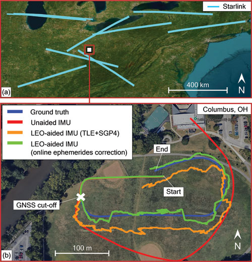
The experiment was conducted in August 2025. A DJI M600 UAV navigated for 500 m in 75 seconds in Columbus, Ohio. GNSS signals were available for the first 20 seconds of the experiment but were virtually cut off for the last 55 seconds, during which the UAV traversed a 370 m trajectory. The UAV was equipped with a VectorNav VN-310 dual GNSS/INS operating with RTK corrections and a tactical-grade IMU, from which the UAV’s ground truth was generated. Starlink signals were captured from the 4 low-side Ku-band channels using an upward LNBF and processed at 2.5 MSps via an NI 2955 USRP. Figure 4 shows the UAV’s hardware setup.
Figure 4 UAV’s hardware setup.
The UAV navigated by fusing Doppler shift measurements from nine Starlink satellites in a tightly-coupled fashion to aid the IMU, while altimeter measurements were fused in a loosely-coupled fashion. IMU updates were performed at a rate of 200 Hz. Starlink Doppler measurement updates were performed at a rate of 1 Hz with measurement noise variance inversely related to the received C/N0, ranging between 0.09 (m/s)2 and 6.75 (m/s)2, while altimeter updates were performed at a rate of 10 Hz with a measurement noise variance of 3 m2. The UAV-mounted receiver and LEO satellites’ oscillator qualities were assumed to be that of an OCXO. A prior for the UAV position and velocity was obtained from the UAV’s on-board GNSS system. Starlink LEO satellites’ ephemeris errors were corrected via the equivalent timing error compensation technique in an online fashion as described in 28. Each satellite’s equivalent timing error state was initialized with 0, while the relative clock drift state was initialized as the difference between the measured and predicted pseudorange rate.
An EKF was used to estimate the state vector, consisting of the UAV’s orientation, 3D position, 3D velocity and the IMU’s 3D gyroscope and accelerometer biases, along with the relative clock drift error between the receiver and each LEO satellite. The Starlink satellites’ orbits were generated by propagating TLE files with SGP4 for the duration of the experiment. The navigation solution was generated using the three approaches described in Section II.
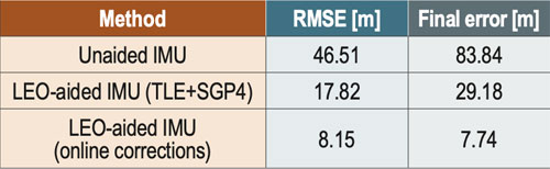
Figure 5 shows the Starlink satellite trajectories, as well as the UAV’s ground truth and estimated trajectories with the three different navigation approaches. The unaided IMU solution drifted to a 3D position RMSE of 46.51 m from the truth trajectory. The LEO-aided IMU solution that incorporated the erroneous TLE+SGP4 ephemerides resulted in a 3D position RMSE of 17.82 m, while the navigation solution employing the online ephemeris correction method resulted in an RMSE of 8.15 m. Table 2 summarizes the navigation results.
Figure 5 Experimental results of Doppler-based UAV navigation with Starlink: (a) trajectories of the nine Starlink satellites used to navigate the UAV and (b) UAV’s trajectory (blue) and estimated trajectories via the unaided IMU solution (red) and LEO-aided IMU solutions when incorporating the (i) uncorrected TLE+SGP4 ephemerides (orange) and (ii) online ephemeris correction (green).Table 2 Experimental results: UAV 3D position errors.
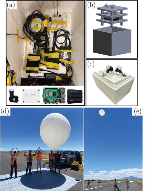
High-altitude balloon navigation in New Mexico
The experiment was conducted in July 202429. The balloon was launched from the Moriarty Municipal Airport in Moriarty, New Mexico, and landed just south of Mountainair, New Mexico, traveling a horizontal distance of about 105 km south with a 3D distance of about 119 km. The balloon reached a peak altitude of about 25.3 km (83,128 ft) above sea level. A specific time period was studied to evaluate utilization of Doppler observables for navigation at an elevation of 82,177 ft. During this period, five different Starlink satellites were tracked over a 50-second period, during which the balloon traveled 948 m. The balloon was equipped with a VectorNav VN-200 GNSS/INS, from which the ground truth trajectory was generated. Starlink signals were captured over two Ku-band downlink channels using an upward LNBF and processed at 2.5 MSps via two Ettus B205-mini USRPs. Figure 6 shows the balloon’s hardware setup.
Figure 6 (a)-(c) High-altitude balloon’s hardware setup. (d) OHIO in New Mexico, left to right: Jennifer Sanderson, Zak Kassas, Will Barrett and the Icarus Balloon. (e) Balloon launch.
The balloon navigated by fusing Doppler shift measurements from five Starlink satellites and altimeter measurements via an EKF. The dynamic model of the high-altitude balloon was chosen as a velocity random walk model, with acceleration process noise spectra set to 0.5 m2/s3 in the in the East, North and 0.8 m2/s3 in the in Up directions, respectively. Starlink Doppler measurement updates were performed at a rate of 10 Hz with measurement noise variance inversely related to the received C/N0, ranging between 1.40 (m/s)2 and 7.01 (m/s)2, while altimeter updates were performed at rate of 10 Hz with a measurement noise variance of 1 m2. The process noise covariance for the clock states was constructed according to an OCXO clock quality. A prior for the balloon’s position and velocity was obtained from the on-board GNSS system. Ephemeris data for each satellite was obtained from offline SGP4-propagated TLE, with epoch time corrections made by minimizing the residuals between predicted Doppler and measured Doppler26,27.
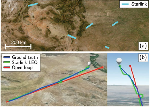
The EKF state vector consisted of the balloon’s 3D position and 3D velocity along with the relative clock drift error between the receiver and each LEO satellite. The navigation solution was generated using (i) an open-loop approach, which simply propagated the states via the dynamical model and (ii) the LEO+altimeter approach.
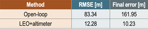
Figure 7 shows the balloon’s ground truth and estimated trajectories with the two different navigation approaches. The open-loop solution drifted to a 3D position RMSE of 83.34 m from the truth trajectory, while the LEO-aided solution resulted in an RMSE of 12.28 m. Table 3 summarizes the navigation results.
Figure 7 Experimental results of Doppler-based high-altitude balloon navigation with Starlink: (a) trajectories of five Starlink satellites used and (b) balloon’s trajectory (blue) and estimated trajectories via the open-loop solution (red) and LEO-aided solution (green).Table 3 Experimental results: High-altitude ballon 3D position errors.
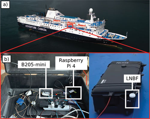
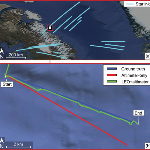
Maritime navigation in the Arctic
The experiment was conducted in August 202430. The vessel navigated for 8.5 km in 20 minutes off the shore of Baffin Island, Nunavut, Canada. Starlink signals were captured over the third Ku-band downlink channel using an upward LNBF and processed at 2.5 MSps via a B205-mini USRP and a Raspberry Pi 4. Figure 8 shows the vessel’s hardware setup.
Figure 8 Vessel’s hardware setup.
The vessel navigated by fusing Doppler shift measurements from 12 Starlink satellites and altimeter data via an EKF. The dynamic model of the vessel was chosen as a velocity random walk model. Starlink Doppler measurement and altimeter data updates were both performed at a rate of 10 Hz with measurement noise variances of 4.5 (m/s)2 and 3 m2, respectively. The vessel-mounted receiver and the LEO satellites’ oscillator qualities were assumed to be that of an OCXO. The vessel’s position states were initialized from the true position obtained from the on-board GNSS system. The velocity was initialized from the true velocity but with a 10˚ clockwise error with respect to the vessel’s direction-of-motion. The Starlink satellites’ orbits were generated by propagating TLE files with SGP4 for the duration of the experiment. Ephemeris errors were corrected by adjusting the TLE epoch time for eachsatellite26,27 to minimize the residuals between predicted Doppler and measured Doppler.
An EKF was used to estimate the state vector, consisting of the vessel’s 3D position, 3D velocity and the relative clock drift errors between the receiver and each LEO satellite. The navigation solution was generated via two approaches: (i) using only altimeter data and (ii) using LEO Doppler fused with altimeter data.
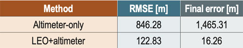
Figure 9 shows the Starlink satellite trajectories, as well as the vessel’s ground truth and estimated trajectories with the two navigation approaches. The altimeter-only solution drifted to a 3D position RMSE of 846 m from the truth trajectory. The LEO+altimeter solution resulted in a 3D position RMSE of 123 m. Table 4 summarizes the navigation results.
Figure 9 Experimental results of Doppler-based vessel navigation with Starlink: (a) trajectories of the 12 Starlink satellites used to navigate the vessel and (b) vessel’s true trajectory (blue) and estimated trajectories using (i) only an altimeter (red) and (ii) using LEO + altimeter (green).Table 4 Experimental results: Vessel 3D position errors.
Acknowledgments
This work was supported in part by the Office of Naval Research (ONR) under Grants N00014-22-1-2242 and N00014-22-1-2115, in part by the Air Force Office of Scientific Research (AFOSR) under Grant FA9550-22-1-0476, in part by the U.S. Department of Transportation under Grant 69A3552348327 for the CARMEN+ University Transportation Center, in part by The Aerospace Corporation under Award 4400000428, and in part by the Laboratory Directed Research and Development program at Sandia National Laboratories under award 2543953. Sandia National Laboratories is a multimission laboratory managed and operated by National Technology & Engineering Solutions of Sandia LLC, a wholly owned subsidiary of Honeywell International Inc., for the U.S. Department of Energy’s National Nuclear Security Administration under contract DENA0003525. This paper describes objective technical results and analysis. Any subjective views or opinions that might be expressed in the paper do not necessarily represent the views of the U.S. Department of Energy or the United States Government.
The authors would like to thank Vasilios Konstantacos, Jackson Morris, Ethan Shaw, Khaled Hamil, Aiden Short and Andrew Ye for constructing the balloon’s payload; Mark Andrews for supervising the payload design; and Prabodh Jhaveri, Danny Bowman, Mike Fleigle and Justin LaPierre for helping with launch and recovery of the balloon. The authors would also like to thank The Explorers Club and Adventure Canada for their help with data collection in the Arcitc. The authors would like to thank VectorNav for supplying the VN-200.
References
1. A. Yadav, M. Agarwal, S. Agarwal, and S. Verma, “Internet from space anywhere and anytime – Starlink,” in Proceedings of International Conference on Advancement in Electronics & Communication Engineering, pp. 1-8, 2022.
2. J. Morales, J. Khalife, A. Abdallah, C. Ardito, and Z. Kassas, “Inertial navigation system aiding with Orbcomm LEO satellite Doppler measurements,” in Proceedings of ION GNSS+ Conference, pp. 2718-2725, 2018.
3. Z. Kassas, J. Morales, and J. Khalife, “New-age satellite-based navigation – STAN: simultaneous tracking and navigation with LEO satellite signals,” Inside GNSS Magazine, (14)4, pp. 56-65, 2019.
4. M. Neinavaie, J. Khalife, and Z. Kassas, “Exploiting Starlink signals for navigation: first results,” in Proceedings of ION GNSS+ Conference, pp. 2766-2773, 2021.
5. J. Khalife, M. Neinavaie, and Z. Kassas, “The first carrier phase tracking and positioning results with Starlink LEO satellite signals,” IEEE Transactions on Aerospace and Electronic Systems, (58)2, pp. 1487-1491, 2022.
6. M. Neinavaie, J. Khalife, and Z. Kassas, “Acquisition, Doppler tracking, and positioning with Starlink LEO satellites: first results,” IEEE Transactions on Aerospace and Electronic Systems, (58)3, pp. 2606-2610, 2022.
7. Z. Kassas, M. Neinavaie, J. Khalife, N. Khairallah, S. Kozhaya, J. Haidar-Ahmad, and Z. Shadram, “Enter LEO on the GNSS stage: navigation with Starlink satellites,” Inside GNSS Magazine, (16)6, pp. 42-51, 2021.
8. T. Humphreys, P. Iannucci, Z. Komodromos, and A. Graff, “Signal structure of the Starlink Ku-band downlink,” IEEE Transactions on Aerospace and Electronic Systems, (59)5, pp. 6016-6030, 2023.
9.M. Neinavaie and Z. Kassas, “Cognitive sensing and navigation with unknown OFDM signals with application to terrestrial 5G and Starlink LEO satellites,” IEEE Journal on Selected Areas in Communications, (42)1, pp. 146-160, 2024.
10. S. Hayek and Z. Kassas, “Warm start navigation with non-cooperative LEO satellites via online ephemeris error estimation,” in Proceedings of IEEE/ION Position, Location, and Navigation Symposium, pp. 112-123, 2025.
11. W. Qin, A. Graff, Z. Clements, Z. Komodromos, and T. Humphreys, “Timing properties of the Starlink Ku-band downlink,” IEEE Transactions on Aerospace and Electronic Systems, (62), pp. 727-744, 2026.
12. H. More, E. Cianca, and M. De Sanctis, “Comparing positioning performance of LEO mega-constellations and GNSS in urban canyons,” IEEE Access, (12), pp. 24465-24482, 2024.
13. Z. Kassas and J. Saroufim, “LEO PNT frameworks for non-cooperative satellites with poorly known ephemerides: open-loop SGP4, tracking, and differential,” IEEE Aerospace and Electronic Systems Magazine, (40)1, pp. 46-71, 2025.
14. S. Kozhaya, H. Kanj, and Z. Kassas, “Multi-constellation blind beacon estimation, Doppler tracking, and opportunistic positioning with OneWeb, Starlink, Iridium NEXT, and Orbcomm LEO satellites,” in Proceedings of IEEE/ION Position, Location, and Navigation Symposium, pp. 1184-1195, 2023.
15. S. Kozhaya, S. Hayek, and Z. Kassas, “Cognitive beacon estimation of unknown LEO satellites signals of opportunity for PNT,” IEEE Journal on Selected Areas in Communications, pp. 1-16, 2026, in-press.
16. S. Kozhaya, J. Saroufim, and Z. Kassas, “Unveiling Starlink for PNT,” NAVIGATION, Journal of the Institute of Navigation, (72)1, pp. 1-35, 2026.
17. J. Khalife and Z. Kassas, “Performance-driven design of carrier phase differential navigation frameworks with megaconstellation LEO satellites,” IEEE Transactions on Aerospace and Electronic Systems, (59)3, pp. 2947–2966, 2023.
18. M. Hasan, M. Kabir, M. Islam, S. Han, and W. Shin, “A double difference Doppler shift-based positioning framework with ephemeris error correction of LEO satellites,” IEEE Systems Journal, (18)4, pp. 2157-2168, 2024.
19. Z. Kassas, S. Hayek, and J. Haidar-Ahmad, “LEO satellite orbit prediction via closed-loop machine learning with application to opportunistic navigation,” IEEE Aerospace and Electronic Systems Magazine, (40)1, pp. 34-49, 2024.
20. K. Selvan, A. Siemuri, F. Prol, P. Välisuo, and H. Kuusniemi, “Machine learning for LEO and MEO satellite Orbit prediction,” in Proceedings of ION GNSS+ Conference, pp. 3556 -3571, 2024.
21. J. Saroufim and Z. Kassas, “Ephemeris and timing error disambiguation enabling precise LEO PNT,” IEEE Transactions on Aerospace and Electronic Systems, (61)3, pp. 6138–6153, 2025.
22. J. Saroufim and Z. Kassas, “LEO ephemeris error modeling enabling long baseline correction for improved PNT,” in Proceedings of IEEE/ION Position, Location, and Navigation Symposium, pp. 625–630, 2025.
23. N. Khairallah and Z. Kassas, “Ephemeris tracking and error propagation analysis of LEO satellites with application to opportunistic navigation,” IEEE Transactions on Aerospace and Electronic Systems, (60)2, pp. 1242–1259, 2024.
24.S. Kozhaya, J. Saroufim, S. Hayek, P. El-Kouba, and Z. Kassas, “Light will guide you: passive joint DOA/FOA sensing, tracking, and navigation with unknown LEO satellites,” in Proceedings of IEEE/ION Position, Location, and Navigation Symposium, pp. 716–727, 2025.
25.Y. Du, H. Qin, and C. Zhao, “LEO satellites/INS integrated positioning framework considering orbit errors based on FKF,” IEEE Transactions on Instrumentation and Measurement, (73), pp. 1-14, 2024.
26. S. Hayek, J. Saroufim, and Z. Kassas, “Analysis and correction of LEO satellite propagation errors with application to navigation,” in Proceedings of ION GNSS+ Conference, pp. 1800 -1811, 2024.
27. S. Hayek and Z. Kassas, “Modeling and compensation of timing and spatial ephemeris errors of non-cooperative LEO satellites with application to PNT,” IEEE Transactions on Aerospace and Electronic Systems, (61)3, pp. 5579-5593, 2025.
28. S. Hayek and Z. Kassas, “A reduced-order model of simultaneous tracking and navigation with LEO satellites”, IEEE Aerospace and Electronic Systems Magazine, in preparation.
29. W. Barrett, J. Sanderson, S. Kozhaya, J. Saroufim, and Z. Kassas, “Evaluation of Starlink LEO satellite signals for high-altitude platform station opportunistic navigation,” in IEEE International Conference on Wireless for Space and Extreme Environments, pp. 100-105, 2024.
30. W. Barrett, S. Kozhaya, Z. Kassas, and D. Marsh, “Navigating the Arctic Circle with Starlink and OneWeb LEO satellites,” in Proceedings of IEEE Military Communications Conference, pp. 1–6, 2025.
Authors
Zaher (Zak) M. Kassas is the TRC Endowed Chair in Intelligent Transportation Systems and Professor of Electrical and Computer Engineering at The Ohio State University (OSU). He is also Director of the Autonomous Systems Perception, Intelligence, & Navigation (ASPIN) Laboratory and Director of the U.S. Department of Transportation Center for Automated Vehicles Research with Multimodal AssurEd Navigation (CARMEN).
Samer Hayek is a Ph.D. student at OSU and member of the ASPIN Laboratory.
Will Barrett was a member of the ASPIN Laboratory.
Sharbel Kozhaya is a Senior Research Associate at the ASPIN Laboratory.
Paul El-Kouba is a Ph.D. student at OSU and member of the ASPIN Laboratory.
Faezeh Mooseli is a Ph.D. student at OSU and member of the ASPIN Laboratory.
Jennifer Sanderson is a Ph.D. student at OSU and member of the ASPIN Laboratory. She is also an R&D Engineer with Sandia National Laboratories.
Joe Saroufim is a Ph.D. student at OSU and member of the ASPIN Laboratory.
The agreement ensures Europe’s satellite-based augmentation continues enhancing navigation for aviation and other critical users and lowering emissions.
SES, a space solutions company, and the European Union Agency for the Space Programme (EUSPA) have announced an extension of the European Geostationary Navigation Overlay Service (EGNOS) GEO-1 satellite service agreement through 2030, with an option to extend until 2032, helping maintain high-precision navigation services for aviation and other critical users across Europe.
By improving the accuracy and integrity of satellite positioning signals, EGNOS supports aircraft in landing in low-visibility conditions, as well as planning more efficient routes, reducing fuel burn and CO₂ emissions.
At the core of the EGNOS service is Europe’s regional satellite-based augmentation system (SBAS) that improves the accuracy and reliability of GNSS signals, such as GPS. Beyond aviation, EGNOS supports maritime navigation and precision-driven agriculture, contributing to efficient operations and sustainability by reducing fuel consumption and emissions.
Under the extended GEO-1 contract, SES will continue operating an EGNOS-hosted payload on its SES-5 satellite, as well as the ground segment from its facilities in Europe.
“This extension ensures a robust EGNOS space segment, ready for the transition towards its next version and the development of new services, while safeguarding high-precision navigation for aviation and other critical users across Europe,” said Rodrigo da Costa, EUSPA executive director.
“EGNOS is a cornerstone of Europe’s aviation and broader navigation applications. The agreement underscores SES’ and EUSPA’s joint commitment to advancing satellite-based services that enable secure, reliable, and sustainable navigation solutions,” said Philippe Glaesener, senior vice president, Global Government at SES. “Thanks to the service, millions of users and operators will benefit from efficient and more reliable air transportation services across all of Europe. This commitment reflects our broader mission of delivering resilient satellite solutions for critical infrastructures.”
The European Union PAVE-SCAN project aims to build European GNSS-based and AI-driven technologies to detect and assess roadway pavement problems.
The proposed project aims for the development to market (TRL8-9) of European GNSS-based integrated low-cost sensor technologies and artificial-intelligence-driven open-architecture software solution — machine learning (ML) and machine vision (MV) — for the detection, classification and georeferencing of roadway pavement surface anomalies, and for the low-cost assessment of roadway pavements using participatory sensing.
The proposed system is of practical importance because it provides continuous information about roadway pavement surface anomalies — valuable for efficiently monitoring the transport infrastructure and for public safety. The vision for roadway condition assessment using smartphone-like technology is under the hypothesis that such technology can be used for crowd-sourced data collection and analysis in GIS-based pavement management systems (PMS).
“The developed technology and related transport informatics are disruptive technologies that have the potential to reshape the transport and infrastructure industries,” according to the project description.
Near-real-time analysis and classification of roadway anomalies
WP3,WP4,WP5
2
Geospatial mapping of transport infrastructure, roadway anomalies and condition-assessment heatmaps
WP3,WP4,WP5
3
Geospatial mapping of transport infrastructure, roadway anomalies and condition-assessment heatmaps
WP3,WP4,WP5
4
Improved roadway management practices, prioritisation of public works & lower costs
WP4
5
Reduction in the transport-related environmental footprint through improved O&M of transport infrastructure and of mass transit
WP4,WP6,WP7
6
Reduction in roadway-assessment costs by utilization of a fleet of vehicles/buses as participatory sensors
WP5,WP6,WP7
7
Integration with national transport initiatives (e.g., National Single Access Point), & with Digital Twin platforms, for dynamically updated roadway-condition models, and improvements in transport safety through roadway improvements
WP4, WP5
8
Open-access data and APIs
WP1, WP8
9
Product to market and ‘Product as a Service’ (PaaS) business model
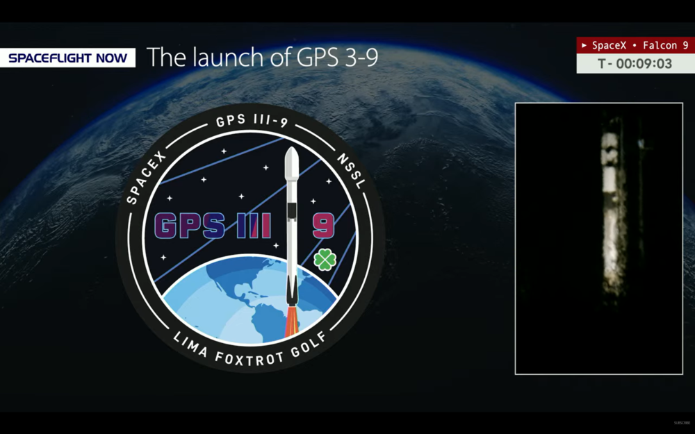
Update: The ninth GPS III satellite was successfully launched into orbit Tuesday.
Pre-launch report
GPS III Space Vehicle SV09 is being prepped for launch from Space Launch Complex (SLC)-40 at Cape Canaveral Space Force Station, Florida, aboard a SpaceX Falcon 9 rocket.
The launch, delayed from Jan. 25, is now scheduled for 11:38 p.m. ET on Tuesday, Jan. 27.
A live webcast of this mission from launch to satellite deployment will begin about ten minutes prior to liftoff and can be watched on www.spacex.com/launches. The webcast will be shown on the X TV app, as well as various streaming outlets, including YouTube.com via SpaceFlight Now and NASASpaceflight.com.
U.S. Space Force’s Space Systems Command (SSC) and Combat Forces Command (CFC) will launch SV09 as the next National Security Space Launch (NSSL). The two field commands are executing this mission using the model established by the Rapid Response Trailblazer launch in December 2024 and GPS III-7 (SV08) launch in May 2025. Being pre-postured with the right equipment has enabled the launch teams to process and integrate the GPS III (SV09) satellite with the Falcon 9 rocket on a shortened timeline, the Space Force said.
GPS III satellites, equipped with M-code technology, provide the warfighter with a significantly more accurate and jam-resistant capability. Adding another such satellite to the constellation enhances the system’s robustness and ultimately boosts the warfighting lethality of the Joint Force.
The space vehicle was successfully delivered to Florida over-the-road on July 31, 2025. Now, CFC’s Mission Delta 31 is leading the pre-launch processing of the space vehicle, working alongside Lockheed Martin to integrate it onto the rocket and for launch in a faster timeline than in the past.
“This mission represents an outstanding collaboration across multiple teams and agencies,” said U.S. Space Force Col. Stephen Hobbs, MD 31 commander. “It foot stomps our ability to rapidly deploy a high-value space asset, in this case, an additional M-Code-capable satellite that brings significant, immediate value to the Joint Force.”
SV09 is named in honor of Col. Ellison Onizuka, a U.S. Air Force test pilot and NASA astronaut. Onizuka successfully flew on STS-51C, a space shuttle Discovery mission in January 1985. The naming of the satellite also honors his memory as one of the astronauts who perished during the launch of STS-51L aboard the space shuttle Challenger on Jan. 28, 1986.
With the launch of SV09, the GPS III constellation gains another satellite equipped with significantly enhanced accuracy and jam-resistance, bolstering the capabilities of the Joint Force.
The Coastal States of the Baltic Sea and the North Sea have published an open letter to the international maritime community insisting on the protection of GNSS-based navigtion. The countries point the finger squarely at the Russian Federation for causing disruption in both critical navigation and timing services for sea vessels.
“Modern maritime transport is fundamentally built on the reliability of satellite-based navigation,” reads the letter. “For over three decades, global shipping has advanced by developing vessel operations to increasingly depend on the position, timing and navigation data provided by satellite systems. This shift has brought great efficiency but has also created a new dependency.
The letter highlights the importance of GNSS as a critical safety requirement, not only ship navigation but also precise time synchronization vital for systems such as the Global Maritime Distress and Safety System (GMDSS).
Risks to the Automatic Identification System
Another GNSS service, the Automatic Identification System (AIS), plays a key role in traffic coordination, situational awareness and emergency response. “Spoofing or falsifying AIS data undermines maritime safety and security, increases the risk of accidents, and severely hampers rescue operations,” the letter states.
“We are now facing new emerging safety situations due to growing GNSS interference in European waters, particularly in the Baltic Sea region. These disturbances, originating from the Russian Federation, degrade the safety of international shipping. All vessels are at risk.”
The countries ask for cooperation developing alternative terrestrial radionavigation systems as a GNSS backup. They also want vessels crews properly trained to operate safely during navigation system outages.
“Maintaining trust in maritime navigation requires more than technology – it demands responsibility, transparency, and decisive action,” the letter states. “We must ensure that our seas remain safe, including when systems fail or face disturbances.”
The U.S. Space Force has ended an exploratory effort to add smaller, lower-cost navigation satellites to strengthen the existing GPS constellation, reports Space News.
The Space Force does not plan to move forward with on-orbit demonstrations of industy-designed smallsats under the Resilient GPS (R-GPS) program, which began in 2024. In September of that year, the Space Force selected Astranis, L3Harris Technologies and Sierra Space to develop concepts for small, cost-effective navigation satellites to increase GPS resilience, using an expedited “quick start” contract process.
But funding for the next phase of the program was not included in the fiscal year 2026 budget because of higher Department of the Air Force priorities, according to the report.
R-GPS was part of a broader push by the Pentagon to diversify satellite architectures amid concerns that spacecraft are vulnerable to interference or attack.
The Space Force has not said whether it plans to pursue alternative positioning, navigation and timing (PNT) efforts in place of R-GPS.
Lawmakers have repeatedly raised concerns about GPS vulnerability and have called for studies examining commercial low Earth orbit navigation services as potential complements or backups to GPS.
Tokyo-based satellite company ArkEdge Space Inc. has signed letters of intent with three international organizations to develop a PNT satellite network in low-Earth orbit (LEO).
The agreements with TrustPoint Inc., the Royal Institute of Navigation in the United Kingdom and FrontierSI aim to strengthen satellite-based PNT capabilities for civil, commercial and security applications.
The collaboration represents an early phase in ArkEdge Space’s effort to build international partnerships for PNT infrastructure. The company, which designs and operates small satellite constellations, said the project will focus on improving resilience of positioning and timing systems that support critical infrastructure.
The partners plan to examine policy frameworks and national PNT strategies as the project moves into a demonstration phase. ArkEdge Space said it will expand its network of international partners to support the development of space-based positioning systems.
“By working together, this collaboration represents an important step as we accelerate the development of resilient, trusted PNT capabilities that support critical infrastructure and informed decision-making worldwide,” ArkEdge Space CEO Takayoshi Fukuyo said.
TrustPoint has transmitted its first Low-Earth Orbit Navigation System (LEONS) time-transfer and tracking signals from a ground node to spacecraft in orbit. The milestone advances the development of commercial navigation infrastructure independent of GPS.
GNSS satellites require knowledge of their own time and orbital position to provide accurate data to Earth-based users. Most LEO spacecraft currently rely on GPS or medium-Earth orbit (MEO) signals for that information. Interference and jamming are increasingly affecting these LEO connections, degrading or blocking signals.
LEONS provides GPS-independent time transfer and orbit tracking. Initially developed for TrustPoint’s planned constellation, the system can be adapted for other LEO operators requiring timing and navigation for their spacecraft. The ground-to-space infrastructure is designed to support a GPS-independent PNT layer in orbit.
“With the pace of modern threats accelerating, the difference between concepts and capabilities matters,” said Nicole Hilliard, director of government programs at TrustPoint. “This milestone demonstrates that commercial partners can field resilient, GPS-independent PNT capabilities that strengthen national security architectures and justify continued investment in companies that deliver.”
The demonstration supports TrustPoint’s participation in the SpaceWERX AltPNT Challenge, which awarded the company two contracts to develop alternative PNT capabilities. The program seeks to deploy new options for precise, dual-use PNT systems.
Throughout the past several decades, GNSS has become one of the most significant technologies in modern engineering, supporting transportation, communications, finance, emergency response, and critical infrastructure [1]. Its precision, global reach, and reliability have enabled entire industries to scale in ways that would otherwise have been impossible. Yet as GNSS is used more deeply in autonomy-driven and safety-critical domains, the limitations of relying on a single-layer PNT architecture are becoming increasingly apparent.
Urban canyons degrade satellite geometry and tracking performance; intentional and unintentional interference is now commonplace [2]; spoofing has shifted from a theoretical concern to an operational reality; and indoor environments, which are essential for robotics, logistics, and emergency services, remain largely outside GNSS’s physical reach. These challenges are not shortcomings of GNSS itself. They reflect what the system was originally designed to provide: a globally available positioning and timing reference, not the entire resilience burden for every PNT-dependent application.
In parallel, communications technologies have undergone rapid transformation. The evolution from LTE to 5G, and soon to 6G, has introduced wider bandwidths, massive MIMO antenna arrays, improved network synchronization, and dense deployment across urban and indoor environments [3]. At the same time, LEO broadband constellations have matured into powerful satellite infrastructures capable of delivering strong signals, rapid Doppler dynamics, and frequent visibility. Although these systems were built primarily for data connectivity, their physical characteristics naturally lend themselves to positioning and timing.
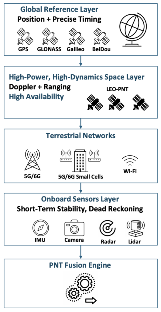
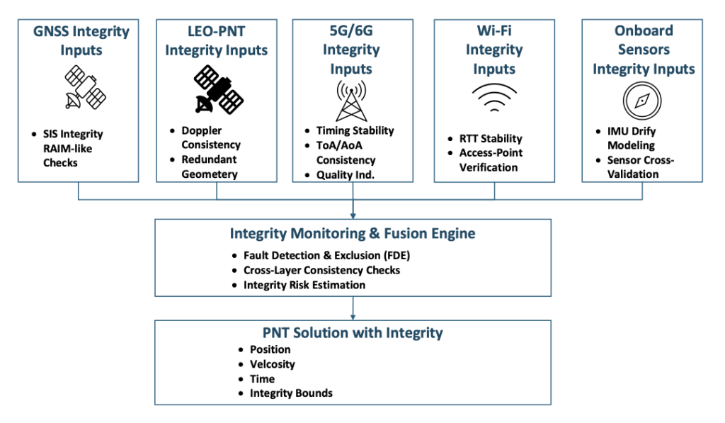
Taken together, these developments point toward a new direction for resilient PNT: a multi-layer architecture in which GNSS serves as the global reference layer and is complemented by high-power, high-dynamics LEO satellites, terrestrial 5G/6G networks and Wi-Fi systems, and a suite of onboard sensors that provide short-term stability and dead-reckoning capability. Figure 1 illustrates this emerging architecture and highlights how each layer contributes specific observables, coverage strengths, and levels of robustness. The remainder of this article examines the physical foundations of communications-based PNT, the role of LEO as an augmentation space segment, the engineering challenges inherent in multi-source navigation, and the system-level architecture that is now taking shape to deliver resilient and ubiquitous PNT.
Figure 1. Multi-layer architecture for resilient PNT. (All figures provided by the author)
2. 1 Growing Dependence on PNT and GNSS Vulnerability
Nearly every sector of modern life depends on GNSS-based positioning and timing. As reliance grows, exposure to GNSS limitations grows with it. Dense urban environments create severe multipath and signal blockage; jamming and spoofing incidents are now regularly reported near conflict zones and busy ports [4]; and autonomy concepts in aviation and ground mobility increasingly assume reliable PNT even when GNSS performance is degraded or unavailable.
GNSS will remain the global reference layer, but it was never intended to carry the full burden of these mission-critical demands on its own. A complementary set of technologies is needed, systems that continue to function in GNSS-challenged environments and provide redundancy when satellite signals are unavailable, corrupted, or intermittent.
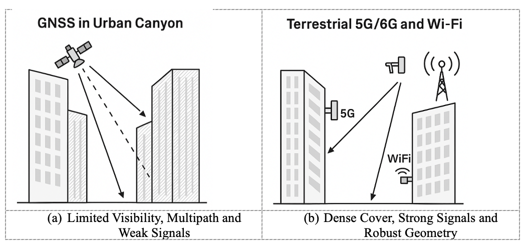
Error! Reference source not found. illustrates this challenge in a representative urban-canyon environment. Tall buildings restrict line-of-sight to GNSS satellites and generate strong multipath reflections, resulting in weak and unreliable signals (Figure 2a). By contrast, terrestrial networks such as 5G/6G and Wi-Fi maintain strong signal levels and robust geometry because their transmitters are embedded within the built environment, often only tens or hundreds of meters away (Figure 2b). This complementary coverage is a fundamental motivation for integrating communications signals into future PNT architectures.
Figure 2. Comparison of GNSS and terrestrial network coverage in urban canyons.
2.2 Communication Networks Have Quietly Become PNT-Capable
Modern communication networks have evolved far beyond their original purpose of data transport [5]. Several physical-layer characteristics now make 5G, Wi-Fi 7, and future 6G systems surprisingly well suited to PNT:
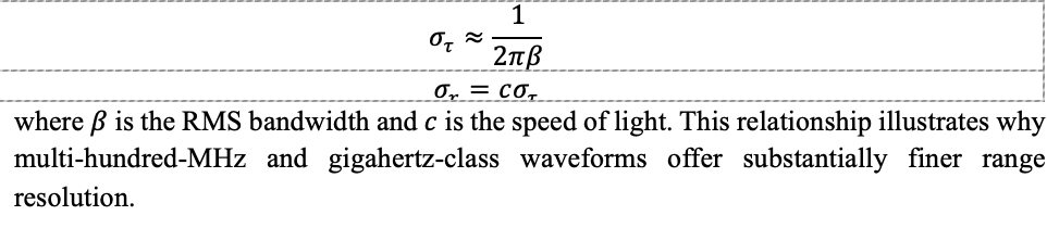
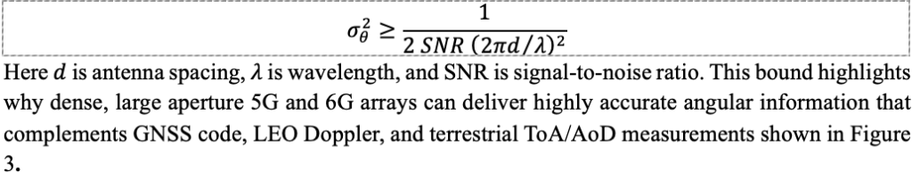
Wideband signals. Wi-Fi 7 supports 320-MHz channels and 5G FR2 offers up to 400 MHz, with multi-GHz bandwidths anticipated for 6G [6]. Wider bandwidth directly improves time-of-arrival (ToA) precision. The ToA uncertainty can be approximated by:
Massive MIMO. Multi-element antenna arrays estimate angle-of-arrival (AoA) and angle-of-departure (AoD), effectively turning base stations into spatial sensors capable of separating line-of-sight from multipath.
Dense deployment. Unlike GNSS satellites, orbiting at roughly 20,000 km, terrestrial networks are woven directly into the environment. Small cells and access points provide excellent geometry in exactly the locations where GNSS performance is weakest, including city centers, campuses, factories, and warehouses.
High signal power. Terrestrial signals arrive at the receiver tens of decibels stronger than GNSS, improving indoor penetration, acquisition speed, and robustness to interference.
These features were introduced to enhance connectivity, yet they collectively create an RF landscape that is inherently PNT-capable.
2.3 The Rise of LEO Constellations as a Complementary Space Layer
A third major driver behind communications-enabled PNT is the rapid proliferation of LEO satellite constellations. Broadband systems such as Starlink and OneWeb, together with several emerging PNT-dedicated LEO constellations, offer distinct advantages [7]:
Stronger received power. LEO satellites operate at altitudes of roughly 500–1,200 km, far closer than GNSS satellites at 20,000 km or higher, resulting in significantly stronger received signals.
Rapid Doppler dynamics. The relative motion of LEO satellites produces large, fast-varying Doppler shifts, which improve observability of user velocity and, over short intervals, position.
Large constellation sizes. Hundreds or thousands of satellites create rich geometry and frequent visibility, enhancing availability and resilience.
Although many LEO systems were designed primarily for communications, their signals can already be exploited opportunistically for positioning and timing. Purpose-built LEO-PNT systems extend these capabilities by offering wideband navigation signals, multi-frequency operation, and security features intended specifically for resilient PNT [7].
These characteristics make LEO a natural augmentation layer, strengthening GNSS performance and providing additional robustness in degraded, obstructed, or contested environments.
3. Technical Foundations of Communications-Based PNT
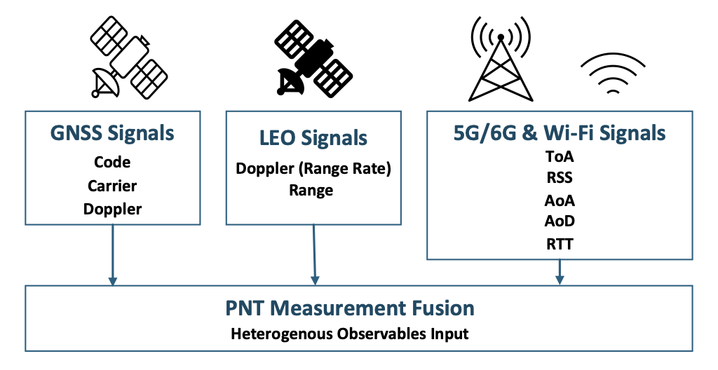
Modern communication and LEO satellite systems provide a diverse set of physical-layer measurements that can be fused with GNSS to create a resilient, multi-layer PNT solution. These observables go well beyond traditional GNSS code and carrier measurements and include Doppler, ranging, time-of-arrival, round-trip time, angle-of-arrival, angle-of-departure, and received signal strength. Figure 3 summarizes this heterogeneous measurement landscape and shows how each layer contributes distinct observables to the fusion engine.
Figure 3. PNT measurement diversity across GNSS, LEO-PNT, and terrestrial networks.
3.1 High-Resolution Ranging from Wideband Waveforms
Ranging accuracy is fundamentally linked to signal bandwidth. GNSS signals typically occupy 1–20 MHz, whereas modern communication waveforms may span hundreds of megahertz. Wider bandwidth enables finer temporal resolution, allowing receivers to separate closely spaced multipath components and improve time-of-arrival (ToA) precision [6].
In practice, Wi-Fi 7 and 5G FR2 waveforms can support sub-meter ranging in favorable conditions and substantially enhance relative positioning indoors and in dense urban environments. Techniques such as two-way ranging, cooperative localization, and inertial smoothing can extend performance even further. As shown in Error! Reference source not found., these wideband ToA and RTT observables form an essential input to the PNT measurement fusion layer.
3.2 Spatial Sensing with Massive MIMO
Massive MIMO arrays are one of the most powerful enablers of communications-based PNT. By comparing the phase and amplitude across many antenna elements, base stations estimate angles of arrival (AoA) and departure (AoD), turning terrestrial infrastructure into distributed RF sensor arrays [8].
Angle-based measurements offer several important benefits:
Improved localization geometry in 3D urban canyons
Ability to distinguish line-of-sight (LOS) from multipath
High update rates suitable for UAVs and advanced air mobility (AAM) platforms
A simplified Cramér–Rao lower bound (CRLB) illustrates how antenna geometry and signal power influence the accuracy of AoA estimation:
3.3 Infrastructure Density and Geometric Strength
From a PNT perspective, measurement geometry can be as important as measurement precision. Dense deployments of base stations, small cells, and access points give 5G, 6G, and Wi-Fi networks inherently strong geometric diversity, especially in environments where GNSS geometry collapses.
In indoor settings or street canyons, a receiver may have ten or more RF sources within a few hundred meters. This density improves dilution of precision (DOP), increases redundancy, and enables fallback positioning even when GNSS availability drops to zero. Within the multi-layer architecture described in Figure 1, terrestrial networks therefore provide crucial observability in GNSS-restricted environments.
3.4 High Signal Power and Robust Tracking
Terrestrial and LEO communication signals enjoy a link-budget advantage of roughly 50–100 dB over GNSS. This additional power yields several practical benefits:
Better performance with small or non-ideal antennas
Increased resilience to interference and jamming
Faster acquisition and re-acquisition after outages
More reliable tracking under fast dynamics or partial obstruction
In many scenarios, 5G, Wi-Fi, and LEO signals remain trackable long after GNSS signals fall below usable thresholds, providing essential continuity for navigation filters and multi-sensor fusion engines.
3.5 Timing and Synchronization in Communication Networks
Modern wireless networks rely on tight synchronization for scheduling, beamforming, and coordinated MIMO. They obtain timing from GNSS, fiber distribution, and packet-based protocols such as IEEE 1588 Precision Time Protocol (PTP) [9]. As these timing infrastructures mature, communication networks increasingly become timing providers rather than solely timing consumers.
Although terrestrial networks do not yet match the long-term stability of GNSS-disciplined oscillators, they provide valuable short-term holdover and regional timing continuity. These capabilities play an important role in multi-layer PNT systems, particularly during GNSS outages.
4. Engineering Challenges and Limitations
Although communications-based PNT provides powerful complementary capabilities, significant engineering challenges remain. These challenges do not diminish the value of multi-layer PNT; rather, they highlight the technical rigor required to deploy these systems reliably on a scale.
4.1 Multipath and Non-Line-of-Sight Propagation
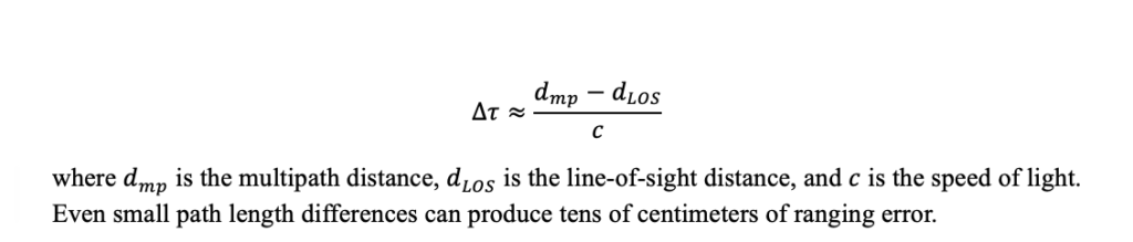
For terrestrial PNT, multipath and non-LOS propagation remain the dominant contributors to ranging and angle errors. Buildings, vehicles, reflective indoor structures, and metallic industrial environments introduce secondary paths that bias ToA, RTT, AoA, and Doppler measurements. A simplified model of multipath-induced ToA bias is:
Massive MIMO beamforming, high-resolution channel estimation, and machine-learning LOS classifiers can mitigate these errors, but performance is highly environment-dependent and cannot be guaranteed in all cases. Figure 3, introduced earlier, highlights how diversity in measurement types helps reduce susceptibility to any single error mechanism.
4.2 Synchronization Constraints and Timing Drift
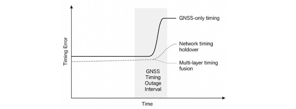
Communication networks require precise time alignment for scheduling, beamforming, and coordinated MIMO. However, network clocks do not yet match the long-term stability of GNSS-disciplined oscillators. Backhaul delay variability, oscillator drift, and partial GNSS visibility at base stations introduce timing uncertainty that must be explicitly modeled in a PNT fusion engine.
Figure 4 illustrates timing error growth during a GNSS outage, comparing:
GNSS-only timing, which diverges quickly without satellite visibility
Network timing holdover, which slows but does not halt drift
Multi-layer timing fusion, which maintains the lowest error accumulation
These behaviors demonstrate why communication-based timing is best used as a complementary layer rather than a standalone reference.
Figure 4. Timing error comparison during a GNSS timing outage.
4.3 Waveform and Structural Limitations
Modern communication waveforms such as OFDM were optimized for throughput and spectral efficiency, not navigation. Several characteristics constrain raw positioning performance:
Finite pilot density limits effective ranging bandwidth
High peak-to-average power ratio (PAPR) stresses nonlinear receivers
4.4 Coverage Variability and Regulatory Constraints
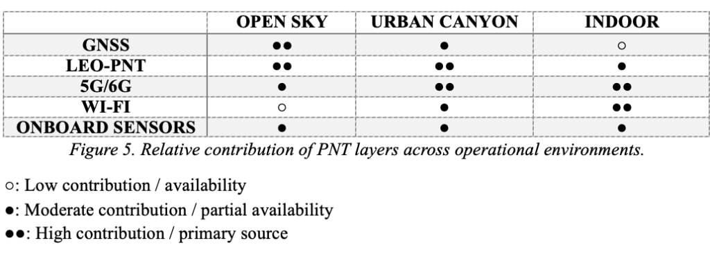
Terrestrial network density varies sharply by geography. Urban cores, industrial sites, and indoor campuses enjoy strong 5G/6G and Wi-Fi coverage, whereas rural, maritime, and mountainous regions may see limited improvements without LEO-PNT augmentation. Spectrum policy, privacy rules, and operator-controlled access to timing and positioning features further constrain how widely these capabilities can be exposed. Figure 5 summarizes the relative contribution of each PNT layer—GNSS, LEO-PNT, terrestrial networks, and onboard sensors—across open-sky, urban, and indoor environments.
Figure 5. Relative contribution of PNT layers across operational environments.
4.5 Security and integrity
As communication signals begin supporting navigation functions, they must meet higher standards for robustness, integrity, and security. PNT observables are vulnerable to spoofing, replay, meaconing and cyber-attacks on timing sources [10]. GNSS experience demonstrates the value of:
Cross-layer consistency checks
Cryptographic authentication
Fault detection and exclusion (FDE)
Monitoring for anomalies in Doppler, timing, or angle domains
Redundancy across multiple constellations and layers.
These functions are visualized in Figure 6, which illustrates how a multi-layer PNT system performs integrity monitoring across heterogeneous measurements.
5. A Multi-Layer Architecture for Future PNT
The earlier sections described why GNSS alone cannot meet emerging PNT requirements and how communications and LEO signals provide new sources of observability. Building on those foundations, Figure 1 introduces a multi-layer architecture in which GNSS, LEO-PNT, terrestrial networks, and onboard sensors cooperate to deliver resilient positioning and timing. This section outlines the role of each layer and how they integrate into a unified system.
5.1 GNSS as the Foundational Global Layer
GNSS will continue to provide the global reference frame, absolute positioning, and precise timing that anchor the entire architecture. Its worldwide availability, mature error modeling, and extensive user base make it the natural reference for other layers to align with whenever GNSS is available and reliable. In this sense, GNSS remains the “truth model” for time and coordinates, even as additional layers enhance resilience.
5.2 LEO-PNT as the High-Power, High-Dynamics Space Layer
LEO satellites provide diversity in orbit, signal power, geometry, and dynamics. Their lower altitude results in significantly stronger signals and rapid Doppler variations that improve motion observability. These characteristics reinforce GNSS performance in interference, urban canyon, and high-dynamics environments. As shown in Figure 3, LEO adds Doppler-based range-rate observables that are particularly valuable for maintaining continuity when GNSS quality fluctuates.
5.3 Terrestrial Networks as the Urban and Indoor Layer
5G, Wi-Fi 7, and future 6G networks form the densest PNT-capable infrastructure ever deployed. Their wideband signals, massive MIMO arrays, and strong received power position them as the dominant layer for indoor and urban navigation. Where GNSS geometry collapses, terrestrial networks provide ToA, AoA, AoD, RTT, and coverage exactly where users most often need it. Figure 5 highlights how their contribution becomes primary indoors and highly complementary in urban canyons.
5.4 Onboard Sensors and Local References
IMUs, odometry, barometers, cameras, radar, and lidar provide short-term stability and immediate awareness of the immediate environment, independent of external RF conditions. These sensors bridge outages and reduce reliance on any single external signal source. Their role within architecture mirrors their role in autonomy today: providing the continuity needed when GNSS, LEO, or terrestrial signals fluctuate. Together with RF observables, they form a robust solution space consistent with the measurement diversity shown in Figure 3.
5.5 Fusion, Standards, and System Engineering
Realizing a multi-layer PNT system is fundamentally a system-engineering effort. Success depends on:
Common timing and reference frameworks across GNSS, LEO, and terrestrial layers
Standardized quality indicators and integrity metrics
Interfaces that expose PNT-relevant observables from communication networks while respecting privacy and operational constraints
Cross-layer consistency checks that ensure no single measurement dominates unchecked
Standards bodies, including 3GPP, IEEE and aviation authorities, are beginning to address these needs, but operationalizing multi-layer PNT at scale will require continued collaboration across industries. Figure 6 illustrates how integrity information from each layer contributes to fault detection, cross-checking, and integrity-bound estimation within the fusion engine.
Figure 6. Integrity monitoring in multi-layer PNT architecture.
6. Conclusion
The era of single-layer PNT is coming to an end. As reliance on precise positioning and timing accelerates across aviation, ground autonomy, critical infrastructure, and networked systems, GNSS alone cannot shoulder the growing resilience burden. Fortunately, a rich set of complementary technologies already surrounds us. Dense terrestrial networks, emerging LEO constellations, and increasingly capable onboard sensors provide observables that naturally augment GNSS and extend PNT into environments where satellite signals struggle.
The opportunity now is to treat communications and PNT not as separate domains but as elements of a unified system. A multi-layer architecture — such as the one outlined in this article — offers stronger availability, improved measurement diversity, and inherent resilience against interference, outages, and environmental constraints. The key challenge ahead lies not in inventing new signals, but in system engineering: establishing shared timing frameworks, standardizing measurement interfaces, ensuring integrity across heterogeneous sources, and building trust in signals not originally designed for navigation.
Most of the technical ingredients are already in place. The next decade will determine how effectively industry, government, research institutions, and standards bodies can integrate them into certifiable, interoperable, and widely deployable solutions. If successful, multi-layer PNT will become a foundational capability — providing trustworthy positioning and timing wherever future autonomous systems, vehicles, and critical infrastructure require it.
To celebrate 30 years of the Galileo global navigation system, the European Space Agency created the following video. Astronomer Galileo Galilei makes an appearance.
“Three decades of challenges and triumphs that have shaped the navigation systems we rely on today: EGNOS and Galileo, and that serve as a legacy to building the satellite navigation systems of tomorrow,” states ESA.
In October 1995, the ESA Council at Ministerial Level approved ARTES Element 9, initiating the studies and development of GNSS-1 (EGNOS) and GNSS-2 (Galileo). However, the first steps leading to this moment started as early as the 1980s, with pioneering research and studies conducted by ESA, national space agencies and European institutes.
Today’s commercial innovation requires infrastructure that moves at the same pace.
Essence
The rise of commercial satnav
Everyday life is saturated with location-dependent devices. They are multiplying faster than ever and their requirements have surpassed what GPS can support. Innovation in low-Earth orbit (LEO) satellites have seen exponential growth in the last ten years, unlocking new possibilities in further connecting our world.
In 2016, the total number of satellites operational in space from commercial and government operators was approximately 1,500. This number had been stable for decades, with linear growth since the launch of Sputnik in 1957. Today, there are now more than 8,000 satellites operational in space — with nearly all growth happening in LEO.
There are multiple reasons why. The cost of space access has decreased with reusable rockets and greater competition. The demand for connectivity has driven deployment of multiple constellations to deliver Internet from space. Latency is extremely important in communications and resolution in Earth observation.
While innovation in LEO satellites has primarily focused on connectivity and Earth observation, there is a generational opportunity to innovate in the position, navigation and timing (PNT) infrastructure that silently powers modern life.
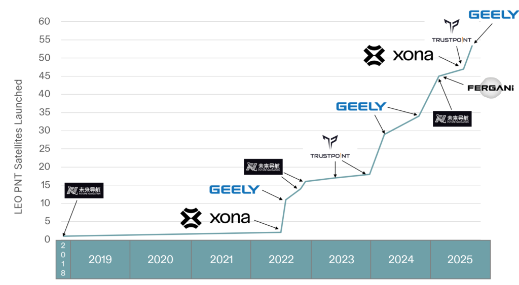
There are now more than ten entities working toward deployment of dedicated PNT functions in LEO, amounting to more than 2,500 satellites if every constellation was complete today. As shown in Figure 1, five of these entities have already collectively launched more than 50 satellites. This market signal is not surprising, as demand for greater precision, power and protection are becoming fulfilled with diversification in LEO.
Figure 1. Launches of LEO PNT satellites.
Essentials
Medium-Earth orbit (MEO) has been the traditional choice of satellite navigation for global systems, with GPS, Galileo, BeiDou and GLONASS all being deployed in this regime. This altitude in the outer Van Allen belts is the harshest radiation environment Earth orbit satellites are subjected to and is a major driver in the cost and complexity of the satellites. From a commercial standpoint, deployment in LEO is more attractive as the more benign radiation environment allows for the use of more commercial off-the-shelf (COTS) parts in satellite designs, facilitating volume production. With a healthy ecosystem and supply chain now developed around LEO for both satellites and launch vehicles, the opportunity for commercial PNT to set a new standard in performance and protection is open.
The time for innovation in PNT could not be more urgent. Innovators are pushing the frontiers of technology across every industry and market. Physical intelligence is proliferating in the form of self-driving cars, humanoid robotics, automated farming, unmanned aerial systems and more. As these systems begin to coexist in the real world, the tools they rely on have never been more at risk. Commercial aviation is regularly jammed in Europe and the Middle East due to ongoing conflicts. And ships at sea are struggling to adapt to an environment where spoofing is commonplace.
The commercial world has different and increasingly more stringent requirements than government-focused systems like GPS. GPS was designed primarily around military requirements and is longstanding infrastructure that is difficult to change with the myriad number of deployed devices that depend on it. This responsibility makes GPS too big to fail, but also incredibly difficult to change.
GNSS infrastructure has unlocked so much in commercial activity. There are now more devices using GNSS than the Internet, and GPS is by far the majority user of the technology (based on nearly 7 billion active GNSS devices on Earth and around 6 billion users of the Internet.) However, commercial users have limited input to the evolution of GNSS constellations, which has led to a widening gap between technology and wants, which provides for the current commercial opportunity.
Simply put, today’s commercial innovation requires commercial infrastructure that moves at the same pace to support.
Elements
Architecting LEO PNT
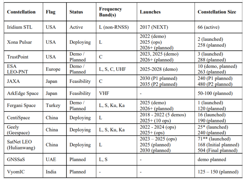
For a LEO satellite navigation system, many designs could be considered, as reflected in Table 1 from Reid et al. (2025) outlining current public information about systems already announced. These constellations range from government-supported systems, which could act as extensions of already deployed global or regional systems, to commercial systems that target potentially unique, independent markets.
Table 1. Comparison of dedicated LEO PNT systems, deployments, and plans. Note that satellites already deployed were verified on celestrack.org .
These constellations all have one thing in common: they aim for between 200 and 300 LEO satellites. The reason is simple: as LEO satellites have a footprint of approximately 1/10th that of medium Earth orbit (MEO) satellites, and between 20 and 30 MEOs are required for global PNT, approximately 10x more LEOs are needed to obtain similar coverage. A consequence is that in LEO, the radio energy is spread over 1/10th the area compared to MEO, which has implications for power needs at the satellite — 10x less in LEO for the same MEO power in the same band.
There is another crucial parameter to consider in LEO PNT design: spectrum. Table 1 shows that many approaches are being considered. Xona’s approach with its Pulsar constellation was centered around three major areas of commercial appeal: seamless operation with existing devices; increased native accuracy; and added resilience to jamming and spoofing. An important philosophy adopted early in the company’s culture was to not make development a science project — that is, do not reinvent the wheel, but rather upgrade the engine. GPS was a revolutionary technology, which is why it is so heavily adopted and brings so much value to the world. Therefore, stand on the shoulders of this giant to look out to the future.
Ease of integration was the first consideration, as it has been the most important aspect in accelerating adoption of any new system. And spectrum is key to Integration. By launching a new system that uses the existing L-band signals, the GNSS ecosystem producing approximately one billion new units per year can seamlessly upgrade their capability without new hardware. Xona’s first technology pathfinder satellite in 2022 validated this hypothesis. While the pathfinder mission supported two satellite frequencies already in the regional navigation satellite system (RNSS) bands — one near L-band E6 and the other in the yet unused C-band near 5 GHz — it became apparent that receiver companies were willing to develop hardware for the L-band signal, and did so quickly with their existing hardware. There was resistance and longer timelines to global adoption for C-band signals.
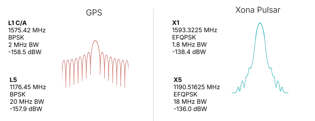
In response, Xona shifted the production signals to a dual L-band system, which already has nearly a dozen commercial receiver partners tracking the recently launched production satellite — some within weeks of the launch. The challenge is to choose a waveform that is near existing GNSS bands, familiar in form and function and digital signal processing techniques to what is already fielded today, and to not cause harmful interference to the existing GNSS services in orbit. The resulting design is shown in Figure 2, on the right. The key innovation was the selection of a bandwidth efficient form of quadrature phase shift keying (QPSK), which focuses the energy in the central lobe and rolls off quickly compared to a traditional binary phase shift keying (BPSK) signal, shown in Figure 2 on the left for comparison. The result is a 100x stronger signal that does not cause harmful interference to existing GNSS signals, while offering resilience through more signal power. This selection process was iterative, taking feedback from the receiver community. More information on the design and testing for compatibility can be found in Reid et al. (2025).
Figure 2. (Left) GPS BPSK-based signal waveform, and (right) Pulsar QPSK-based signal waveform.
In addition to compatibility and ease of integration, accuracy and resilience are critical design drivers. For example, farmers rely on their equipment positional accuracy to efficiently distribute seeds, fertilizer and water, reducing waste and improving crop yields. Positional accuracy also enables accurate, repeatable field operations year after year, saving time, fuel and money while protecting the soil. Because GNSS typically offers meter-level positioning, today many farmers buy positional accuracy through GNSS correction services to obtain centimeter-level positioning. The Xona architecture leverages these techniques in precise point positioning (PPP), delivering precise ephemerides direct from the space segment, and combining them with the fast motion from LEO satellites (compared to MEOs) to reduce position solution convergence times from ~10 minutes to nearly instantaneous (see, for example, Mah and O’Keefe, 2025). This geometry also boosts coverage, as correction services today typically rely on geostationary satellites and do not service high latitudes, where they would benefit missions such as mining operations for critical minerals and polar navigation.
Connectivity relies on resilient timing. Passing more data through a network means efficiently meshing data packets in synchronized manner. Telecommunications and data centers need such connectivity to function. Authentication is expected in our communications systems, which is largely unavailable in civil GNSS signals. In an age where GNSS spoofing is done to cheat at games like Pokémon Go and now more frequently for nefarious purposes, authentication becomes essential for a modern system (Anderson, 2025, and Xona, 2025a). For resilience to spoofing, Xona included not just data authentication, but also range authentication, so that users can ultimately authenticate their position.
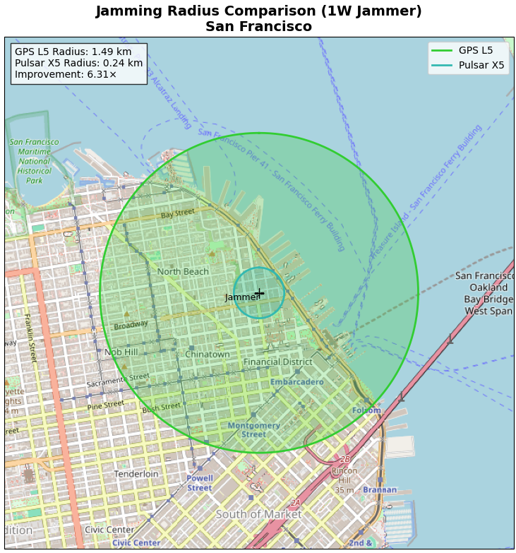
Defense applications require resilience to jamming. World conflicts, particularly currently in Ukraine and the Middle East, have showcased GNSS vulnerabilities in the presence of widespread GNSS jammers. However, this problem is no longer only a defense issue. In 2025, nearly 123,000 commercial flights in Europe were disrupted between January and April alone by GNSS jamming (GPS World, 2025). For resilience to jamming, one method is more power. LEO being 20x closer to Earth than MEO affords nearly a 10x boost in power for the same power transmitted at the satellite. Xona’s target was 100x more power to the end user to significantly reduce the effective range of a jammer by more than six times as shown by recent field trials. Such a transmission power translates to a >97% reduction in affected area and means threats shift to larger and less practical platforms for adversaries, i.e., from requiring handheld devices to backpacks or even truck-sized jammers.
More signal power also has implications for indoor positioning. Internet of things (IoT) devices such as asset trackers are commonly affected by signal obstruction and attenuation during transit, particularly in indoor environments, urban canyons, under foliage, or when obstructed by vehicles and cargo. Warehouses, shipping containers, and other constraints limit where position can be determined. Even coarse indoor positions can support operational intelligence for asset management.
Launching LEO PNT
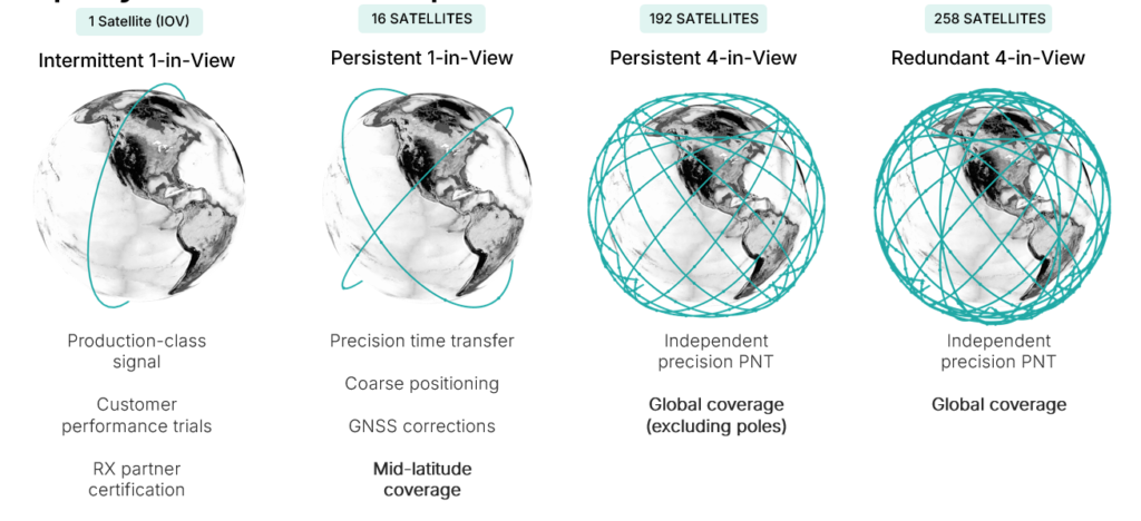
Pulsar is designed to launch in stages as shown in Figure 3, which unlocks capability in tranches that expands the number of features and ultimately the user base. While Pulsar will achieve persistent coverage across major markets at the deployment of 16 operational satellites, earliest customers in time transfer will see value from Pulsar much sooner as an independent source of timing synchronization for devices with holdover clocks. At 16 satellites, Pulsar will achieve persistent 1-satellite-in-view service, unlocking precise time transfer and coarse positioning for stationary users, including indoors. Pulsar also provides a link to stream GNSS corrections, building on a partnership with Trimble. Full resilient positioning will come online with GPS-level satellite visibility. First in the midlatitudes, with 192 satellites, and then globally with the deployment of an additional 66 satellites into polar orbit, bringing the total to 258 operational satellites.
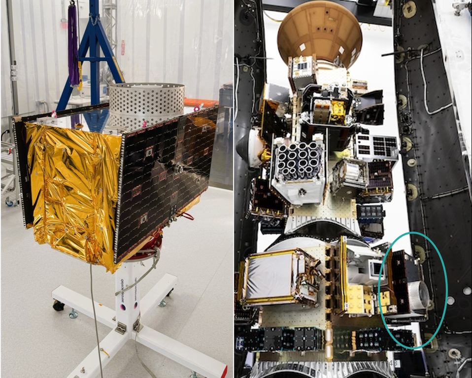
Xona launched its in-orbit-validation stage in June 2025 with Pulsar-0, the first production-class satellite representative of the scaled capability in terms of signal modulation, power and features. Pulsar-0 allowed for performance validation of the complete system, not just of the payload in space but also the tangible benefit to users on the ground. For scale, Figure 4 shows the 150 kg class satellite pre-launch, including its integration on the Falcon 9 launch vehicle. Launch cost has been become more accessible, unlocking the ability to launch larger spacecraft by commercial entities, which can have larger positive impact on the ground (Xona, 2025b).
Figure 4. Xona’s first production satellite Pulsar-0.
LEO PNT on-orbit
In almost 6 months since launch, Pulsar-0 has been tracked in more than 6 countries, 12 third-party receiver protypes, and has achieved several performance milestones that signal the groundbreaking capability Pulsar will deliver to users everywhere when the full constellation is operational. Early performance tests are built to showcase the value and features most important to commercial users in realistic settings.
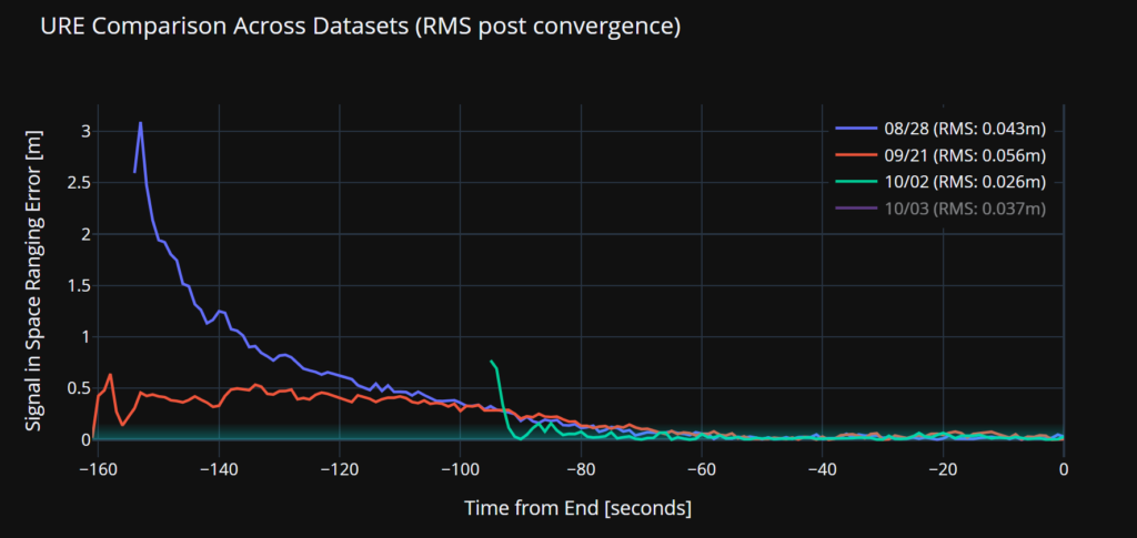
Accuracy. Figure 5 illustrates a signal-in-space user-range-error (SISRE) of 43 mm — about the diameter of a golf ball. This performance represents a more than tenfold increase in accuracy compared to that reported by GPS (Refro et al., 2024). The implication is an ability to natively perform PPP at the centimeter level, without an additional data link or correction layer.
Figure 5. Estimate of SISRE for Pulsar-0 ranging signal compared with nominal GPS.
Security. Xona is the first organization to show pseudorange authentication from orbit, accomplished using the Pulsar-0 satellite within weeks of the launch (Anderson, 2025). Pulsar is built from the ground up to be secure by design, combining cryptographic authentication of both navigation data and satellite ranging signals with rapidly authenticated signal verification — aiming for a time-to-authentication of approximately four seconds. This layered security significantly raises the technical and financial bar for would-be spoofers. A spoofer spoofing a single satellite continuously should succeed in fooling one second of a Pulsar receiver’s ranging once every 130 years (Xona, 2025a).
Jamming. Pulsar-0 signal testing has been conducted under live-sky jamming conditions at several jamming events, including Jammertest 2025 in Norway. These campaigns confirmed that using the Pulsar X5 signal can reduce the effective radius of a jammer by 6.3 times as compared to GPS L5 — in other words, less than 3% of the affected area compared to GPS. The same targeted power, bandwidth and type of jammer waveform was used against GPS and Pulsar, including center frequency. For context, Figure 6 shows the implications for a 1 Watt jammer scenario in San Francisco and the reduction brought by a 6.3x reduction in radius.
Figure 6. ffective jamming areas for Pulsar X5 and GPS L5 from a 1 W jammer in San Francisco based on Jammerfest 2025 test results.
Indoor. Data were collected for several navigation passes per day at multiple locations, including indoors. These include passes at Xona headquarters in Burlingame, California, and its office in Montreal, Canada. The most challenging indoor environment was Montreal, on the third floor of an industrial and primarily concrete building with two floors above. Figure 7 shows the Pulsar-0 power profile during a typical pass, peaking at the highest point in the sky. This structure is an artifact of the antenna gain pattern used in this mission. Designed for a higher altitude for deployment of later satellites, the pattern will be more isotropic with future satellites launched near 1100 km altitude compared to Pulsar-0, which is closer to 500 km. Near apex, the signal penetrates indoors, and this short segment proves to be sufficient for indoor positioning for stationary users. Leveraging techniques based on Doppler and including pseudorange, early results indicate sub-10 meters both outdoors and indoors.
Figure 7. Comparison of Pulsar and GPS signal strengths on roof and indoors at the Xona Montreal office.
EVOLUTIONARY
The coming years will be about gaining operational experience and in scaling the constellation with a near-term focus on the first batch of 16 satellites. Pulsar-0 has already confirmed its value proposition: attaining major milestones in performance including accuracy, security and jamming, but perhaps most importantly in the integration of user equipment. The next year is about working with customers in specific industries and use cases as Xona moves towards deployment of early operational service.
The future of LEO PNT is bright. Theory has evolved to prediction, which is now evolving to reality. The early results appear to lead to an exciting PNT future with LEO PNT expanding the GNSS revolution in terms of security, interference mitigation and system availability both outdoors and indoors for a myriad of current and new applications and users.
Further Reading
Anderson J (2025). World’s First Authenticated Satellite Pseudorange from Orbit, Proceedings of the 38th International Technical Meeting of the Satellite Division of The Institute of Navigation (ION GNSS+ 2025), Baltimore, Maryland, September 2025, pp. 738-748.
Eissfeller B, Pany T, Dötterböck D and Förstner R (2024). A Comparative Study of LEO-PNT Systems and Concepts, Proceedings of the ION 2024 Pacific PNT Meeting, Honolulu, Hawaii, April 2024, pp. 758-782.
Li W, Yang Q, Du X, Li M, Zhao Q, Yang L, Qin Y, Chang C, Wang Y, Qin G (2024). LEO augmented precise point positioning using real observations from two CENTISPACE™ experimental satellites. GPS Solutions, 28(1): 44.
Mah C, O’Keefe K (2025). Hardware Simulation of Low-Earth-Orbit GNSS for Carrier Phase Ambiguity Resolution, Proceedings of the 38th International Technical Meeting of the Satellite Division of The Institute of Navigation (ION GNSS+ 2025), Baltimore, Maryland, September 2025, pp. 2431-2443.
Prol FS, Ferre RM, Saleem Z, Välisuo P, Pinell C, Lohan ES, Elsanhoury M, Elmusrati M, Islam S, Çelikbilek K, Selvan K, Yliaho J, Rutledge K, Ojala A, Ferranti L, Praks J, Bhuiyan MZH, Kaasalainen S and Kuusniemi H (2022). Position, Navigation, and Timing (PNT) Through Low Earth Orbit (LEO) Satellites: A Survey on Current Status, Challenges, and Opportunities, IEEE Access, (10): 83971-84002
Reid TGR, Chan B, Goel A, Gunning K, Manning B, Martin J, Neish A, Perkins A and Tarantino (2020). Satellite Navigation for the Age of Autonomy, 2020 IEEE/ION Position, Location and Navigation Symposium (PLANS), Portland, Oregon, April 2020, pp. 342-352.
Reid TGR, Gala M, Favreau M, Kriezis A, O’Meara M, Pant A, Tarantino P and Youn C (2025). Xona Pulsar Compatibility with GNSS. Proceedings of the 38th International Technical Meeting of the Satellite Division of The Institute of Navigation (ION GNSS+ 2025), Baltimore, Maryland, September 2025, pp. 929-943.
Reid TG, Neish AM, Walter T and Enge PK (2018). Broadband LEO constellations for navigation. NAVIGATION: Journal of the Institute of Navigation, 65(2): 205-20.