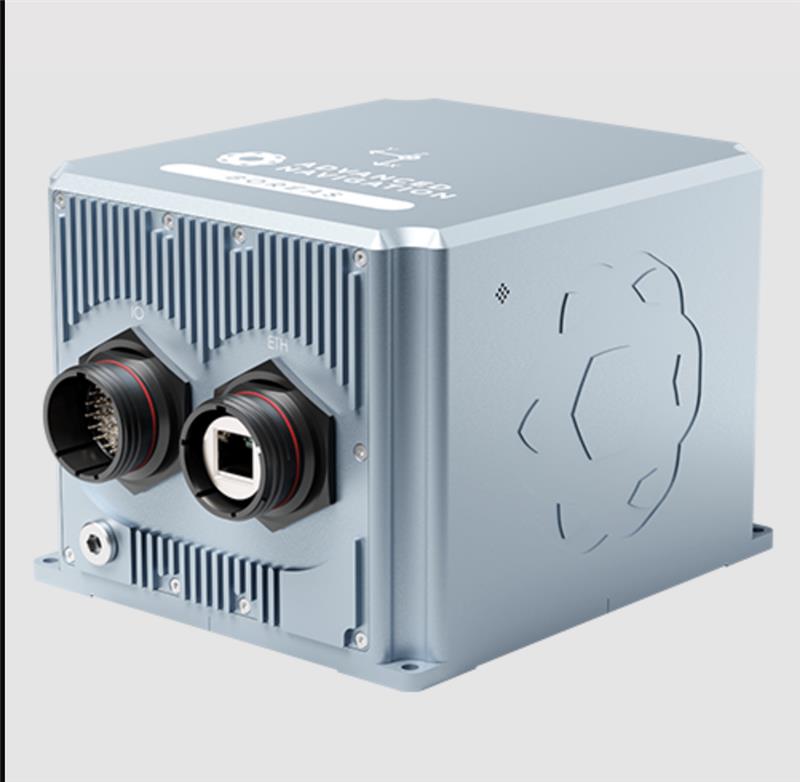
Advanced Navigation has expanded it Boreas digital fiber-optic gyroscope (DFOG) range, with the A series.
The Boreas A90 and A70 are strategic-grade inertial measurement units (IMU) that deliver acceleration and orientation with accuracy, stability and reliability under all conditions with no reliance on GNSS. They also feature automatic gyrocompassing.
The IMUs contain ultra-high accuracy DFOG and high performance closed-loop accelerometers. The Boreas A90 and A70 are both suitable for surveying, mapping and navigation across subsea, marine, land and air applications.
The Boreas A90 and A70 also offer an optional license to add INS capabilities and enable integration with external GNSS receivers using Advanced Navigation’s range of interfaces and communication protocols.
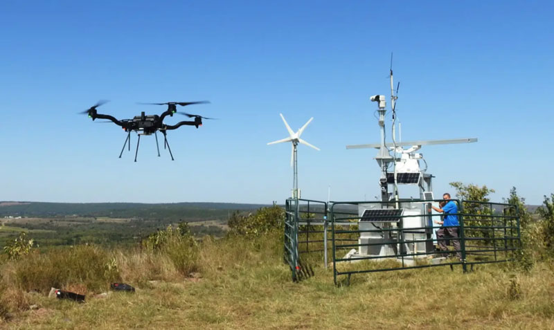
uAvionix has received Federal Communications Commission (FCC) approval, coordinated with the Federal Aviation Administration (FAA), to operate its SkyLink C-band command and control (C2) radios for beyond visual line of sight (BVLOS) operations at the Choctaw Nation of Oklahoma Emerging Technology test site.
The radios — operating on aviation-protected C-band frequencies — will be controlled by uAvionix’s SkyLine cloud-based C2 network solution that supports fleet management, network health monitoring, detect and avoid, and roaming between multiple radio networks and ground stations.
According to uAvionix, with the BVLOS Waiver, businesses looking to use aviation-protected C-band and other radio networks for assured control and non-payload communications can now develop, test and implement solutions for business initiatives such as package delivery and medical resupply.
With over 200,000 tribal members and more than 11,000 employees, the Choctaw Nation is the third largest Indian nation in the United States. It is developing an aviation test facility in southeastern Oklahoma that utilizes more than 44,600 acres of remote land it tribally owns to support the innovative research, development, test and evaluation of emerging manned and unmanned aerial system technologies in a safe and low-risk environment.
Interested businesses should contact the Choctaw Nation and uAvionix to support implementation and scaling of uncrewed aerial system operations with multiple C2 links including aviation protected C-band.
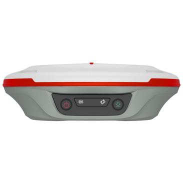
ComNav Technology has released the T20 palm real-time kinematic (RTK). The GNSS receiver with advanced technology is designed for surveying and mapping, GIS, marine, precision agriculture and machine control.
T20 is light, weighing in at 0.68 kg, and has low power consumption with 12 hours of battery life. It integrates functions such as a GNSS module, datalink module, 4G, 5.0 dual-mode Bluetooth, data memory system and more.
Powered by the SinoGNSS K8 high precision module, the T20 has 1,590 channels and can track all running and planned constellations including GPS, BDS, GLONASS, Galileo, QZSS and satellite-based augmentation systems. Additionally, the anti-interference algorithm enables the T20 to maintain accurate positioning and perform well in complex environments, providing surveyors with high-quality measurements.
The T20 is equipped with a third-generation inertial measurement unit from ComNav, which can be tilted and measured at an angle up to 60°. The T20 is also equipped with a U50 datalink module, which enables it to switch between base and rover.
The T20 is compatible with mainstream RTK receivers on the market.
A roundup of recent products in the GNSS and inertial positioning industry from the June 2023 issue of GPS World magazine.
SURVEYING
Survey Software Georeference raw lidar data
Georeferencer 2.5 featuring anyNAV software is suitable for survey applications. Users of Georeferencer 2.5 with the anyNAV feature enabled can boresight payloads and georeference lidar data using the user’s navigation data. The anyNAV software enables lidar surveyors to create accurate point clouds quickly. Georeferencer 2.5 now takes navigation data from third-party inertial navigation systems, which enables users to use that data to georeference raw lidar data from multiple sensor families. The resulting data can then be viewed in many point cloud viewer software packages. OxTS, oxts.com
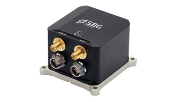
Inertial Navigation Solution Designed to deliver accuracy in challenging environments
Ekinox Micro combines a high-performance MEMS tactical inertial sensor with a quad-constellation, dual-antenna GNSS receiver, making it suitable for mission-critical applications. The device includes pre-configured motion profiles for land, air and marine applications, enabling the sensor and algorithms to be tuned for maximum performance in any condition. The device is designed for ease of use and integration, with simple connectors, a web configuration interface, datalogger, Ethernet connectivity, a PTP server, a REST API for configuration, and multiple input and output formats. Ekinox Micro is compatible with real-time kinematic (RTK) solutions and based on a tactical 0.8°/h class inertial measurement unit calibrated across the entire operating temperature range. It features accuracy roll/pitch of 0.015°, accuracy heading of 0.035°, and accuracy position of 1.2 m without any corrections or 1 cm in RTK. The device also meets the MIL-STD-461, MIL-STD-1275, and MIL-STD-810 standards. SBG Systems, sbg-systems.com
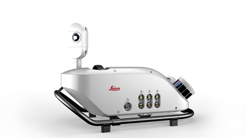
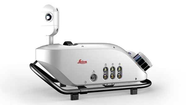
Lidar Sensor High-performance airborne bathymetric solution for deep water surveying
The HawkEye-5 increases survey efficiency by up to 25% compared to previous generations. The technology expands the capabilities of the Chiroptera-5 bathymetric lidar system, enhancing the productivity of applications such as nautical charting, environmental monitoring, and maritime surveillance in deep waters. The technology is designed to fit the Leica PAV100 gyro-stabilized mount, which isolates the sensor from unwanted aircraft movements — resulting in consistent data density and more efficient area coverage. The HawkEye-5 combined with the Chiroptera-5 features three lidar sensors, one four-band camera, and a QC camera to collect data from the seabed to land. Leica Geosystems, leica-geosystems.com
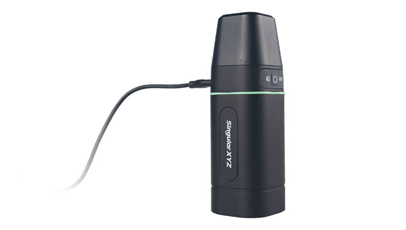
GNSS Receiver Complete with network RTK rover
The Sfaira One GNSS receiver is small and centimeter accurate. It provides users with an entry-level network real time kinematic (RTK) rover. Sfaira One is equipped with a GNSS module with 1,408 channels for GPS, BDS, GLONASS, Galileo and QZSS tracking — providing centimeter positioning in harsh environments. It also features advanced RTK and an anti-interference algorithm. The GNSS receiver connects via Bluetooth and can be configured to conduct surveying tasks on a smartphone. Additionally, Sfaira One supports SingularPad and SingularSurv software and is also compatible with mainstream field survey or GIS software. Sfaira One is IP65 dustproof and waterproof, which makes the receiver suitable for all weather conditions. It has a 4,800 mAh battery life with 16 hours working time and type-C interface that can be charged on-the-go with a power bank. SingularXYZ, singularxyz.com
MAPPING
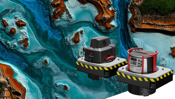
Mobile Mapping Solution Built for large-scale infrastructure measurement and digital twin creation
The Pegasus TRK100 is small and light, making it easy to mount on any vehicle. The mobile mapping system features the same modular hardware approach that enables users to add more cameras to expand the range of use cases. With its advanced mapping capabilities, the Pegasus TRK100 enables GIS professionals to visualize and understand the location of assets to help make the right decisions, improve asset management, and support infrastructure building and maintenance. The Pegasus TRK100 combines artificial intelligence and a learning algorithm to enhance and optimize the clarity of points in post-processing for improved accuracy. The versatility of the Pegasus TRK100 suits a variety of applications in diverse industries, including telecommunications, utilities and road maintenance. Leica Geosystems, leica-geosystems.com
OEM
Photo:
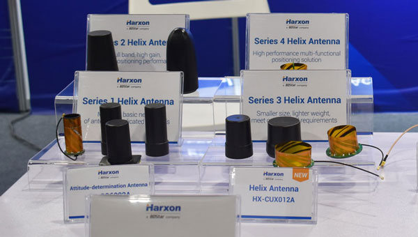
Helix Antenna Series Suitable for unmanned system applications
HX-CUX012A is designed with an extremely low profile, making it suitable for integration into UAVs, surveying and monitoring devices. It reduces the overall weight of applications, enables multipath mitigation and more. HX-CUX005A is a solution for integrated helix antenna applications. It is designed with the integration of a GNSS antenna and Bluetooth/Wi-Fi antenna, enabling communication and navigation without mutual interference. HX-CH7609A is a low profile and small size housed helix antenna. It has comprehensive GNSS support including GPS, GLONASS, Galileo, BeiDou, as well as L-band correction services. HX-CH7609A features centimeter phase center repeatability and high gain at a low elevation. With signal filtering and multipath rejection, it provides reliable and stable GNSS signals. HX-CHX600A is a high-performance helix antenna that receives GPS, Galileo, BeiDou, GLONASS, as well as L-band signals. With 4.2 dBi high gain, it provides suitable tracking performance at a low elevation angle. Its low noise figure design reduces transmission interference and improves signal quality. Harxon, en.harxon.com
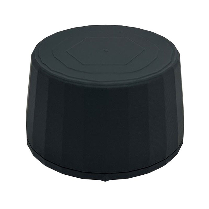
Helical Antenna Suitable for UAV applications
The HC990XF helical antenna is designed for precise positioning, covering the GPS/QZSS L1/L2/L5, QZSS L6, GLONASS G1/G2/G3, Galileo E1/E5a/E5b/E6, BeiDou B1/B2a/B2b/B3, and NavIC L5 frequency bands. This includes the satellite-based augmentation system (SBAS) available in the region of operation as well as L-band correction services. The HC990XF has a base diameter of 64 mm, is 37 mm tall and weighs 45 g. Its precision-tuned helical element provides full GNSS band coverage, suitable gain and axial ratio, and a tight phase center. The antenna base has an SMA (male) connector, three screw holes for secure attachment and an O-ring to waterproof the antenna connector. The HC990XF helical design does not require a ground plane, making it a suitable antenna for UAV applications. Tallysman Wireless, tallysman.com
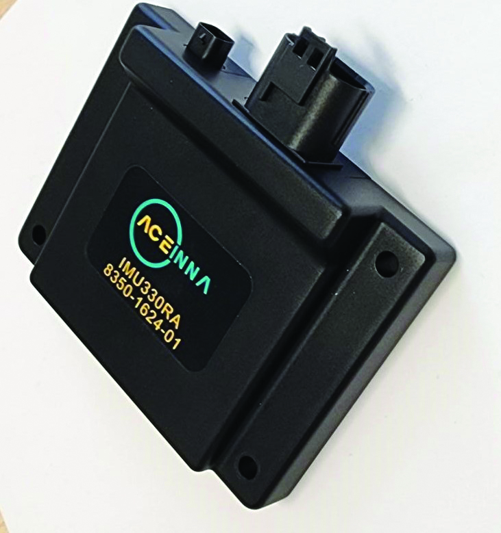
Inertial Module For automotive uses
The ASM330LHB automotive-qualified MEMS inertial-sensing module provides accurate measurements for a wide variety of vehicle functions. With the dedicated software provided, ASM330LHB also addresses functional-safety applications up to ASIL B1. ASM330LHB contains a 3-axis digital accelerometer and 3-axis digital gyroscope that provides a six-channel synchronized output. The module’s high-accuracy inertial measurements are used to improve the precise positioning of a vehicle. The accelerometer and gyroscope maintain high stability over time and temperature, and have very low noise for an overall bias instability of 3°/hour. Specified over the extended temperature range, -40°C to 105°C, the ASM330LHB has multiple operating modes that let designers optimize the data-update rate and power consumption.
ASM330LHB can support advanced driver assistance systems or vehicle-to-everything communication, as well as help stabilize sensing systems such as radar, lidar and visual cameras, and assist semi-automated driving applications up to L2+. Additionally, ASM330LHB can be used to enable a variety of functionalities in the body of a vehicle. ASM330LHB was developed with the automotive functional-safety standard ISO 26262 — the ASIL B compatible software library has been certified independently by TÜV SÜD. By implementing dedicated safety mechanisms, including data integrity and accuracy, the library ensures compliance with ASIL B automotive systems.
With the companion software engine, the ASM330LHB supports the growing adoption of automotive systems that require safety integrity up to level B. The combination of two ASM330LHB sensor modules for fail-safe redundancy delivers resilient contextual data for driver-assistance applications such as lane centering, emergency braking, cruise assistance and semi-automated driving. ASM330LHB is AEC-Q100 qualified and in production now in a 2.5 mm x 3.0 mm 14-lead VFLGA package. STMicroelectronics, st.com
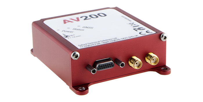
INS Built for automation applications
The AV200 is designed to give precise location data. It includes quad-constellation, dual-antenna, real-time kinematic (RTK) GNSS to provide users with position data as well as its temperature-calibrated, multi-core inertial measurement unit. These technologies give the AV200 position accuracy within 0.05 m, heading accuracy of 0.2°, and velocity accuracy of 0.2 km/h. The AV200 is built using the same technology that is commonly used for NCAP test validation, which has become the preferred technology for OEMs globally to test vehicles in both test-track and real-world scenarios. OxTS, oxts.com
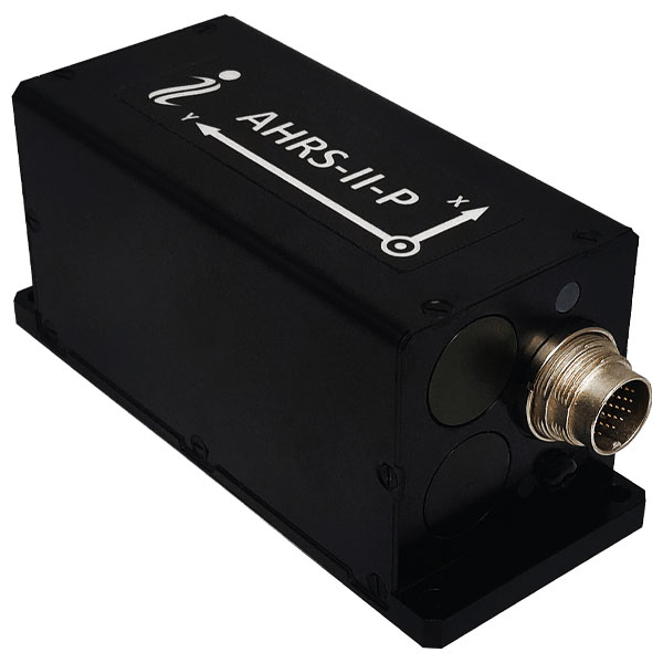
Reference System For attitude and heading
AHRS-II-P is an enhanced, high-performance strapdown system that determines absolute orientation (heading, pitch and roll) for any mounted device. The AHRS-II-P can determine orientation for both motionless and dynamic applications. The AHRS-II-P contains a tactical-grade inertial measurement unit (IMU) consisting of three high-precision MEMS accelerometers, three advanced MEMS gyroscopes and a high-precision, gyro-compensated, embedded fluxgate compass. It also uses 8 mm fluxgate magnetometers. This device is suitable for a variety of devices such as UAVs, antennas, ships and robotic devices.
Inertial Labs, inertiallabs.com
GNSS Receiver For accurate positioning and heading
As a high-precision integrated GNSS positioning and heading receiver, the A200 can track all existing and planned constellations — including GPS, BSD, GLONASS, Galileo, QZSS and SBAS — providing high-precision positioning and heading data for users. A200 is designed specifically for precision agriculture, machine control, fleet management, robot and other industries. The A200 is equipped with a K823 GNSS module. It also features 1,226 channels. The A200’s third generation IMU delivers fast initialization and ensures the output of heading during temporary GNSS signal loss. The built-in data link has low power consumption and a long working range. It also can be upgraded to a super-long-range data link module. ComNav Technology, comnavtech.com
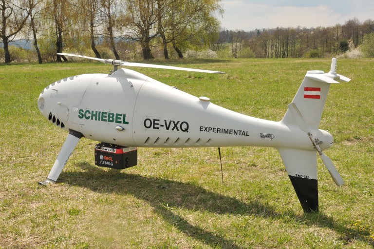
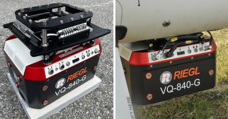
RIEGL Laser Measurement Systems GmbH and Schiebel have successfully completed the integration of a laser scanning system, the RIEGL VQ-840-G topo-bathymetric lidar sensor, on the Schiebel CAMCOPTER S-100 UAS. The RIEGL VQ-840-G, combined with the technical specifications and performance of the CAMCOPTER S-100 UAS, enables an efficient and secure way for surveying shallow waters, where monitoring from boats becomes a challenge.
The applications of airborne lidar bathymetry include the mapping of coastlines and riverbanks, as well as the monitoring of natural habitats, water reservoirs and hydraulic engineering applications.
In a single data acquisition mission, data below and above the water surface are covered.
Image: RIEGL
Additionally, the topographic laser scanners RIEGL VUX-1UAV/-LR and VUX-12023 can be integrated in the front payload bay of the CAMCOPTER S-100.
The VQ-840-G topo-bathymetric laser scanner is designed for use in a variety of maritime and hydrographic environments. The lidar sensor payload system is controlled remotely via a data link, which was crucial for the integration into the S-100 system.
The scanner is controlled by using the onboard software RiACQUIRE-Embedded via the available data link; data acquisition and laser safety are also monitored. Once the survey is completed, the raw data seamlessly integrates into the RIEGL data processing workflow.
OceanGate. (Credit: Screenshot of NBC news coverage)
On June 17, an OceanGate Expedition Titan submersible launched off the coast of Newfoundland, Canada, carrying five passengers to the bottom of the Atlantic Ocean to explore the infamous R.M.S. Titanic shipwreck. The U.S. Coast Guard said that the submersible lost contact with the surface vessel about an hour and 45 minutes after the launch and has not been in contact since.
The submersible can support life for 96 hours. As of the afternoon of June 20, it had 40 hours of oxygen left and U.S. and Canadian agencies were still searching for it.
The Titan submersible explained
According to the OceanGate website, the Titan is “a Cyclops-class manned submersible designed to take five people to depths of 4,000 [m] (13,123 [ft]) for site survey and inspection, research and data collection, film and media production, and deep-sea testing of hardware and software.” The Titan is equipped with an inertial navigation system (INS), an ultra-short base line acoustic positioning system, a robotics laser scanner, a Teledyne 2D sonar and more.
While it is equipped with an INS, the Titan relies on messages from a surface ship to guide the submersible to the shipwreck. The submersible and surface vessel rely on Elon Musk’s Starlink satellites for communication.
A part of the Titan worth mentioning, the crew is sealed inside and bolts are applied to the outside — needing an external crew to remove them upon surfacing.
Foreshadowing
The New York Postreported, in 2022, that an OceanGate Expedition to the Titanic lost contact for more than two hours and never found the wreck.
Aboard the submersible was a CBS correspondent, David Pogue, who was filming a segment for CBS Sunday Morning. He tweeted about the incident.
There are 18 planned expeditions to the Titanic with OcenGate Expeditions to survey the shipwreck, collect data, and document high-resolution images and videos.
The entire trip to the Titanic wreck site takes 8 days, and one dive can take up to 10 hours. The expedition is comprised of five legs.
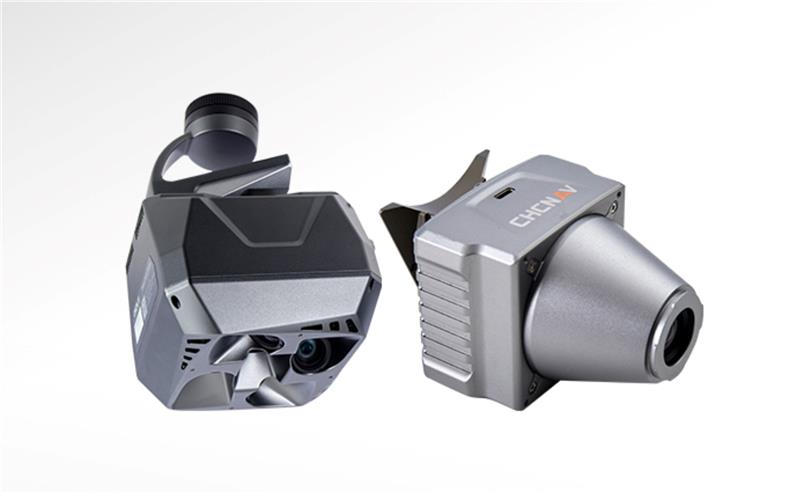
CHC Navigation has released the C5 and C30 orthographic and oblique cameras for aerial surveys. The systems are designed to provide high-quality imaging solutions for photogrammetric applications and to complement lidar survey data.
The C5 camera is an efficient and lightweight system for aerial surveys, weighing 290 g for increased flight endurance. Its compact size of 75 mm x 63.5 mm x 102.5 mm allows easy integration into UAVs. The C30 camera’s weight is 600 g with a size of 110mm x 108 mm x 85 mm. The C30 is also designed for aerial surveying.
The C5 and C30 cameras’ universal installation design makes them compatible with a wide range of fixed-wing and rotor UAV platforms. Both cameras are supported by the CHCNAV’s BB4 Mini and P330 Pro UAVs as well as the DJI’s M300 RTK.
The Alphaport (the A-type hardware interface) enables the C5 and C30 to be easily mounted into various UAVs and converted into the DJI Skyport connector for extended compatibility.
The C5 and C30 cameras give maximum flexibility for photogrammetric applications. They can be used independently on real-time kinematic-enabled UAVs to capture high-resolution imagery or installed directly on the CHCNAV’s lidar series to colorize point cloud data. This feature allows seamless imagery and lidar data integration for a more complete view of the surveyed area.
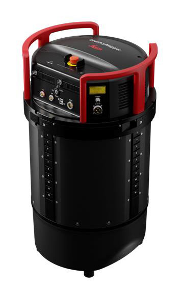
Leica Geosystems, part of Hexagon, has released the Leica CountryMapper for large-area imaging and lidar mapping. Combining a large-format photogrammetric camera with a high-performance lidar unit into a single system, the CountryMapper collects foundational geospatial data simultaneously to support a wide variety of user applications.
The CountryMapper combines imaging and lidar sensor modules into a highly efficient hybrid airborne system. The sensor features CMOS-based Leica MFC150 camera modules that leverage true mechanical forward-motion-compensation to deliver high image quality.
The sensor’s new Hyperion3 lidar unit features 60° field of view, improving the performance and flexibility of the system compared to previous lidar modules, while reduced laser divergence provides greater planimetric accuracy and better foliage penetration. The CountryMapper fully integrates with Leica HxMap multi-sensor end-to-end processing workflow, enabling distributed processing of images and point clouds to optimize productivity for very large data sets.
The CountryMapper supports applications such as orthophoto generation, terrain mapping, hydrography, forestry monitoring and infrastructure management. Users of previous-generation sensors can leverage their initial investment and upgrade their systems to the CountryMapper configuration.
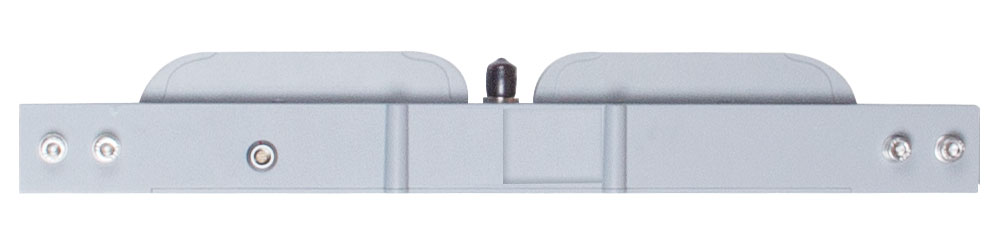
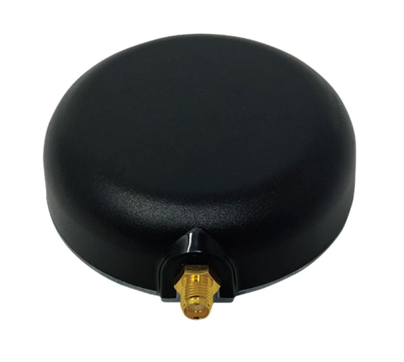
Tallysman’s custom XF filtering has been tested to mitigate new (Europe and Japan) and existing LTE signals, enabling the XF antennas to produce clean and pure GNSS radio frequency data.
Image: Tallysman Wireless
The TW7972XF surface mount Accutenna antenna has a metal base and robust IP67 military-grade radome. Attachment methods include screws, adhesive tape, and magnet mount.
Many antenna connectors and cable options are available.
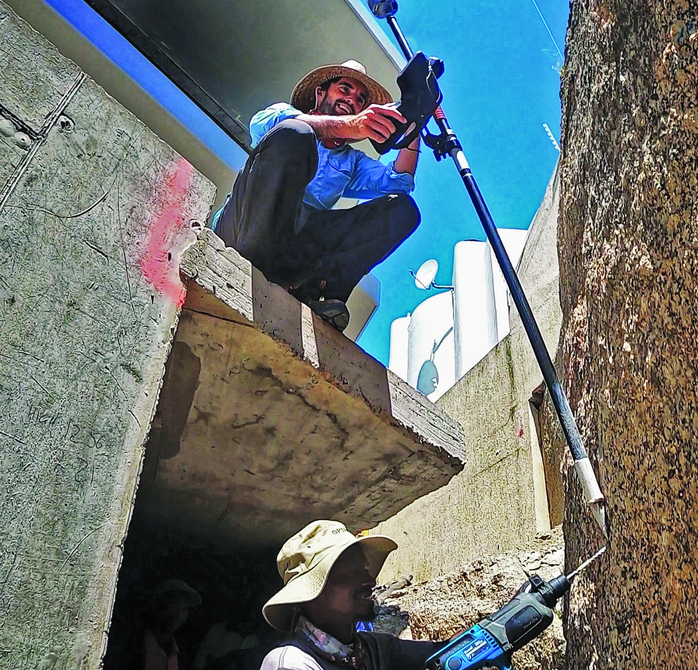
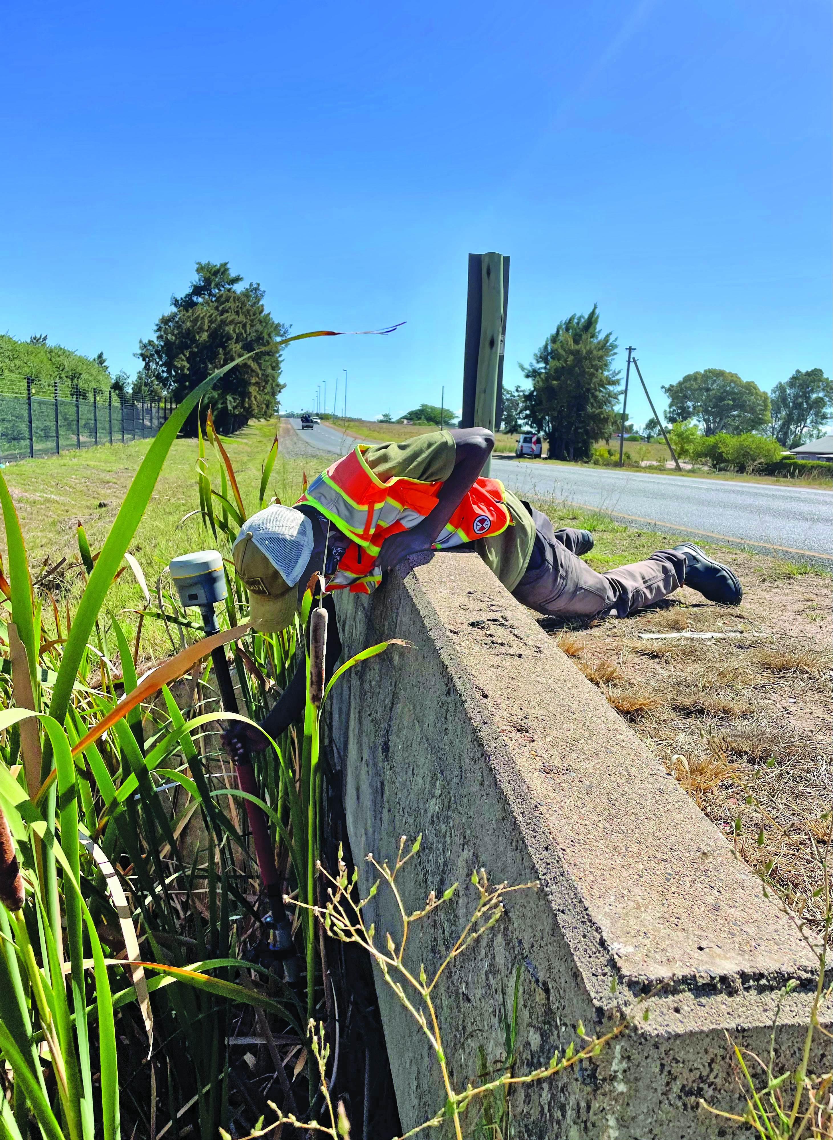
For tough shots in complex construction sites, Lee Landman says that tilt make impossible shots possible. (Image: Lee Landman)
Prior to the advent of tilt compensation for surveying and construction GNSS rovers, there were incremental approaches to tilt, with limited success. However, five years ago, “no-calibration tilt compensation” was first incorporated as a standard option for rovers. Some users remain skeptical or exercise the same caution as they did when such innovations as EDMs were first introduced. Nevertheless, the adoption of tilt compensation — for appropriate tasks — has spread rapidly. How did we get to this point?
For centuries, plumb bobs and bubbles were the only viable options to level an instrument or pole about a point. Early references to spirit levels appeared in the 15th century; however, siphon style water levels may have been in use in ancient Greece, China, and elsewhere for much longer. In more recent centuries, various types of level vials became a standard feature for surveying transits, theodolites and levels. Vials with a slight upward curve position a bubble between defined center marks when level.
Circular, convex glass bubbles appeared for industrial applications in the 19th century and were soon incorporated into surveying instruments and survey poles. In recent decades, electronic bubbles, or “e-bubbles” emerged, using microelectromechanical (MEMS) tilt sensors along with various methods to apply an orientation to compute the position of the pole tip relative to the phase center of the GNSS antenna. This is in contrast to relying on a bubble alone to orient the phase center directly above the pole tip.
There are both pitfalls and potential productivity losses if the pole has to be leveled solely with a bubble for each measurement; we’ll examine these later. If freed from the bubble — as electronic bubbles, tilt sensors, and various methods for orientation enable — how much productivity gain can be realized? For which tasks do the users find tilt compensation most useful? For which do they not? We talked with manufacturers, dealers and field users to find out.
Early adopters
Tilt for safer surveying. (Image: Lee Landman)
Lee Landman owns a firm in the Cape Town area of South Africa that provides construction layout, civil engineering layout and related topographic mapping services. Landman obtained a Trimble R12i GNSS rover, with no-calibration tilt, shortly after its release in 2020.
“Tilt is my go-to tool for almost all tasks now, except layout that needs better than 15 mm to 20 mm tolerance,” Landman said. “For topographic mapping, I will get everything possible with tilt, and then use a total station to get the points I can’t with the rover.”
Landman reports productivity gains of 30% to 50% on certain jobs. His crews will try to leverage a tilt rover for as much of a job as they can, provided it meets precision needs. For checking work, such as grade checking or layout verification, they will try to use tilt for everything first. Then in any areas that look suspect, they will set up a total station to confirm. He said this saves a lot of time up front.
After several years of use, Landman said there are specific tasks where they will not use tilt, and we find this echoed by other users interviewed (and from my own tests). For instance, construction layout of such structures as walls and columns where a consistent 5 mm to 10 mm tolerance is required. He said the same applies for tasks where precise elevation is key, such as on road curbs and final road levels. However, he noted: “That’s a GNSS precision thing, not a tilt issue.”
Landman provides other caveats,“I am nervous using tilt on long rods or when you constantly change rod height, as the results of using a wrong rod height would be disastrous, and the deflection on long rods could also degrade the results.”
Summarizing the overall impact on his operations, Landman explained, “We have become more competitive. Not by sharpening our price, but by the fact that using tilt is less fatiguing and faster to do layout and data collection. That gives us an edge over firms that are not using it.” He provided the example of a foundation layout that needed 300-400 points laid out and chalked in an hour or two so that the excavators that were standing by could start digging as soon as possible. “It normally takes two to three moves of the pole and bubble checks to get a point on position without tilt,” Landman said. “Now, when you are doing 300 points, that is 600-900 times that I don’t have to look at the bubble and adjust the rod. The amount of energy and fatigue that saves is just outstanding. No sore lat muscles and eye fatigue.”
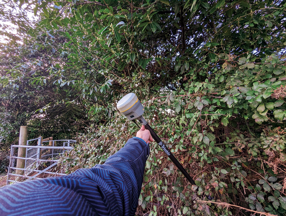
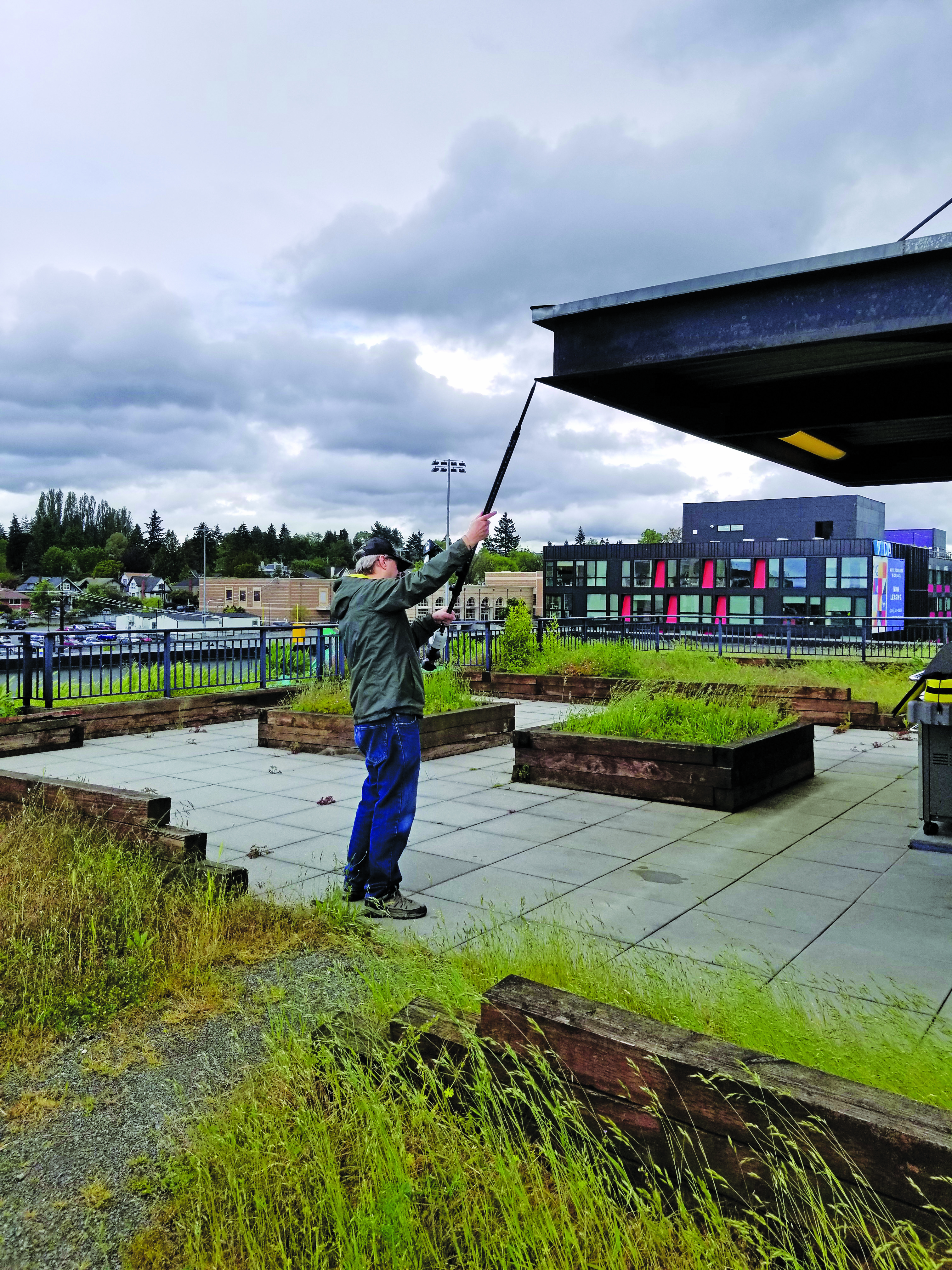
In the southwest of England, where Benchmark Surveys operates, fields and roadways are often lined with thick brambles, making if difficult to shoot features underneath them, such as utilities. James Richards of Benchmark says tilt has revolutionized the way they survey, enabling shots in places where even a total station (where the rod needs to be plumb) cannot take them. (Image: Benchmark Surveys)
Then there are shots that you cannot get with a bubble plumbed pole, Landman said. For instance, in checking rebar layouts prior to construction, as well as marking out on or below the steel rebar cages for plumbing points, voids and slab penetrations.
“Previously we could not easily do this, as you cannot get the pole plumb for total station shots or GNSS to place or check a point,” Landman said. “You just have to check positions on the steel for a column or wall to see if it has enough concrete cover or is in the right position prior to pouring concrete.”
James Richards is the survey manager for Benchmark Surveys, a family-owned and operated firm in the southwest of the UK that has steadily grown its portfolio of services. In part, this growth has resulted from their willingness to embrace new and emerging technologies. This included adding tilt compensated R12i rovers to their instrument inventory shortly after they became commercially available.
“We use tilt on every surveying task where we can use GNSS,” Richards said. “Tilt has enabled us to complete numerous jobs where we would have otherwise only been able to use a total station.” Apart from control, there are not many tasks for which Richards would not recommend using tilt, “It has helped improve our surveys. We can capture data quicker and easier than before and with greater accuracy.” Examples of daily challenges his crews face include getting shots in and around ditches, field boundaries, and boundary fences in foliage, and walls with foliage overhang. These are now easily captured using tilt.
“Tilt has had an enormous impact on our business. We complete work to a higher standard, capturing data quicker and easier,” said Richards. “It helps us capture data that was not possible without offsets. We’ve seen a rise in profitability since using tilt. Surveyors seem to be happier with day-to-day work, knowing that they can capture the data required to meet our high standards, and clients are also happier when receiving more data than expected from surveys.”
Stages of adoption
CHC Navigation is a GNSS developer and manufacturer that has sold hundreds of thousands of units over the past 15 years. They were quick to develop and implement tilt compensation technology, which has now become standard on all of their current models.
Rachel Wang, product manager of CHC Navigation’s Surveying and Engineering division explained the four stages they undertook in developing tilt.
“In the first stage,” said Wang, “users had to rely on the survey pole’s bubble to maintain a centered state, which had significant limitations in terms of measurement accuracy and accessibility.”
In addition to any GNSS error, there could be additional error due to a poorly calibrated bubble, a pole that is not straight, misalignments with each joint of telescoping rods, and user error in trying to keep the bubble lined up while simultaneously operating the field collector (if not using a bipod). Often it seemed that a surveyor would need extra hands and an extra set of eyes.
“The second stage introduced the first generation of tilt compensation using an electronic compass,” said Wang. “Although this technology enabled the first tilt measurements, it was hampered by problems such as low accuracy, tedious calibration, poor reliability, and susceptibility to interference from electrical currents or magnetic fields.”
Common applications for tilt features include getting shots up against structures and improving sky view. For example, for this bridge column with sky partially obstructed by the bridge deck. (Image: CHCNAV)
Such magnetic oriented tilt compensation had been implemented on rovers several years prior to no-calibration methods, by manufacturers that included Javad, Trimble, Topcon, and others. The calibration step often involved rotating the rover vertically in eight or more horizontal positions. This was cumbersome, and the orientation quality changed over time, mostly unbeknownst to the user. It was no surprise that “mag tilt” never really caught on, and unfortunately it made some users wary of tilt in general, even when no-calibration solutions came along.
“The third step was the development of the second generation of tilt compensation, using hybrid positioning based on GNSS + IMU,” Wang said. “This technology was less affected by magnetic interference, but still required initialization of the IMU by shaking the survey pole.” I had tried several models from manufacturers of early “minimal calibration tilt” enabled rovers. For each, a certain amount of movement had to be induced on the pole, by walking around a bit, swinging the pole back and forth, or in a circular sweep. It often did not take more than a minute or so, and then normal moving around on the site would usually keep it calibrated. This was a tremendous step up compared to the old “mag tilt.”
“More recently, we are proud to announce the fourth step in our tilt measurement technology integrated into our new i93 GNSS RTK rover,” Wang said. “Our Auto-IMU technology further simplifies the IMU initialization process by observing acceleration at some point between startup and RTK operation. This replaces the previous repeated shaking of the survey pole for initialization. In fact, users can initialize the IMU while walking or moving normally. In addition, once initialized, the IMU feature is not easily lost even if the pole is carried on the shoulder, held horizontally, or even upside down.”
Wang said that all current CHC survey rovers are equipped with their newest tilt compensation technology. Since the international launch of their first CHCNAV GNSS RTK with IMU, the i90 GNSS in 2019, they have continued to incorporate this feature into all subsequent GNSS rovers. “Based on feedback from users, we know how valuable this feature is,” said Wang. “That is why we have made tilt compensation a standard feature on our current i73, i83, i90 and i93 models.”
Uptake
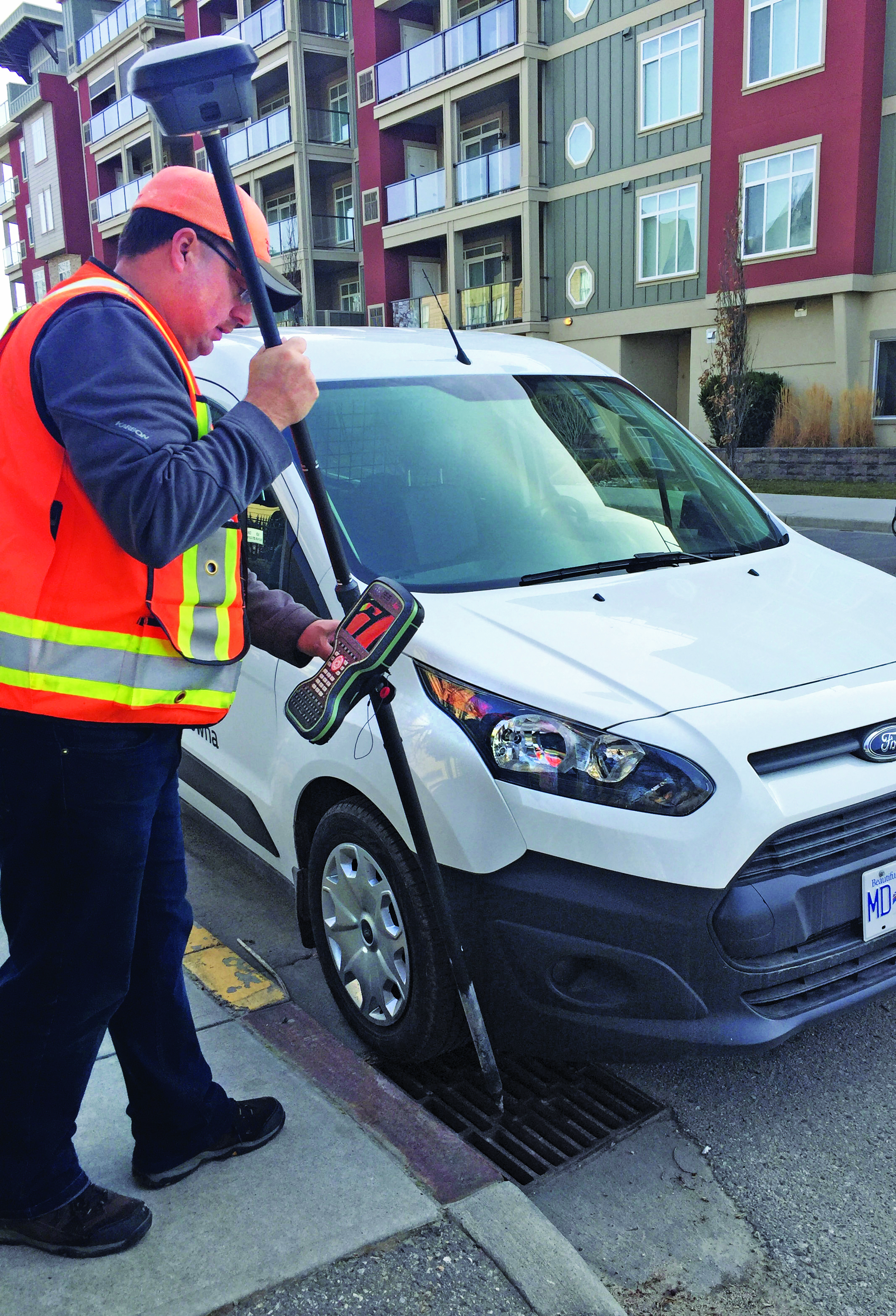
Greg Maier of the City of Kelowna, Canada, was an early adopter of tilt. He found it invaluable to access hard to reach features, such as this inlet under a car, and for safer surveying along the edges of roadways. (Image: Greg Maier)
For the past year, I’ve been talking to other GNSS manufacturers, their dealers, and customers, together with monitoring the subject in surveying and construction groups and forums online. Manufacturers have reported overwhelmingly positive feedback from dealers and customers about the tilt function. Typical feedback focuses on convenience and time savings of not having to level the pole manually.
“Based on our research, we have found this feature to be extremely useful for surveying and staking out on construction sites,” Wang said. “It has increased speed and efficiency by up to 30%.” I have heard similar statistics from each of the manufacturers contacted, as well as their dealers, and most of their customers that have used tilt.
There are common threads to much of the feedback from various sources: the tilt function is now an indispensable tool for many surveying applications.
As Wang noted, “While some users still prefer to use the traditional bubble to plumb the pole, we have seen a clear trend toward adoption of the tilt function in the field. The benefits of tilt, such as faster and easier surveying, are becoming more apparent to our users. As we continue to improve the accuracy of our tilt-compensation, we expect that more and more users will choose this convenient feature over other traditional GNSS rovers in the future.”
Another common observation (no pun intended): even if the pole-tilt feature offers significant convenience and time-saving benefits, it may not be the best option for tasks that require very high accuracy, such as surveying control points. For such tasks, manufacturers, dealers, and users recommend using the traditional bubble on a pole with a bi-pod mount for more accurate measurement.
As something completely new, the uptake across the surveying profession and for construction took time to grow. “It took quite a while to catch on here,” said Keith
Belsham, branch manager for Spatial Technologies, a measurement solutions dealer in the Vancouver region of British Columbia Canada. They specialize in solutions from Leica Geosystems and were an early provider of the Leica GS18 T, widely recognized as the first GNSS rover with no-calibration tilt.
“My perception is that in the United States and some other countries, there are more companies trying to stay at the top of technology,” Belsham said. “However, in our region surveyors are very cautious and need to do a lot of checks and look to see how others respond before they consider it. It was that way with other new technologies; I have memories of numerous total station demonstrations, when prism-less EDM’s were first coming out, where surveyors would pull out a tape measure to check whether the instrument was giving the correct distance.”
About three years after the introduction of no-calibration tilt is when Belsham said it really took off in his region, and it is now quite popular. He gave an example of a customer buying a Leica GS16 (no tilt), saying that they did not see a need for tilt, considering the extra expense. They then upgraded a week later once they were in the field and recognized many instances where the tilt would have saved them time.
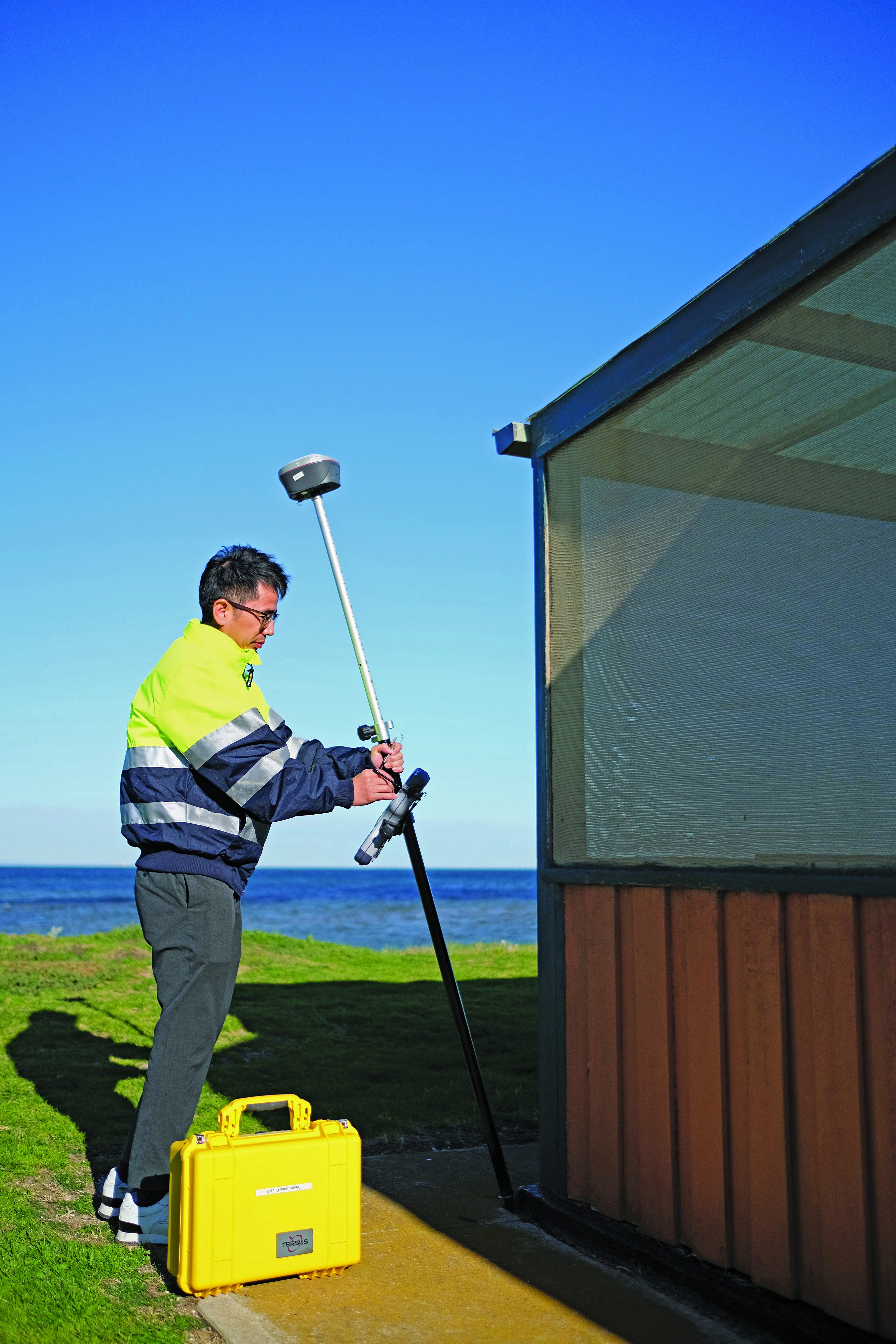
Rather than go the OEM route, Tersus GNSS developed its own GNSS board, positioning engines, and IMU tilt integration. (Image: Tersus GNSS)
A Spatial Technologies customer that has found tilt useful for numerous applications is Lucas Geomatics, a surveying firm based in Surrey B.C. “When I set up GNSS units for construction companies, tilt is great as they don’t have to be super accurate,” said Peter Smith. “I mean, here’s a machine with a bucket that’s 3 f wide, and the bucket is about an inch thick. The grade checked does not have to be super accurate for the machine to hit it, because end users in construction companies do not have to do precise surveying. They’re great guys who dig trenches and tilt gives them more than enough precision for their needs.”
Among the many uses Smith has found for tilt, he has also adapted it in a very creative way to deal with areas of deep foliage. A common approach to working in thick foliage is to raise the GNSS rover up on a tall or extended pole; this can increase the number of satellites viewed and reduce multipath. However, working with a bubble low enough on the pole to see makes it quite difficult to keep the rover at the top sufficiently still and plumbed over the tip. I remember some clever (albeit questionable) solutions folks cobbled together to help plumb very tall poles, such as a small live video camera pointing down over a bubble near the top of the pole to view on a phone. Smith said that tilt solved this problem, and he uses various tall rods, including one that extends to as much as 12 m. He chose a non-conducting pole, such as those used by utility companies for high foliage.
He does prefer to use the rover on a bipod, though, and bubble for control and points requiring very high precision. He sets the data collector software to log positions at 5 Hz or 10 Hz (standard in most systems) and has the software average multiple positions over the course of a minute or more.
Smith said that tilt has made a lot of difference in their surveys, especially where they want a lot of productivity, but do not need very high precision. Part of why he is impressed with the GS18 T is that they had upgraded from an older system, that only used two constellations, to full constellation support on their new rover.
Stability through motion
It sounds counter to one of the key principles for surveying measurement: the instrument and pole must be kept very still. However, in other data collection technologies, including aerial mapping and mobile mapping, leveraging predictable motion, acceleration, and trajectory caught on decades ago. There are numerous integrated GNSS + IMU solutions from, for instance, Applanix and NovAtel, that are the key positioning components for kinematic mapping systems. Such integrated sensor solutions are also in broad use now for UAV real-time and post-processing workflows.
One challenge for integration into survey rovers, was miniaturization. Additionally, such solutions needed a wealth of satellites and signals to be usable at tilted angles. The Galileo and BeiDou constellations reached full complement at about the same time as no-calibration tilt was introduced. Some manufacturers even integrated new antenna designs to better utilize satellites at tilted angles, for example in the Leica GS18 T.
The electronic bubble aspect of such solutions was in some ways the easiest to achieve. Depending on the quality of components, multiple tilt sensors can measure the angle of tilt at precisions matching, or even bettering that of typical pole bubbles. Plus, they are built into the rover boards with a direct relationship to the axis and phase center, whereas the bubble is external, down on the pole.
Integrated IMUs, with as many as nine axes, are highly sensitive, as are accelerometers (if an integration utilizes those). Skeptics always point out that IMUs are subject to drifting over time. However, the observed high-rate GNSS positions and motion sensors are continuously updating the calibration of the IMU. It is true of no-calibration tilt systems that if you hold the pole still too long, it will lose its calibration. Or if you move it too fast. Though on every tilt rover I’ve tried, I moved it around vigorously and spun it (more than would happen in normal operations) and it still kept its calibration. There can also be instances of environments with excessive multipath hazards — such as heavily wooded areas, urban canyons, or congested construction sites — where users often find it best to turn off the tilt for certain shots.
Industry penetration
Tilt for shooting inverts. (Image: Lee Landman)
While manufacturers have approached the GNSS/IMU solution in varied ways, the fundamentals are the same. Once some of the major vendors developed and integrated tilt, they began offering this feature for OEM customers, and in recent years we see tilt on many other brands worldwide. There are relatively new players in the market that took a different approach, developing not only their own GNSS boards and positioning engines, but IMU solutions as well.
Tersus GNSS has rapidly gained a presence in various global markets, though relatively new in North America. While starting as an OEM, the company pivoted to developing its own boards in 2015, and GNSS + IMU integrations more recently. It recently published a paper about what they call its “Extreme RTK Solution” that has a section with data from their own tests for both plumbed and tilted observations.
I did some quick tests with a Tersus Oscar Ultimate, at various angles of tilt, and in mixed environments. The results aligned closely with those in the paper, as did tests with other tilt rovers. I have had the opportunity to try rovers of several different brands, to check precision at various tilt angles against points established with static observations (to see how much the tilt added to the total error). While these were not comprehensive tests, I did compare notes with surveyors who did their own tests, and we’ve all been finding out the practical limits of tilt. Perhaps part of why tilt took a while to catch on was that surveyors needed some time with these units in real-world environments, to get a feel for sweet spots for tilt for different tasks that have specified error budgets.
To get an idea of potential productivity gains, I did a small topographic survey of an area I had previously surveyed with a conventional rover, total station, and scanner. The total station and tilt-less GNSS took about the same amount of time — but with tilt it took about half the time. Many variables can and do come into play, but the figure I keep hearing of up to 30% efficiency gain for many applications seems realistic. Certainly, for asset and resource mapping, tilt could easily fit the looser precision requirements.
As for degradation at various angles of tilt, checks against static points (beyond standard GNSS error) showed negligible differences under 5°, 1 cm up to 15°, 2 cm or more around 45°, and 3 cm or more at 60°. This was just a cursory look, and indeed any surveyors that use tilt should do their own testing. I did notice in the data that when doing simple topo shots, just moving around the site, the pole did not often exceed 5°. Therefore, moving around quickly and efficiently for topo, not having to look at the bubble, improves productivity without significantly compromising quality.
Layout, as surveyors and construction folks who use tilt say, can be quite a snap compared to the old “plumb-shoot, move-plumb-shoot, move-again-plumb-shoot, etc.,” process. You simply move the tip of the pole around until you are on the point.
Enabling further sensor integration
Tilt compensation has now extended to non-GNSS tech, for instance Leica Geosystems AP20 prism poles (used with robotic total stations). (Image: Gavin Schrock)
No-calibration tilt, and multi-constellation GNSS, have enabled further developments that may not have been practical otherwise. Leica has since added an image point extraction feature to its GS18I. This marries the tilt and a camera with a clear path to processing the images in the data collector software. With tilt running, and at ranges under 6 meters, you can roughly aim the camera side of the rover toward say, features under an overhang, that you would not otherwise be able to shoot with a GNSS alone. You walk past the features as the camera takes a series of images. Then, in the software, you identify the points in multiple images and photogrammetrically it gives the offset. You can also process the image series into point clouds. There were several attempts at this sort of solution in the past by various brands. However, without tilt it was too cumbersome as you would need to stop and plum for each image in the series. As one user told me, the new image point features are “like having a UAV on a pole.”
Tersus GNSS has taken a slightly different approach to their image point solution. You pick the point you desire in the camera view on the data collector, and then move along as the software automatically identifies the same point in subsequent frames, until it has enough matches from multiple angles to calculate the offset. CHC Navigation has just announced its own image point feature, with a two-camera integration in the i93 Visual GNSS RTK rover.
Pole tilt also has been integrated into non-GNSS solutions. For instance, the recent release of a prism-pole tilt solution by Leica, the AP20. A constant stream of positions of the prism, from the total station, takes the place of GNSS in this application. They’ve also included a rather clever automated pole-height feature.
What could be next? Perhaps small solid state lidars on rovers, or combined lidar/camera solutions such as on an iPhone/iPad, or a tiny SLAM scanner (that could also aid in position stabilization)? Not to mention what might be coming in the not-too-distant future in the realm of quantum sensing.
In considering all feedback about no-calibration tilt, it seems it is very much here and here to stay. There are many who love it and try to use it for everything (perhaps, in some cases, too many tasks). For others, it is conditional love: use where appropriate. While others still hate it immediately, perhaps on principle, though I find those folks typically have never tried it. Legacy tools and methods provide comfort and known levels of risk. New features such as tilt, provided some time is spent gauging its performance and appropriateness for various tasks, can deliver productivity gains that should prompt reevaluation of some long-held assumptions.
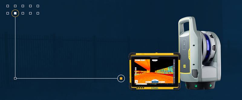
Trimble has released the X9 3D laser scanning system — a versatile reality capture solution suitable for surveying, construction and engineering users. The X9 is designed to enhance performance in more environments while leveraging Trimble’s X-Drive technology for automatic instrument calibration, survey-grade self-leveling and laser pointer for georeferencing.
The X9 expands on Trimble’s X7, delivering longer range, higher accuracy, shorter scan times and sensitivity, improving scan results. Advanced processing and a high-performance laser increase the sensitivity of all scans, enabling the X9 to capture difficult dark or reflective surfaces. A new center unit design also improves signal transmission for better scan quality.
The X9 provides accurate and dependable data, enabling confident decision making both in the field and in the office through in-field registration with Trimble Perspective and FieldLink software by minimizing the need for target deployment. The auto-calibration eliminates the need for annual calibration.
In addition, the X9 includes survey-grade self-leveling with the industry’s widest compensation range for fast, easy setup.
The X9 data can be delivered directly from the Perspective or FieldLink software to Trimble’s office software — including the Realworks 3D scanning software — business center office software, SketchUp and Tekla, or exported to industry-standard formats to produce application-specific deliverables.
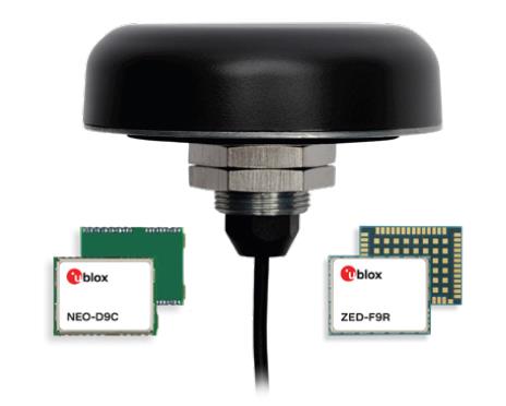
Tallysman Wireless and u-blox have partnered to develop PointPerfect precise point positioning real-time kinematic augmented smart antennas.
The ZED-F9R high precision GNSS and the NEO-D9S L-band receivers from u-blox have been integrated with Tallysman’s technology. The product integration will provide accuracy and precision.
The multi-band (L1/L2 or L1/L5) architecture removes ionospheric errors, and the multi-stage enhanced XF filtering improves noise immunity while relying on the dual-feed Tallysman Accutenna element to mitigate multi-path signal interference rejection. Some versions of the new smart antenna solutions include an inertial measurement unit (dead reckoning) and an integrated L-band corrections receiver to ensure operation beyond terrestrial network reach.
The PointPerfect GNSS augmentation service is now available in North America, Europe and parts of Asia Pacific.