Tag: 0126

  • Launchpad: Delivery drones, scanners, lidar and more

    Launchpad: Delivery drones, scanners, lidar and more

    A roundup of recent products in the GNSS and inertial positioning industry from the January-February 2026 issue of GPS World magazine.

    Autonomous

    1. Delivery Drones 

    Volatus deploys medical supplies in Canada 

    IMAGE: TRIMBLE
    Image: Trimble

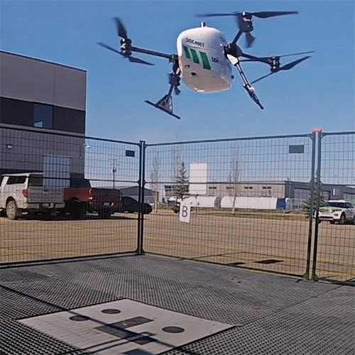
    Volatus Aerospace has integrated the Trimble PX-1 RTX solution into its commercial delivery drone service to achieve accurate and robust positioning and heading. The Trimble module provides Volatus’ clients with a turnkey solution for highly accurate aerial data acquisition and fully remote drone operations in real-world missions, including beyond visual line of sight (BVLOS). The PX-1 RTX uses Trimble’s CenterPoint RTX corrections along with compact, high-performance GNSS-inertial hardware to deliver real-time, centimeter-level positioning and highly precise inertial-derived true heading measurements. This technology reduces operational risks associated with poor sensor performance or magnetic interference by providing enhanced positioning redundancy.

    Volatus Aerospace, Trimble

    2. Defense Drone

    For border protection and long-range surveillance missions 

    IMAGE: COPTERPIX
    Image: CopterPIX

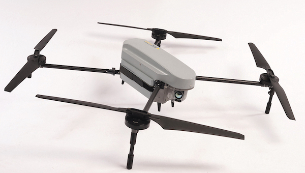
    The ERE95 Mini by CopterPIX operational platform is fully capable of GNSS-denied missions and integrates a long-range, anti-jamming communication system supporting distances of more than 20 km. It has an endurance of 2 hours and can carry up to 5 kg of payload for up to 1 hour. It also has integrated daylight and thermal imaging for advanced surveillance. With a fully foldable frame, the platform collapses into a backpack-sized kit, making it suitable for rapid mobility and field operations. Its modular “puzzle” architecture allows quick adaptation of SDR modules, optical payloads, and navigation solutions, enabling mission-specific configurations. To support rapid field deployment, the ERE95 Mini features a mechanical and electrical quick-connect interface, allowing operators to switch payloads in seconds and maintain continuous operational readiness across all missions.

    CopterPIX

    3. Visual Navigation

    Integrated into long-endurance unmanned aircraft system 

    Puma LE gains GNSS-denied navigation with the VNS kit, ensuring precise, resilient flight and mission continuity in contested environments. (Image: AeroVironment)
    Image: AeroVironment

    AeroVironment has integrated its visual navigation system (VNS) kit with the Puma Long Endurance (LE) small unmanned aircraft system, delivering GNSS-denied navigation capability. The VNS kit uses advanced computer vision and onboard processing to deliver precise, GNSS-independent navigation. Using a suite of downward-facing sensors, cameras and onboard computing, the VNS kit performs visual inertial odometry to capture and analyze terrain imagery, estimating true aircraft position in real time. The system fuses continuous visual data from the cameras with motion inputs from onboard inertial sensors to calculate precise position, velocity and orientation — allowing the aircraft to know where it is and where it is going when GNSS is not available. It automatically transitions between GNSS-enabled and GNSS-denied modes with zero pilot input, ensuring uninterrupted mission continuity in contested environments.

    AeroVironment

    4. Counter-Drone Radar

    Low power, small footprint setup for close-airspace awareness 

    Photo: MatrixSpace
    Photo: MatrixSpace

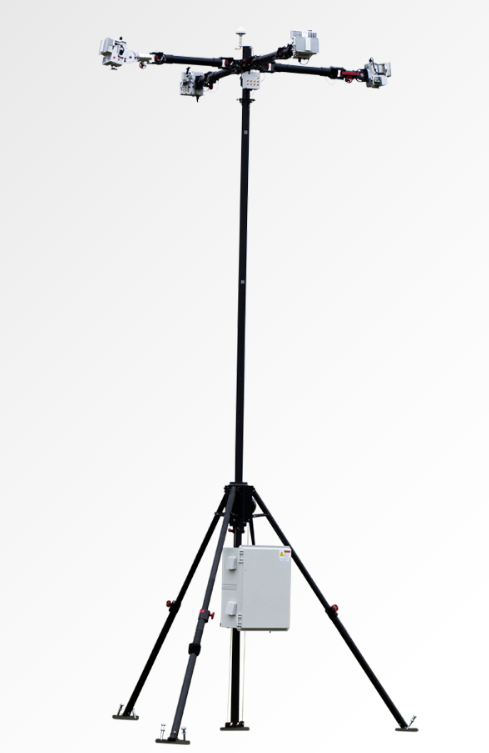
    The Portable 360 Radar is a rugged, easily transportable radar kit that delivers reliable close-airspace awareness with panoramic coverage for rapid-response counter-drone operations, from safeguarding stadiums and large public gatherings to border security and battlespaces. The MatrixSpace platform unifies threat awareness across multiple networked Portable 360 Radar systems and other sensors, without compromising local operation. By combining AI edge processing with MatrixSpace AiCloud Enterprise software, central command centers get an enhanced common operating picture and deep airspace activity analytics to assure public safety.

    MatrixSpace

    Surveying and Mapping

    1. Laser RTK Receiver 

    Reliable in complex and GNSS-limited environments

    Photo: SatLab
    Photo: SatLab

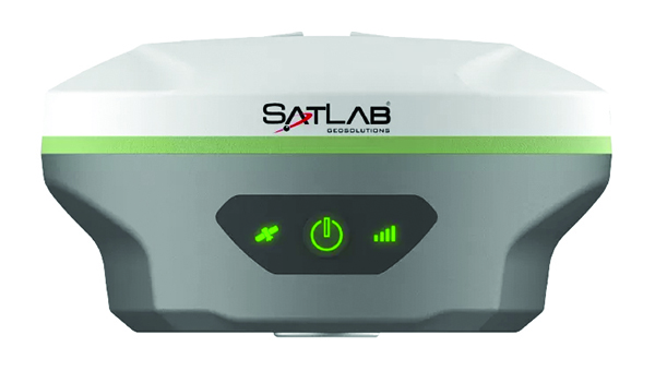
    The SatLab SL8 Laser RTK GNSS receiver combines dual cameras, GNSS, an IMU and visible laser technology to make surveying faster and easier. With non-contact measurement, image-assisted targeting, CAD live-view stakeout, and a built-in LoRa radio. It ensures smooth, reliable work even in complex or GNSS-limited environments. The SL8 achieves 2 cm accuracy within 10 meters and enables efficient data collection across bridges, tunnels, riverbanks, and other sites where traditional GNSS methods are restricted. It features image-assisted targeting through SatSurv software, displaying laser points directly on real-time images for quick and precise aiming. Its automotive-grade IMU requires no manual calibration or initialization and enhances measurement accuracy by up to 40% in GNSS-challenged areas. A built-in multi-protocol LoRa transceiver provides stable transmission beyond 15 km and compatibility with multiple RTK brands. The integrated CAD and visual stakeout functions combine live imagery with CAD data, allowing users to visualize target points on site and increase layout efficiency by up to 50%.

    SatLab Geosolutions

    2. Utility Mapping 

    Partnership aims to provide precise maps

    Image: Getty Images / iStock / SummerParadive
    Image: Getty Images / iStock / SummerParadive

    A complete precision mapping solution for the utility and critical infrastructure industries worldwide is the goal of a partnership between ProStar Holdings and Tersus GNSS. The partnership will integrate Tersus’s survey-grade GNSS receivers with ProStar’s PointMan Underground Utility Mapping Software, providing an affordable, field-ready solution. The partnership will use ProStar’s LinQD open API integration platform, which is designed to enable seamless interoperability between emerging technologies and legacy systems, creating a robust global ecosystem for geospatial intelligence, uniting equipment manufacturers and service providers under the initiative.

    ProStar Holdings, Tersus GNSS

    3. Handheld Scanner 

    Designed for mobile mapping and reality capture

    The MVP S1 mobile mapper features an Al-driven RTK-SLAM algorithm that fuses lidar, vision and GNSS data. (Image: Tersus GNSS)
    (Image: Tersus GNSS)

    The MVP S1 RTK-SLAM handheld 3D laser scanner uses GNSS through an AI-driven RTK-SLAM workflow, as well as lidar data with imagery from dual 48-megapixel panoramic cameras. The combination provides survey-grade results in both GNSS-denied and open environments. The system achieves centimeter-level accuracy outdoors and maintains performance indoors or underground through SLAM processing. TimeSync 3.0 synchronizes the hardware, aligning sensor data at the microsecond level and supporting consistent datasets and reliable post-processing. A mobile application provides users with real-time feedback, including previews of colorized point clouds while scanning, as well as basic scan reports on site. This feature helps operators verify data completeness and quality before leaving the field, reducing the need for repeat visits. The MVP S1 supports 3D gaussian splatting (3DGS), enabling creation of textured, photorealistic 3D models. This capability is useful for building information modeling, construction progress monitoring, underground surveys, forestry analysis and industrial site documentation.

    Tersus GNSS

    4. GPR Systems for UAVs 

    Enable extended subsurface mapping

    The MALÅ GeoDrone 600 radar package. (Photo: SPH Engineering)
    (Photo: SPH Engineering)

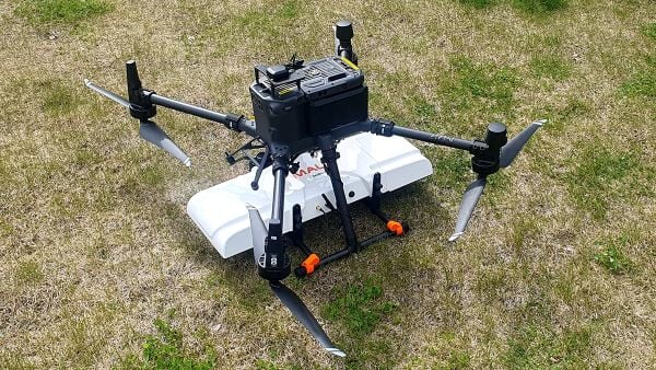
    The MALÅ GeoDrone 600 and Zond Aero 600 NG are two new high-resolution ground-penetrating radar (GPR) systems for UAVs. They significantly enhance high-resolution subsurface investigations with drones, supporting applications in engineering surveys, utility mapping, archaeology, environmental studies and geophysical research. They enable surveyors to capture consistent, high-quality subsurface data in areas difficult, slow or unsafe to access with traditional ground instruments. Operating at 600 MHz, the antennas offer a balance between penetration depth and fine near-surface resolution. Typical penetration from the drone is up to 2 meters, depending on surface conditions, while SPH Engineering’s True Terrain Following ensures stable antenna height to maintain data quality and repeatability.

    SPH Engineering

    5. Visual RTK System

    For high-precision surveying, photo surveys and 3D modeling

    Image: Aurora Navigation
    Image: Aurora Navigation

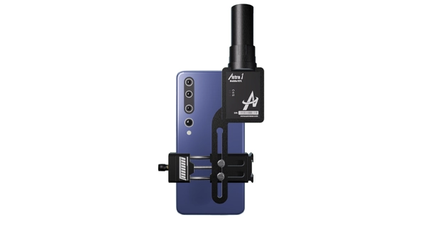
    The Astra1 Mobile Visual RTK is a professional-grade GNSS receiver engineered to redefine high-precision mobile data acquisition. It is built to meet the demand for highly portable, reliable, high-precision tools that simplify complex field operations. At 60 grams, the Astra1 is an ultra-compact solution designed to deliver reliable, centimeter-level positioning and advanced 3D mapping capabilities through seamless integration with a smartphone and the proprietary Anypos App. Accuracy is RTK 8mm+1PPM horizontally, 15mm+1PPM vertically, photo survey <4 cm (2-15 m distance). The Astra1 allows users to capture photos with precise RTK coordinates, enabling the creation of accurate 3D models for detailed construction verification and digital twinning applications. 

    Aurora Navigation

    Transportation

    1. 5G Cellular Module

    Automotive-grade module integrates dual-band GNSS

    The AR588MA is a 5G-advanced (5G-A) automotive-grade cellular module that integrates dual-band GNSS supporting both L1 and L5 bands with up to 30 Hz output. Based on MediaTek’s latest-generation MT2739 platform, the AR588MA supports 5G-A communication technology and complies with the 3GPP R18 standard protocol. It features both NB-NTN and NR-NTN satellite communication capabilities and supports dual-SIM dual-active (DSDA) technology, offering improved stability and reliability on cellular connections. It also includes intelligent driving scenario recognition. Designed in compliance with the AEC-Q104 Grade 2 automotive standard, it delivers fast, stable connectivity and reliable security for in-vehicle communication and benefits on-roof applications, such as smart antennas for automotive, with higher-temperature support.

    Quectel Wireless Solutions

    2. Heave Accuracy

    IMU upgrade accounts for maritime wave motion

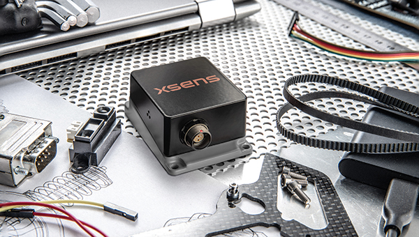
    A firmware upgrade to the Xsens Sirius and Xsens Avior IMUs delivers centimeter-level vertical displacement measurements for marine stabilization and control systems. The new Heave feature enables real-time stabilization and wave compensation in a wide range of marine applications. Marine engineers can access comprehensive motion data — roll, pitch, yaw and heave — from a single compact sensor, eliminating the need for external processing or oversized tactical-grade systems while maintaining the precision required for offshore platforms, vessels, docking systems, marine robots, buoys and surveying equipment.

    Xsens

    3. Lidar with Camera

    Compact module reduces OEM integration complexity

    Image: Innoviz
    Image: Innoviz

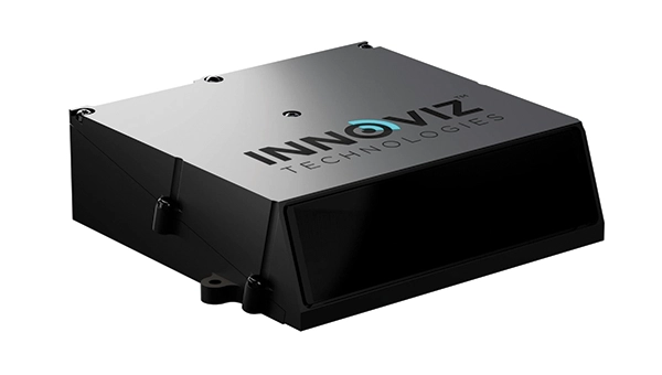
    The InnovizThree is fully colored long-range lidar with camera that creates a compact sensor-fusion module designed to reduce OEM integration complexity. The solution combines lidar and RGB sensing in a single compact perception module, purpose-built for behind-the-windshield installations, drones, micro-robotics and humanoids. The consolidation of an RGB camera inside InnovizThree reinforces Innoviz’s commitment to scalable, OEM-friendly sensor-fusion perception solutions designed for series production and long-term deployment, with the potential to enable faster deployment and cost savings. The RGB sensing capabilities are factory-aligned with the lidar, enabling precise and consistent visual-to-lidar geometry across production units. This alignment, combined with hardware-synchronized capture, will enable reliable multi-modal sensor-fusion data correlation while reducing calibration effort during vehicle integration.

    Innoviz Technologies

    4. AGX Platform

    High-integrity GNSS integration for autonomous driving

    Image: Getty Images / iStock / FlashMovie
    Image: Getty Images / iStock / FlashMovie

    Swift Navigation is collaborating with Nvidia to enable a scalable, cost-effective approach to autonomous driving by integrating the Nvidia Drive AGX platform with Swift’s globally referenced, centimeter-accurate GNSS positioning. Swift Navigation offloads absolute localization to the GNSS sensor stack using its Swift Automotive Suite. The suite is a complete, modular software solution for safe, high-integrity precise vehicle localization that combines the centimeter-level Skylark Precise Positioning Service with the Starling positioning engine, software that fuses raw GNSS data and corrections with IMU and wheel odometry to deliver high-integrity, centimeter-accurate positioning (PVT). By using Swift’s high-precision stack for lane-level positioning, the vehicle’s optical sensors focus on obstacle detection and safety, lowering system cost and complexity.

    Swift Navigation

    5. 5G GNSS Antennas

    Suitable for fleet and rail applications

    Image: Sinclair Technologies
    Image: Sinclair Technologies

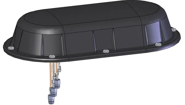
    Sinclair’s new SM 5G Family Tier features the SM714 and SM2601 series antennas. The multi-band, multi-port antennas are engineered to deliver superior connectivity, reliability and versatility for GNSS and other mission-critical wireless transportation applications. The SM714 is a 4-in-1 low-profile customizable transit antenna that combines 5G/LTE, Wi-Fi and tri-band GNSS coverage in a single compact form. Supporting 617–5925 MHz, it enables seamless operation across all major 5G and LTE bands. It is suitable for vehicles, fleet systems and connected mobility applications requiring a discreet, high-performance solution. The SM2601D is a 5-in-1 low-profile customizable antenna that features five independent ports: one for PTC (219–223 MHz), one for Wi-Fi (2400–6000 MHz), one for GNSS, and two full-band cellular ports (694–2700 MHz) that support diversity and MIMO operation for multi-radio systems. This dual-cell configuration offers greater throughput, flexibility, and redundancy in complex communication environments.

    Sinclair Technologies

    6. Lidar Platform

    High-precision depth sensing and real-time
    velocity measurement

    Image: Voyant Technology
    Image: Voyant Photonics

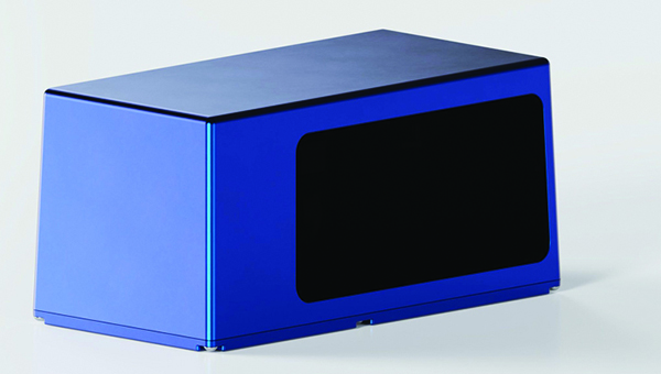
    New versions of the Carbon lidar platform add 32-line and 64-line variants for compact, cost-sensitive and compute-limited systems. The new models complement existing 128-line configurations and are optimized for industrial autonomy, robotics, drones and smart infrastructure applications. They offer lower data rates and simplified integration while maintaining core FMCW advantages including velocity measurement, interference immunity and high dynamic range. With line resolutions spanning 32, 64 and 128, original equipment manufacturers and system integrators can tailor performance, bandwidth and compute load to specific use cases, from robotics and automated guided vehicles to drones and embedded edge platforms. The Carbon family’s silicon-photonics architecture integrates beam steering and coherent detection on a single photonic chip. The new variants include high-precision depth sensing and real-time velocity measurement, exceptional ambient light immunity and compact design for industrial and mobile environments.

    Voyant Photonics

    7. Base Station

    For automotive track and varied environment testing

    Image: VBox
    Image: VBOX

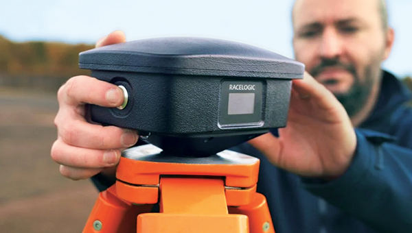
    The NTRIP Base Station from VBOX Automotive combines a multi-constellation, multi-frequency GNSS engine with a built-in networked transport of RTCM via internet protocol (NTRIP) server. The equipment transmits real-time kinematic corrections over radio and cellular or Wi-Fi networks, supporting accurate real-time positioning across wider areas in varied environments compared to traditional radio-only systems. The base station launches in three models, with specifications designed to fit users’ needs. All systems combine quad-constellation, dual-frequency GNSS technology with built-in cellular and Wi-Fi connectivity.  Compatible with VBOX 4, VBOX 3iS and external GNSS rovers, the new NTRIP Base Station supports both MSM4 and MSM7 RTCM formats, has up to 24 hours of battery life and is rated to IP67 to handle the demands of long outdoor test sessions. Models include Internal GNSS antenna and 2.4 GHz radio (quick to deploy for short-range applications, for temporary or mobile testing); Internal GNSS antenna, no radio (compact and simple, suitable for NTRIP or semi-permanent installations with external high-power radio masts); and External GNSS antenna, no radio (optimized for permanent installations with tripod-mounted antennas for maximum satellite visibility, supporting NTRIP or external radio).

    VBOX Automotive

  • Seen & Heard: Crust shifts, sinking plates and GNSS disruptions worldwide

    Seen & Heard: Crust shifts, sinking plates and GNSS disruptions worldwide

    What on Earth is happening?

    Image: NASA
    Image: NASA

    Several interesting things, according to geologists who study data from the global network of geodetic-quality receivers. A team at the University of the Basque Country found the Iberian Peninsula rotating clockwise as Africa closes on Eurasia by 0.2 inches per year (5 mm), near Gibraltar and the Alboran region. Meanwhile, in a process called lithospheric dripping, Earth’s crust is sinking under Central Turkey despite being part of a broader region that has been uplifting for millions of years, according to University of Toronto researchers. Meanwhile, in the U.S. Pacific Northwest, seismic data collected during a National Science Foundation study shows the Cascadia subduction zone actively breaking apart. 

    Making better robots with GNSS

    Image: Robosat Project
    Image: Robosat Project

    Autonomous robot navigation in the wild using satellite-based 3D geographical information (Robosat) aims to provide a scalable multi-GIS high-quality data collection platform through using a quadrupedal robot that can autonomously perform long-distance missions in challenging environments, such as the Alps or Finnish forests. Researchers from Finland, Switzerland, Spain and Romania gathered at Tampere University in Finland to share data, identify relevant GIS and GNSS datasets, and leverage AI for autonomous labeling of large-scale data. Key topics included integrating multi-sensor and multi-GIS data to enhance positioning, planning pilot tests with ETH’s ANYmal robot (pictured) and TAU’s new I/Q GNSS grabber device, and discussing methods for AI-driven data labeling for massive datasets collected in field trials.

    It’s all happening downtown

    Image: Getty Images / 	Ivan Pantic
    Image: Getty Images / Ivan Pantic

    Researchers from Shandong Jianzhu University and the China University of Mining and Technology describe a new smartphone positioning strategy in the Dec. 15, 2025, issue of Satellite Navigation. They use a positioning framework that combines 3D map constraints with multiple GNSS observations. By integrating time-differenced carrier-phase information with probabilistic road matching and factor graph optimization, the approach reduces ambiguity in candidate positions and enhances robustness against non-line-of-sight signals. In field tests, the method outperformed existing smartphone GNSS techniques, delivering more reliable location estimates and smoother trajectories even in severe urban canyon conditions.

    2,000 and counting

    Image: Getty Images / rvimages
    Image: Getty Images / rvimages

    The International Air Transport Association (IATA) has called for vigilance following the increasing number of GNSS spoofing and jamming incidents worldwide. The growing interference poses a significant risk to flight navigation and pilot safety. Of note is a spike in incidents at major Indian airports. Almost 2,000 GNSS interference incidents have been logged at airports in India since 2023, including the airports in Delhi, Mumbai, Kolkata, Amritsar, Hyderabad, Bengaluru and Chennai. IATA represents more than 360 airlines, accounting for 80% of global air traffic. 

  • Evolution: Machine learning for station specific Ionosphere prediction in GNSS positioning

    Evolution: Machine learning for station specific Ionosphere prediction in GNSS positioning

    Ionospheric delay remains a significant error source in GNSS positioning, particularly for single-frequency users and during periods of enhanced space weather activity (Dabbakuti, 2021). While global and regional ionospheric models provide large-scale corrections, they often fail to represent localized ionospheric variability at individual receiver locations (Jee et al., 2010; Osanyin et al, 2025).

    Consequently, residual ionospheric errors persist in positioning solutions, degrading accuracy for applications including precise point positioning (PPP), real-time navigation, and single-frequency GPS users (Biswas et al., 2022). Hence, accurate modeling of the ionosphere is essential in tackling the principal challenges in high-precision GNSS positioning. 

    Vertical total electron content (VTEC), a key driver of ionospheric delay, exhibits strong nonlinear temporal variability controlled by solar radiation, geomagnetic activity, seasonal effects, and local electrodynamics (Osanyin et al., 2023; Seemala et al., 2023). Capturing this variability at individual GNSS stations poses a significant challenge. Advances in artificial intelligence (AI), i.e., machine learning (ML) techniques have emerged over the decades as powerful tools for approximating complex non-linear systems and deterministic geophysical processes, while significantly reducing computational cost (Sarker, 2021). As such, they have successfully replaced repeated full-scale numerical simulations by learning input-output relationships directly from data (Zhang et al., 2025). This paradigm shift is particularly relevant for ionospheric modeling, where long-term GNSS observations provide rich time series well suited for data-driven learning.

    Time series forecasting traditionally relies on statistical models such as autoregressive (AR), moving average (MA), autoregressive moving average (ARMA), and autoregressive integrated moving average (ARIMA), which model future values as linear functions of past observations (Kaselimi et al., 2020). They have been widely employed to predict VTEC by extrapolating historical observations. Nonetheless, the classical approaches are inherently limited by assumptions of linearity, stationarity and short-term memory, which restrict their ability to capture complex ionospheric dynamics, particularly during disturbed conditions and over longer prediction horizons. To address these limitations, this study adopts a deep learning-based framework using long short-term memory (LSTM) neural networks for station -pecific VTEC prediction. Unlike conventional statistical models, LSTM networks are specifically designed to learn non-linear temporal relationships and retain long-term memory in sequential data (Hochreiter and Schmidhuber, 1997).

    Essentials

    LSTM neural networks for prediction have emerged as a powerful tool for time-series prediction (Hochreiter and Schmidhuber, 1997). LSTM is a type of recurrent neural networks (RNNs) that takes sequences of information and uses recurrent mechanisms and gate techniques (see Figure 1). RNNs are well known for their ability to process single data points and entire data sequences (Gonzalez and Yu, 2018). The LSTM model has various forms for different types of data inputs. The basic condition of LSTM modeling is that all inputs and outputs are independent of each other. The key to the LSTMs is the cell state, which is protected and controlled by the forget, input and output gates, respectively (Gonzalez and Yu, 2018).


    FIGURE 1  Comparison of recurrent neural network (RNN) and long short-term memory (LSTM) structures.

    Training deep learning models remains computationally demanding despite their fast prediction capability. LSTM networks consist of interconnected layers with numerous trainable parameters that must be optimized iteratively to accurately capture temporal dependencies in the data. Training typically involves large historical datasets spanning multiple years, which is necessary to expose the model to varying ionospheric conditions, but also increases computational effort (Thompson et al., 2020). The optimization process relies on iterative algorithms such as stochastic gradient descent and variants, requiring repeated forward and backward passes through the network. As the depth of the model and the length of input sequences increase, so does the demand for memory and processing power. These challenges are particularly relevant when training is performed using graphics processing units (GPUs), where memory limitations and data transfer overhead must be carefully managed (Sarker, 2021).

    Like all neural networks, LSTM has trainable parameters (weights and biases). These parameters are optimized by minimizing a loss function using gradient-based optimization. Due to its ability to learn time sequences, gradients must be propagated across time steps, not only across layers. This process is accomplished using backpropagation through time, which computes gradients of the loss with respect to all parameters and accumulates gradients across the sequence. The major advantage of LSTM is the use of its gating mechanism in mitigating vanishing gradients, making backpropagation practical for long time series such as VTEC (Adekunle et al., 2025; Hochreiter and Schmidhuber, 1997; Noor and Ige, 2025).

    In recent years, LSTM networks have achieved impressive results in modeling complex physical systems characterized by strong non-linearity and long-term temporal dependencies. Notably, LSTM-based approaches have been successfully applied to atmospheric and geophysical time series, demonstrating superiority in predictive skill compared to traditional empirical and statistical models (see Reddybattula et al. (2022 and references therein). These research results show the capability of LSTM to capture diurnal, seasonal, and storm-time variations. By leveraging historical GNSS-derived VTEC time series, LSTM-based models can adaptively capture both regular ionospheric patterns and transient disturbances, enabling more accurate and robust VTEC forecasts. This data-driven approach directly supports improved ionospheric correction in GNSS positioning, offering a practical and scalable solution to overcome the shortcomings of traditional time series methods. 

    This study focuses a station-specific vertical total electron content (VTEC) prediction framework based on long short-term time series. The proposed framework treats VTEC prediction as a supervised regression problem. A sequence of past VTEC observations is used to predict future values over one or multiple forecast horizons. Also, emphasis is placed on methodology clarity, practical implementation, and positioning relevance.

    Elements: TEC estimation from GNSS measurements

    For the purpose of forecasting local VTEC using time series analysis, this study utilized the GPS dataset provided by the Brazilian Institute for Geography and Statistics (RBGE; www.ibge.gov.br/en/) over Santa Maria (SMAR; -20.72o, 306.28o), a station located in Brazil over the period of 10 years from January 2010 to December 2019.

    VTEC data were derived from dual-frequency GPS observations at the selected station using the standard ionospheric processing techniques, including slant TEC estimation, instrumental bias correction, and mapping to vertical TEC. For more details, readers can consult the GPS-TEC analysis software developed by Seemala and Valladares (2011), which has been employed in this study for TEC processing. The time resolution is selected to be 15 minutes following an average over a sampling interval of 30 seconds. The resulting VTEC time series provides a continuous record of ionospheric variability with a fixed temporal resolution.

    Station-specific LSTM modeling framework

    A structured deep learning workflow for station-specific VTEC prediction has been adopted using the LSTM framework. The overall methodology follows a sequential pipeline consisting of data collection, preprocessing, feature engineering, model training, evaluation, validation, and deployment. This workflow ensures reproducibility, minimizes information leakage, and facilitates integration into GPS positioning engines. The focus is on time series learning at a single station, where temporal dependencies dominate and spatial smoothing from regional or global models is undesirable.

    Data preparation and model training

    High-quality input data are essential for stable LSTM training. The extracted VTEC time series are preprocessed to remove cycle slips, mitigate differential code biases, and ensure consistent temporal sampling. As shown in Figure 2, for this model (as variations can be considered), the dataset has been divided into training (80%), validation (10%), and testing (10%). The validation is mostly required during training the LSTM deep learning model to ensure generalization and prevent overfitting. Furthermore, preprocessing aims at ensuring capability of the model in handling missing data and temporal consistency checks.


    FIGURE 2  Chronological splitting of VTEC dataset for machine learning.

    Feature engineering mainly converts raw VTEC observations into structured model inputs such as local time (LT) and day-of-year (DOY) features. These features are normalized prior to training, although normalization is applicable to only the training dataset to avoid future leakage. The model consists of an input layer whose dimension equals the number of input features, followed by a single LSTM layer with 64 memory cells to learn temporal dependencies in the input sequence. A dropout layer with a rate of 0.2 is applied to mitigate overfitting during training. The LSTM representation is then passed to a fully connected (Dense) regression head with nout neurons, where nout  equals the number of forecast lead times. Model training minimizes the Huber loss function using gradient-based optimization, while performance is evaluated using RMSE. The optimizer updates the network weights iteratively to reduce the forecast error across the training samples. Early stopping and regularization are applied to further prevent overfitting, particularly during periods of low ionospheric variability. The final outputs are the predicted VTEC at multiple lead times (in this experiment: 30, 60, 120 and 180 minutes). The trained model is suitable for deployment in near real-time ionospheric correction systems: once operational, it ingests the most recent VTEC observations and produces short-term forecasts that can be integrated into GNSS positioning workflows, particularly for single-frequency applications and PPP.

    Performance evaluation and baseline comparison

    For practical assessment, the LSTM-based predictions are evaluated against commonly used baseline models, including persistence (using the trained model with new data) and skill (the ability of the model to make predictions). These baselines represent the minimum performance expected in operational GNSS ionospheric modeling and serves as internal validation of the overall model’s performance. Evaluation metrics include, but are not limited to, root mean square error (RMSE), mean absolute error (MAE), and relative improvement over persistence (skill). Figure 3 compares the predictive performance of the proposed LSTM model against the persistence baseline on the independent dataset. RMSE increases over time, while persistence largely deviates from the LSTM model, showing the great strength and capability of the LSTM model for time series prediction over the Santa Maria station. For instance, the RMSE of the LSTM model increases from 0.24 TECU to 1.15 TECU from 30 minutes to 3 hours lead time, while that of persistence ranges from 0.41 TECU to 2.25 TECU, respectively.  


    FIGURE 3  Comparison between the RMSE of the LSTM model and persistence for single-station VTEC prediction.

    For further evaluation, day-to-day variation of VTEC at 60 minutes lead time is shown in FIGURE 4. GPS TEC (orange curves) shows a strong diurnal cycle with expected daily peaks, while forecast (blue curves) matches these peaks across months, indicating that the LSTM captures the key deterministic component of TEC variability. TABLE  1 or the embedded metrics in Figure 4 summarizes an overall accuracy of the LSTM model using the performance metrics: MAE, RMSE, Bias, R, and skill. MAE and RMSE values change with season — with the lowest reported in July.


    FIGURE 4  Day-to-day variation of VTEC at 60 minutes forecast during July to December 2019. The embedded metrics show the performance of the LSTM model for each month of the testing dataset.

    Error increases toward December with the largest RMSE in March (0.549 TECU). September shows moderate error levels. Also, correlation is consistent across all months, which confirms the model’s capability to capture TEC changes and day-to-day variability patterns. The model is nearly unbiased as the bias is consistently close to zero, meaning that the LSTM does not drift systematically and shows that the model underpredicts GPS VTEC. This characteristic is important for operational GNSS corrections, because biased VTEC forecasts would translate to persistence positioning errors. Going by the skill values, even at 60 minutes forecast, the model provides ~27%-52% improvement over persistence. This result implies a major indicator of real predictive ability, especially for GNSS applications.

    Statistical validation

    Figure 5 presents the diagnostic of the validation dataset for the SMAR station at a 60-minute forecast horizon. It combines the distribution of prediction residuals (left) and density-based scatter comparison between predicted and observed VTEC values. These analyses help explain the overall agreement of the LSTM model forecast during validation.


    FIGURE 5  Validation diagnostics at 60 minutes forecast horizon. (Left) Histogram of prediction residuals. (Right) Density scatter of predicted versus observed TEC.

    The residual distribution is mostly concentrated near zero, which implies that most predictions deviate only slightly from observations. The right plot shows the scatter density plot of predicted VTEC against observed GPS VTEC. The points are tightly clustered along the dashed line, indicating that the model corresponds very well (98.2%) to the TEC variance in the validation period. Also, a RMSE of 0.39 TECU reflects a relatively low magnitude error. These findings support the reliability of the proposed LSTM model for VTEC forecasting.

    Implications for GNSS Positioning

    The cumulative distribution function (CDF) of the absolute equivalent L1 error, denoted by |∆ρ|, for the Santa Maria station at a forecast horizon of 60 minutes is shown in Figure 6.


    FIGURE 6  CDF of residual VTEC equivalent L1 ranging error at the single station.

    The CDF provides a direct positioning-relevant interpretation of model performance. The steep rise at small error values indicates that most samples exhibit low residual range errors, demonstrating strong correlation performance.

    Evolutionary

    This study demonstrates that LSTM-based machine learning provides a practical and effective approach for station-specific GNSS VTEC prediction during low solar activity. The LSTM model accurately reproduces diurnal and seasonal VTEC variability at the station level. Forecast skill remains stable across increasing horizons, while significant RMSE reductions over persistence confirm the model’s predictive value, supporting the feasibility of LSTM-based station-specific VTEC forecasting for operational GNSS applications. By leveraging historical GPS-derived VTEC time series, LSTM neural networks capture complex temporal dependencies that are difficult to model using conventional techniques. This approach offers a valuable complement to existing ionospheric correction models and represents a promising direction for future GNSS positioning systems. The results presented in Table 1 confirm that the proposed LSTM algorithm can derive an accurate predictive model as far as a 3-hour forecast. The proposed approach improves long-term ionospheric prediction and enhances positioning accuracy.

    MonthMAE (TECU)RMSE (TECU)Bias (TECU)RSkill
    Mar0.390.55-0.340.99344.5
    June0.150.18-0.120.99425.8
    Sep0.260.35-0.200.98628.0
    Dec0.360.49-0.280.99452.8

    Table 1  Comparison of VTEC performance metrics of the LSTM model at 60 minutes forecast.

    While the results demonstrate the potential of AI-based modeling for station-specific VTEC prediction, further investigation is required to assess its limitations. Future research will investigate the sensitivity and robustness of the data-driven approach under extreme geomagnetic storm conditions and maximum solar activity considering multiple stations over the same region. These experiments will help evaluate the LSTM-based modeling reliance for a better positioning GPS accuracy. In addition, combining efficient training strategies with LSTM-based temporal learning offers a practical and scalable solution to station-specific VTEC prediction. The resulting models will bridge the gap between computationally expensive physics-based approaches and overly simplified empirical models, providing accurate, localized ionospheric corrections that directly enhance GPS positioning performance. Therefore, the Bayesian optimization technique would be integrated during model’s training to tune LSTM hyperparameters (Adekunle et al., 2025), with the aim of reducing computational cost and improving convergence and generalization in station-specific ionospheric modeling. It is very likely that machine learning will play a significant role in near-term ionospheric modeling/prediction for GNSS. 


    Dr. Taiwo Osanyin is a Ph.D. visitor at York University, Toronto, Canada.  Her research interests include space physics, atmospheric sciences, statistics, and modeling of the upper atmosphere. Osanyin  received a Ph.D. in space geophysics from the National Institute for Space Research, Brazil, an M.Sc. in nuclear science and engineering from Obafemi Awolow University, Nigeria, and a B.Sc. in engineering physics from Obafemi Awolow University, Nigeria.

    Sunil Bisnath is a full professor in the Department of Earth and Space Science and Engineering at York University in Toronto. For more than 25 years, he has been actively researching precise GNSS-focused positioning and navigation solutions and applications. He holds an Honors Bachelor of Science degree and master of science degree in surveying science from the University of Toronto and a Ph.D. in geodesy and geomtics engineering from the University of New Brunswick.

    • Adekunle AA, Fofana I, Picher P, Rodriguez-Celis EM, Arroyo-Fernandez OH, Zemouri R. (2025). Optimizing deep learning predictive models: A comprehensive review of RNN and its variant architectures. Applied Soft Computing. Oct 9:114015.

    • Biswas T, Banerjee P and Paul A (2022). Impact of low-latitude ionospheric effects on precise position determination. Radio Science, 57(4): 1-11.

    • Dabbakuti JK (2021). Modeling and optimization of ionospheric model coefficients based on adjusted spherical harmonics function. Acta Astronautica, 182: 286-294.

    • Gonzalez J and Yu W (2018). Non-linear system modeling using LSTM neural networks. IFAC-PapersOnLine, 51(13): 485-489.

    • Hochreiter S and Schmidhuber J (1997). Long short-term memory. Neural Computation, 9:1735-1780.

    • Jee G, Lee HB, Kim YH, Chung JK, Cho J (2010). Assessment of GPS global ionosphere maps (GIM) by comparison between CODE GIM and TOPEX/Jason TEC data: Ionospheric perspective. Journal of Geophysical Research: Space Physics. 115: A10.

    • Kaselimi M, Voulodimos A, Doulamis N, Doulamis A, Delikaraoglou D. (2020). A causal long short-term memory sequence to sequence model for TEC prediction using GNSS observations. Remote Sensing. 12(9): 1354.

    • Noor MH and Ige AO (2025). A survey on state-of-the-art deep learning applications and challenges. Engineering Applications of Artificial Intelligence. 159: 111225.

    • Osanyin TO, Candido CM, Becker-Guedes F, Migoya-Orue Y, Habarulema JB, Obafaye AA, Chingarandi FS, Moraes-Santos SP (2023). Performance of a locally adapted NeQuick-2 model during high solar activity over the Brazilian equatorial and low-latitude region. Advances in Space Research. 72(12): 5520-38.

    • Osanyin TO, Maria Nicoli Candido C, Becker-Guedes F, Migoya-Orue Y, Habarulema JB (2025). Ingestion of GNSS-Derived-TEC Into NeQuick 2 Model Over South America. Space Weather. 23(12): e2024SW004212.

    • Reddybattula KD, Nelapudi LS, Moses M, Devanaboyina VR, Ali MA, Jamjareegulgarn P, Panda SK (2022). Ionospheric TEC forecasting over an Indian low latitude location using long short-term memory (LSTM) deep learning network. Universe. 8(11): 562.

    • Sarker IH (2021). Deep learning: a comprehensive overview on techniques, taxonomy, applications and research directions. SN Computer Science. 2(6): 1-20.

    • Seemala GK, Katual I, Kapil C, Vichare G (2023). Seasonal and solar activity dependence of TEC over Bharati station, Antarctica. Polar Science. 38: 101001.

    • Seemala GK, Valladares CE. Statistics of total electron content depletions observed over the South American continent for the year 2008 (2011). Radio Science. 46(05): 1-4.

    • Thompson Neil C, Kristjan G, Keeheon L, Manso Gabriel F (202). The computational limits of deep learning. Cornell University, arXiv:2007.05558, 10: 2.

    • Zhang R, Li H, Shen Y, Yang J, Li W, Zhao D, Hu A (2025). Deep learning applications in ionospheric modeling: progress, challenges, and opportunities. Remote Sensing. 17(1): 124.

  • GPS World  EAB: The most promising approaches for limiting jamming in aviation

    GPS World EAB: The most promising approaches for limiting jamming in aviation

    In the Jan.-Feb. 2026 edition of GPS World magazine, we asked our experts, with the increase in reported GNSS jamming incidents affecting commercial aviation, what technical approaches show the most promise for ensuring reliable PNT?

    Check out their responses below:

    Photo: Mitch Narins headshot
    Mitch Narins

    Mitch Narins, Strategic Synergies

    “Aviation encompasses a diverse range of applications and missions, requiring support from various positioning, navigation and timing (PNT) solutions. As with most challenges, employing multiple strategies often yields optimal outcomes, particularly in scenarios where a one-size-fits-all approach is impractical. I firmly believe in the enduring importance of the guidance historically imparted to navigators: to ‘utilize all available means.’

    However, it is crucial to recognize that GNSS jamming is not the primary concern. Fortunately, aviation has historically and continues to rely on resilient ground-based alternatives, although many of these systems have been in service for several decades and require upgrades and replacements. The more pressing issue for aviation and other PNT applications lies in spoofing. I strongly advocate for the abandonment of the concept of employing a single, non-resilient solution for critical functions, a practice once referred to as ‘GPS sole-means.’”

    Miguel Armor
    Miguel Armor

    Miguel Amor, Septentrio

    “Ensuring reliable navigation and timing in the presence of increasing GNSS jamming requires both stronger technology and faster modernization in aviation. Today, the most effective protection is a layered approach, starting with advanced interference mitigation at the receiver level. Modern anti-jamming algorithms and robust signal processing, combined with multi-frequency and multi-constellation capabilities, provide important diversity and allow systems to continue operating even in difficult RF environments. CRPA antennas also further improve resilience by enabling spatial filtering and adaptive nulling, suppressing jammers before they impact the receiver.”

    Paul McBurney
    Paul McBurney

    Paul McBurney, oneNav

    “Controlled Reception Pattern Antennas (CRPAs) and adoption of L5. As discussed by Brad Parkinson, Ph.D., at the most recent National Space-based PNT Advisory Board (PNTAB) meeting, the CRPA is the big-hammer anti-jam solution. It’s great to hear that the ITAR restrictions have been removed. For commercial aviation, the long pole to deployment is likely dependent on an FAA certification procedure. The other advice from PNTAB is that L5 has a much smaller denial radius. So, once again, the U.S. Government and FAA are on the critical path: We need L5 to be declared healthy and usable, which likely requires an upgrade of RTCA MOPS.”

  • Modern Northstar: Starlink LEO PNT across land, air, stratosphere and Arctic Seas

    Modern Northstar: Starlink LEO PNT across land, air, stratosphere and Arctic Seas

    In January 2015, SpaceX publicly announced its plan to launch Starlink: a mega constellation of nearly 12,000 satellites in low-Earth orbit (LEO) to provide global broadband internet service. In May 2019, the first batch of 60 operational satellites were launched.

    In October 2025, Starlink surpassed 10,000 satellites (see Figure 1). This remarkable achievement means that Starlink has more satellites than all other constellations have ever launched into LEO combined.

    SpaceX is redefining global connectivity, delivering high-speed, low-latency internet anywhere on the planet1. Its civilian system, Starlink, is bridging the digital divide by providing reliable broadband in remote and underserved regions, enabling education, telemedicine and economic growth. Its defense and government variant, Starshield, is offering secure, resilient communications and rapid data transfer for military operations.

    Figure 1 The current constellation of Starlink satellites in LEO, as of January 2026.
    Figure 1 The current constellation of Starlink satellites in LEO, as of January 2026.

    In the midst of the COVID pandemic, in a quiet campus building, the ASPIN Laboratory was busy researching Starlink’s mysterious proprietary signals and the satellites’ poorly known orbits. Having demonstrated the first experimental unmanned aerial vehicle (UAV)2 and ground vehicle3 navigation using Orbcomm LEO satellites, the team’s next grand objective was to exploit Starlink’s signals of opportunity for positioning, navigation, and timing (PNT). At the 2021 ION GNSS+ Conference, the team announced a new era of LEO PNT: the first successful exploitation of Starlink for PNT4. The team designed a cognitive software-defined receiver (SDR) capable of tracking the carrier phase 5 and Doppler6 of Starlink’s so-called pilot tones along with ephemerides error correction algorithms7. The SDR and algorithms were put into test to localize a stationary receiver. Starting from an initial estimate nearly 180 km away, listening to six Starlink satellites resulted in localizing the receiver to within 10 m. This led to worldwide research to study Starlink for PNT, from deciphering Starlink’s downlink orthogonal frequency-division multiplexing (OFDM) signals8,9, to analyzing its ephemerides and timing10,11, to studying the achievable PNT performance12,13.

    This article presents the most advanced LEO PNT results to date with Starlink on four mobile platforms at geographically dispersed locations:

    1. Ground vehicle in Pennsylvania

    2. UAV in Ohio

    3. Extremely high-altitude balloon in New Mexico

    4. Maritime vessel in the Arctic near Greenland

    Exploiting Starlink LEO for PNT: The enablers

    SDR and signal analysis

    Unlike GNSS, non-cooperative LEO satellites such as Starlink do not publicly disclose the structure of their downlink signals, so users must build their own “LEO PNT Interface Control Document (ICD)14. This can be achieved via “reverse-engineering” the signal. A more powerful approach to “reverse-engineering” is via cognitive SDRs, which employ blind signal processing techniques to learn the signals on-the-fly, regardless of the adopted modulation and multiple-access scheme15.

    The most comprehensive characterization to date of Starlink’s downlink signals for PNT was unveiled in16, utilizing the cognitive SDR approach, in which:

    1. The full OFDM beacon was revealed.

    2. Theoretical and experimental description for exploiting Starlink for PNT was provided, showing the maximum achievable carrier-to-noise density ratio (C/N0) under different scenarios: (i) pilot tones versus OFDM-based beacons and (ii) low-gain versus high-gain reception captures.

    3. A Starlink LEO PNT SDR was designed, yielding the first successful extraction of navigation observables (carrier phase, Doppler shift and code phase) from Starlink’s OFDM signals.

    4. A detailed analysis of the quality of Starlink navigation observables, including (i) signal activity and power levels and (ii) timing corrections that contaminate extracted observables along with mitigation strategies.


    Ephemeris and timing error correction

    Unlike GNSS, non-cooperative LEO satellites, such as Starlink, do not broadcast ephemeris and clock data, so users rely on public sources, such as two-line element (TLE) files. However, this data degrades over time due to orbital perturbations, limiting their effectiveness for PNT. Recent research addressed this challenge through five main approaches:

    1. Differential LEO17,18

    2. Machine learning-based orbit prediction19,20

    3. Measurement error correction21,22

    4. Closed-loop ephemeris tracking23,24

    5. Equivalent timing error compensation25,26

    The next sections will showcase experimental LEO PNT results with Starlink signals of opportunity. All experiments utilized the SDR developed in16 and the ephemerides and timing correction methods developed in26-28.


    Ground vehicle navigation in Pennsylvania

    The experiment was conducted in June 2025. The ground vehicle navigated for 3 km in 120 seconds on Interstate 79 by Pittsburgh, Pennsylvania. GNSS signals were available for the first 30 seconds but were virtually cut off for the last 90 seconds, during which the vehicle traversed a 2.25 km trajectory. The vehicle was equipped with a VectorNav VN-310 dual GNSS/INS operating with real-time kinematic (RTK) corrections and a tactical-grade inertial measurement unit (IMU), from which the vehicle’s ground truth was generated. Starlink signals were captured over all eight Ku-band downlink channels using an upward low-noise block with feed-horn (LNBF) and processed at 2.5 MSps via two NI X410 USRPs.

    Figure 2 shows the ground vehicle’s hardware setup.
    Figure 2 shows the ground vehicle’s hardware setup. shows the ground vehicle’s hardware setup.

    The vehicle navigated by fusing Doppler shift measurements from 11 Starlink satellites in a tightly-coupled fashion to aid the IMU, while altimeter measurements were fused in a loosely-coupled fashion. IMU updates were performed at a rate of 200 Hz. Starlink Doppler measurement updates were performed at a rate of 1 Hz with measurement noise variance inversely related to the received C/N0, ranging between 0.05 (m/s)2 and 6.5 (m/s)2, while altimeter updates were performed at a rate of 10 Hz with a measurement noise variance of 3 m2. The vehicle-mounted receiver and LEO satellites’ oscillator qualities were assumed to be that of an oven-controlled crystal oscillator (OCXO). A prior for the vehicle’s position and velocity was obtained from the on-board GNSS system. Starlink LEO satellites’ ephemeris errors were corrected via the equivalent timing error compensation technique in an online fashion as described in28. Each satellite’s equivalent timing error state was initialized with 0, while the relative clock drift state was initialized as the difference between the measured and predicted pseudorange rate.

    An extended Kalman filter (EKF) was used to estimate the state vector, consisting of the vehicle’s orientation, 3D position, 3D velocity and the IMU’s 3D gyroscope and accelerometer biases along with the relative clock drift error between the receiver and each LEO satellite. The Starlink satellites’ orbits were generated by propagating TLE files with SGP4 for the duration of the experiment. The navigation solution was generated using three approaches:

    1. Unaided IMU: The vehicle navigates via open-loop IMU measurements when GNSS measurements are unavailable.

    2. LEO-aided IMU with TLE+SGP4 ephemerides: The vehicle fuses LEO measurements with IMU and altimeter measurements while incorporating TLE+SGP4 ephemerides in the navigation filter.

    3. LEO-aided IMU with online ephemerides corrections: The vehicle fuses LEO measurements with IMU and altimeter measurements. Starting with TLE+SGP4 ephemerides, the navigation filter estimates an equivalent timing error for each satellite as described in28.

    Figure 3 shows the Starlink satellite trajectories, as well as the vehicle’s ground truth and estimated trajectories with the three navigation approaches. The unaided IMU solution drifted to a 3D position root mean squared error (RMSE) of 258 m from the truth trajectory. The LEO-aided IMU solution that incorporated the erroneous TLE+SGP4 ephemerides resulted in a 3D position RMSE of 150 m, while the navigation solution employing the online ephemeris correction method resulted in an RMSE of 8.41 m. Table 1 summarizes the navigation results.
    Figure 3 shows the Starlink satellite trajectories, as well as the vehicle’s ground truth and estimated trajectories with the three navigation approaches. The unaided IMU solution drifted to a 3D position root mean squared error (RMSE) of 258 m from the truth trajectory. The LEO-aided IMU solution that incorporated the erroneous TLE+SGP4 ephemerides resulted in a 3D position RMSE of 150 m, while the navigation solution employing the online ephemeris correction method resulted in an RMSE of 8.41 m.
    Table 1 summarizes the navigation results.
    Table 1 summarizes the navigation results.

    UAV navigation in Ohio

    The experiment was conducted in August 2025. A DJI M600 UAV navigated for 500 m in 75 seconds in Columbus, Ohio. GNSS signals were available for the first 20 seconds of the experiment but were virtually cut off for the last 55 seconds, during which the UAV traversed a 370 m trajectory. The UAV was equipped with a VectorNav VN-310 dual GNSS/INS operating with RTK corrections and a tactical-grade IMU, from which the UAV’s ground truth was generated. Starlink signals were captured from the 4 low-side Ku-band channels using an upward LNBF and processed at 2.5 MSps via an NI 2955 USRP. Figure 4 shows the UAV’s hardware setup.

    Figure 4 UAV’s hardware setup.
    Figure 4 UAV’s hardware setup.

    The UAV navigated by fusing Doppler shift measurements from nine Starlink satellites in a tightly-coupled fashion to aid the IMU, while altimeter measurements were fused in a loosely-coupled fashion. IMU updates were performed at a rate of 200 Hz. Starlink Doppler measurement updates were performed at a rate of 1 Hz with measurement noise variance inversely related to the received C/N0, ranging between 0.09 (m/s)and 6.75 (m/s)2, while altimeter updates were performed at a rate of 10 Hz with a measurement noise variance of 3 m2. The UAV-mounted receiver and LEO satellites’ oscillator qualities were assumed to be that of an OCXO. A prior for the UAV position and velocity was obtained from the UAV’s on-board GNSS system. Starlink LEO satellites’ ephemeris errors were corrected via the equivalent timing error compensation technique in an online fashion as described in 28. Each satellite’s equivalent timing error state was initialized with 0, while the relative clock drift state was initialized as the difference between the measured and predicted pseudorange rate.

    An EKF was used to estimate the state vector, consisting of the UAV’s orientation, 3D position, 3D velocity and the IMU’s 3D gyroscope and accelerometer biases, along with the relative clock drift error between the receiver and each LEO satellite. The Starlink satellites’ orbits were generated by propagating TLE files with SGP4 for the duration of the experiment. The navigation solution was generated using the three approaches described in Section II.

    Figure 5 shows the Starlink satellite trajectories, as well as the UAV’s ground truth and estimated trajectories with the three different navigation approaches. The unaided IMU solution drifted to a 3D position RMSE of 46.51 m from the truth trajectory. The LEO-aided IMU solution that incorporated the erroneous TLE+SGP4 ephemerides resulted in a 3D position RMSE of 17.82 m, while the navigation solution employing the online ephemeris correction method resulted in an RMSE of 8.15 m. Table 2 summarizes the navigation results.

    Figure 5 Experimental results of Doppler-based UAV navigation with Starlink: (a) trajectories of the nine Starlink satellites used to navigate the UAV and (b) UAV’s trajectory (blue) and estimated trajectories via the unaided IMU solution (red) and LEO-aided IMU solutions when incorporating the (i) uncorrected TLE+SGP4 ephemerides (orange) and (ii) online ephemeris correction (green).
    Figure 5 Experimental results of Doppler-based UAV navigation with Starlink: (a) trajectories of the nine Starlink satellites used to navigate the UAV and (b) UAV’s trajectory (blue) and estimated trajectories via the unaided IMU solution (red) and LEO-aided IMU solutions when incorporating the (i) uncorrected TLE+SGP4 ephemerides (orange) and (ii) online ephemeris correction (green).
    Table 2 Experimental results: UAV 3D position errors.
    Table 2 Experimental results: UAV 3D position errors.

    High-altitude balloon navigation in New Mexico

    The experiment was conducted in July 202429. The balloon was launched from the Moriarty Municipal Airport in Moriarty, New Mexico, and landed just south of Mountainair, New Mexico, traveling a horizontal distance of about 105 km south with a 3D distance of about 119 km. The balloon reached a peak altitude of about 25.3 km (83,128 ft) above sea level. A specific time period was studied to evaluate utilization of Doppler observables for navigation at an elevation of 82,177 ft. During this period, five different Starlink satellites were tracked over a 50-second period, during which the balloon traveled 948 m.  The balloon was equipped with a VectorNav VN-200 GNSS/INS, from which the ground truth trajectory was generated. Starlink signals were captured over two Ku-band downlink channels using an upward LNBF and processed at 2.5 MSps via two Ettus B205-mini USRPs. Figure 6 shows the balloon’s hardware setup.

    Figure 6 (a)-(c) High-altitude balloon’s hardware setup. (d) OHIO in New Mexico, left to right: Jennifer Sanderson, Zak Kassas, Will Barrett and the Icarus Balloon. (e) Balloon launch.
    Figure 6 (a)-(c) High-altitude balloon’s hardware setup. (d) OHIO in New Mexico, left to right: Jennifer Sanderson, Zak Kassas, Will Barrett and the Icarus Balloon. (e) Balloon launch.

    The balloon navigated by fusing Doppler shift measurements from five Starlink satellites and altimeter measurements via an EKF. The dynamic model of the high-altitude balloon was chosen as a velocity random walk model, with acceleration process noise spectra set to 0.5 m2/s3 in the in the East, North and 0.8 m2/s3 in the in Up directions, respectively. Starlink Doppler measurement updates were performed at a rate of 10 Hz with measurement noise variance inversely related to the received C/N0, ranging between 1.40 (m/s)2 and 7.01 (m/s)2, while altimeter updates were performed at rate of 10 Hz with a measurement noise variance of 1 m2. The process noise covariance for the clock states was constructed according to an OCXO clock quality. A prior for the balloon’s position and velocity was obtained from the on-board GNSS system. Ephemeris data for each satellite was obtained from offline SGP4-propagated TLE, with epoch time corrections made by minimizing the residuals between predicted Doppler and measured Doppler26,27.

    The EKF state vector consisted of the balloon’s 3D position and 3D velocity along with the relative clock drift error between the receiver and each LEO satellite. The navigation solution was generated using (i) an open-loop approach, which simply propagated the states via the dynamical model and (ii) the LEO+altimeter approach.

    Figure 7 shows the balloon’s ground truth and estimated trajectories with the two different navigation approaches. The open-loop solution drifted to a 3D position RMSE of 83.34 m from the truth trajectory, while the LEO-aided solution resulted in an RMSE of 12.28 m. Table 3 summarizes the navigation results.

    Figure 7 Experimental results of Doppler-based high-altitude balloon navigation with Starlink: (a) trajectories of five Starlink satellites used and (b) balloon’s trajectory (blue) and estimated trajectories via the open-loop solution (red) and LEO-aided solution (green).
    Figure 7 Experimental results of Doppler-based high-altitude balloon navigation with Starlink: (a) trajectories of five Starlink satellites used and (b) balloon’s trajectory (blue) and estimated trajectories via the open-loop solution (red) and LEO-aided solution (green).
    Table 3 Experimental results: High-altitude ballon 3D position errors.
    Table 3 Experimental results: High-altitude ballon 3D position errors.

    Maritime navigation in the Arctic

    The experiment was conducted in August 202430. The vessel navigated for 8.5 km in 20 minutes off the shore of Baffin Island, Nunavut, Canada. Starlink signals were captured over the third Ku-band downlink channel using an upward LNBF and processed at 2.5 MSps via a B205-mini USRP and a Raspberry Pi 4. Figure 8 shows the vessel’s hardware setup.

    Figure 8 Vessel’s hardware setup.
    Figure 8 Vessel’s hardware setup.

    The vessel navigated by fusing Doppler shift measurements from 12 Starlink satellites and altimeter data via an EKF. The dynamic model of the vessel was chosen as a velocity random walk model. Starlink Doppler measurement and altimeter data updates were both performed at a rate of 10 Hz with measurement noise variances of 4.5 (m/s)2 and 3 m2, respectively. The vessel-mounted receiver and the LEO satellites’ oscillator qualities were assumed to be that of an OCXO. The vessel’s position states were initialized from the true position obtained from the on-board GNSS system. The velocity was initialized from the true velocity but with a 10˚ clockwise error with respect to the vessel’s direction-of-motion. The Starlink satellites’ orbits were generated by propagating TLE files with SGP4 for the duration of the experiment. Ephemeris errors were corrected by adjusting the TLE epoch time for eachsatellite26,27 to minimize the residuals between predicted Doppler and measured Doppler.

    An EKF was used to estimate the state vector, consisting of the vessel’s 3D position, 3D velocity and the relative clock drift errors between the receiver and each LEO satellite. The navigation solution was generated via two approaches: (i) using only altimeter data and (ii) using LEO Doppler fused with altimeter data.

    Figure 9 shows the Starlink satellite trajectories, as well as the vessel’s ground truth and estimated trajectories with the two navigation approaches. The altimeter-only solution drifted to a 3D position RMSE of 846 m from the truth trajectory. The LEO+altimeter solution resulted in a 3D position RMSE of 123 m. Table 4 summarizes the navigation results.

    Figure 9 Experimental results of Doppler-based vessel navigation with Starlink: (a) trajectories of the 12 Starlink satellites used to navigate the vessel and (b) vessel’s true trajectory (blue) and estimated trajectories using (i) only an altimeter (red) and (ii) using LEO + altimeter (green).
    Figure 9 Experimental results of Doppler-based vessel navigation with Starlink: (a) trajectories of the 12 Starlink satellites used to navigate the vessel and (b) vessel’s true trajectory (blue) and estimated trajectories using (i) only an altimeter (red) and (ii) using LEO + altimeter (green).
    Table 4 Experimental results: Vessel 3D position errors.
    Table 4 Experimental results: Vessel 3D position errors.

    Acknowledgments

    This work was supported in part by the Office of Naval Research (ONR) under Grants N00014-22-1-2242 and N00014-22-1-2115, in part by the Air Force Office of Scientific Research (AFOSR) under Grant FA9550-22-1-0476, in part by the U.S. Department of Transportation under Grant 69A3552348327 for the CARMEN+ University Transportation Center, in part by The Aerospace Corporation under Award 4400000428, and in part by the Laboratory Directed Research and Development program at Sandia National Laboratories under award 2543953. Sandia National Laboratories is a multimission laboratory managed and operated by National Technology & Engineering Solutions of Sandia LLC, a wholly owned subsidiary of Honeywell International Inc., for the U.S. Department of Energy’s National Nuclear Security Administration under contract DENA0003525. This paper describes objective technical results and analysis. Any subjective views or opinions that might be expressed in the paper do not necessarily represent the views of the U.S. Department of Energy or the United States Government.

    The authors would like to thank Vasilios Konstantacos, Jackson Morris, Ethan Shaw, Khaled Hamil, Aiden Short and Andrew Ye for constructing the balloon’s payload; Mark Andrews for supervising the payload design; and Prabodh Jhaveri, Danny Bowman, Mike Fleigle and Justin LaPierre for helping with launch and recovery of the balloon. The authors would also like to thank The Explorers Club and Adventure Canada for their help with data collection in the Arcitc. The authors would like to thank VectorNav for supplying the VN-200.

    References

    1. A. Yadav, M. Agarwal, S. Agarwal, and S. Verma, “Internet from space anywhere and anytime – Starlink,” in Proceedings of International Conference on Advancement in Electronics & Communication Engineering, pp. 1-8, 2022.

    2. J. Morales, J. Khalife, A. Abdallah, C. Ardito, and Z. Kassas, “Inertial navigation system aiding with Orbcomm LEO satellite Doppler measurements,” in Proceedings of ION GNSS+ Conference, pp. 2718-2725, 2018.

    3. Z. Kassas, J. Morales, and J. Khalife, “New-age satellite-based navigation – STAN: simultaneous tracking and navigation with LEO satellite signals,” Inside GNSS Magazine, (14)4, pp. 56-65, 2019.

    4. M. Neinavaie, J. Khalife, and Z. Kassas, “Exploiting Starlink signals for navigation: first results,” in Proceedings of ION GNSS+ Conference, pp. 2766-2773, 2021.

    5. J. Khalife, M. Neinavaie, and Z. Kassas, “The first carrier phase tracking and positioning results with Starlink LEO satellite signals,” IEEE Transactions on Aerospace and Electronic Systems, (58)2, pp. 1487-1491, 2022.

    6. M. Neinavaie, J. Khalife, and Z. Kassas, “Acquisition, Doppler tracking, and positioning with Starlink LEO satellites: first results,” IEEE Transactions on Aerospace and Electronic Systems, (58)3, pp. 2606-2610, 2022.

    7. Z. Kassas, M. Neinavaie, J. Khalife, N. Khairallah, S. Kozhaya, J. Haidar-Ahmad, and Z. Shadram, “Enter LEO on the GNSS stage: navigation with Starlink satellites,” Inside GNSS Magazine, (16)6, pp. 42-51, 2021.

    8. T. Humphreys, P. Iannucci, Z. Komodromos, and A. Graff, “Signal structure of the Starlink Ku-band downlink,” IEEE Transactions on Aerospace and Electronic Systems, (59)5, pp. 6016-6030, 2023.

    9. M. Neinavaie and Z. Kassas, “Cognitive sensing and navigation with unknown OFDM signals with application to terrestrial 5G and Starlink LEO satellites,” IEEE Journal on Selected Areas in Communications, (42)1, pp. 146-160, 2024.

    10. S. Hayek and Z. Kassas, “Warm start navigation with non-cooperative LEO satellites via online ephemeris error estimation,” in Proceedings of IEEE/ION Position, Location, and Navigation Symposium, pp. 112-123, 2025.

    11. W. Qin, A. Graff, Z. Clements, Z. Komodromos, and T. Humphreys, “Timing properties of the Starlink Ku-band downlink,” IEEE Transactions on Aerospace and Electronic Systems, (62), pp. 727-744, 2026.

    12. H. More, E. Cianca, and M. De Sanctis, “Comparing positioning performance of LEO mega-constellations and GNSS in urban canyons,” IEEE Access, (12), pp. 24465-24482, 2024.

    13. Z. Kassas and J. Saroufim, “LEO PNT frameworks for non-cooperative satellites with poorly known ephemerides: open-loop SGP4, tracking, and differential,” IEEE Aerospace and Electronic Systems Magazine, (40)1, pp. 46-71, 2025.

    14. S. Kozhaya, H. Kanj, and Z. Kassas, “Multi-constellation blind beacon estimation, Doppler tracking, and opportunistic positioning with OneWeb, Starlink, Iridium NEXT, and Orbcomm LEO satellites,” in Proceedings of IEEE/ION Position, Location, and Navigation Symposium, pp. 1184-1195, 2023.

    15. S. Kozhaya, S. Hayek, and Z. Kassas, “Cognitive beacon estimation of unknown LEO satellites signals of opportunity for PNT,” IEEE Journal on Selected Areas in Communications, pp. 1-16, 2026, in-press.

    16. S. Kozhaya, J. Saroufim, and Z. Kassas, “Unveiling Starlink for PNT,” NAVIGATION, Journal of the Institute of Navigation, (72)1, pp. 1-35, 2026.

    17. J. Khalife and Z. Kassas, “Performance-driven design of carrier phase differential navigation frameworks with megaconstellation LEO satellites,” IEEE Transactions on Aerospace and Electronic Systems, (59)3, pp. 2947–2966, 2023.

    18. M. Hasan, M. Kabir, M. Islam, S. Han, and W. Shin, “A double difference Doppler shift-based positioning framework with ephemeris error correction of LEO satellites,” IEEE Systems Journal, (18)4, pp. 2157-2168, 2024.

    19. Z. Kassas, S. Hayek, and J. Haidar-Ahmad, “LEO satellite orbit prediction via closed-loop machine learning with application to opportunistic navigation,” IEEE Aerospace and Electronic Systems Magazine, (40)1, pp. 34-49, 2024.

    20. K. Selvan, A. Siemuri, F. Prol, P. Välisuo, and H. Kuusniemi, “Machine learning for LEO and MEO satellite Orbit prediction,” in Proceedings of ION GNSS+ Conference, pp. 3556 -3571, 2024.

    21. J. Saroufim and Z. Kassas, “Ephemeris and timing error disambiguation enabling precise LEO PNT,” IEEE Transactions on Aerospace and Electronic Systems, (61)3, pp. 6138–6153, 2025.

    22. J. Saroufim and Z. Kassas, “LEO ephemeris error modeling enabling long baseline correction for improved PNT,” in Proceedings of IEEE/ION Position, Location, and Navigation Symposium, pp. 625–630, 2025.

    23. N. Khairallah and Z. Kassas, “Ephemeris tracking and error propagation analysis of LEO satellites with application to opportunistic navigation,” IEEE Transactions on Aerospace and Electronic Systems, (60)2, pp. 1242–1259, 2024.

    24. S. Kozhaya, J. Saroufim, S. Hayek, P. El-Kouba, and Z. Kassas, “Light will guide you: passive joint DOA/FOA sensing, tracking, and navigation with unknown LEO satellites,” in Proceedings of IEEE/ION Position, Location, and Navigation Symposium, pp. 716–727, 2025.

    25. Y. Du, H. Qin, and C. Zhao, “LEO satellites/INS integrated positioning framework considering orbit errors based on FKF,” IEEE Transactions on Instrumentation and Measurement, (73), pp. 1-14, 2024.

    26. S. Hayek, J. Saroufim, and Z. Kassas, “Analysis and correction of LEO satellite propagation errors with application to navigation,” in Proceedings of ION GNSS+ Conference, pp. 1800 -1811, 2024.

    27. S. Hayek and Z. Kassas, “Modeling and compensation of timing and spatial ephemeris errors of non-cooperative LEO satellites with application to PNT,” IEEE Transactions on Aerospace and Electronic Systems, (61)3, pp. 5579-5593, 2025.

    28. S. Hayek and Z. Kassas, “A reduced-order model of simultaneous tracking and navigation with LEO satellites”, IEEE Aerospace and Electronic Systems Magazine, in preparation.

    29. W. Barrett, J. Sanderson, S. Kozhaya, J. Saroufim, and Z. Kassas, “Evaluation of Starlink LEO satellite signals for high-altitude platform station opportunistic navigation,” in IEEE International Conference on Wireless for Space and Extreme Environments, pp. 100-105, 2024.

    30. W. Barrett, S. Kozhaya, Z. Kassas, and D. Marsh, “Navigating the Arctic Circle with Starlink and OneWeb LEO satellites,” in Proceedings of IEEE Military Communications Conference, pp. 1–6, 2025.

    Authors

    Zaher (Zak) M. Kassas is the TRC Endowed Chair in Intelligent Transportation Systems and Professor of Electrical and Computer Engineering at The Ohio State University (OSU). He is also Director of the Autonomous Systems Perception, Intelligence, & Navigation (ASPIN) Laboratory and Director of the U.S. Department of Transportation Center for Automated Vehicles Research with Multimodal AssurEd Navigation (CARMEN).

    Samer Hayek is a Ph.D. student at OSU and member of the ASPIN Laboratory.

    Will Barrett was a member of the ASPIN Laboratory.

    Sharbel Kozhaya is a Senior Research Associate at the ASPIN Laboratory.

    Paul El-Kouba is a Ph.D. student at OSU and member of the ASPIN Laboratory.

    Faezeh Mooseli is a Ph.D. student at OSU and member of the ASPIN Laboratory.

    Jennifer Sanderson is a Ph.D. student at OSU and member of the ASPIN Laboratory. She is also an R&D Engineer with Sandia National Laboratories.

    Joe Saroufim is a Ph.D. student at OSU and member of the ASPIN Laboratory.