GNSS researchers presented hundreds of papers at the 2022 Institute of Navigation (ION) GNSS+ conference, which took place Sept. 19-23, 2022, in Denver, Colorado, and virtually. The following four papers focused on the use of GNSS in urban environments. The papers are available here.
GPS World will be attending this year’s ION conference in Denver, Colorado, on Sept. 11-15.
FGO-based GNSS/INS integration improves performance in urban canyons in Hong Kong
The integration of GNSS and inertial navigation systems (INS) has the potential to improve performance due to their complementariness. In this paper, the authors investigated positioning based on the integration of GNSS and INS using factor graph optimization (FGO). This ultimately showed improved performance in urban canyons in Hong Kong. The effectiveness of the proposed method was verified using challenging datasets collected using two automobile-level GNSS receivers in the urban canyons of Hong Kong.
For the experiment conducted in this paper, only the GNSS pseudorange measurement was utilized in the existing FGO-based GNSS/INS integration. The overall potential of the Doppler frequency and carrier-phase measurements has yet to be explored by the authors. To fill this gap, the authors proposed a tightly coupled GNSS/INS integration, using FGO, by exploiting the potential of diverse raw GNSS measurements. The GNSS pseudorange, Doppler frequency, and time-differenced carrier-phase measurements were integrated with the INS, using FGO.
The authors believe the improved performance using FGO-based GNSS/INS integration positioning was due to the global optimization property and the increased measurement redundancy of FGO, compared with the method based on extended Kalman filtering.
Weisong, Hsu; “Factor Graph Optimization for Tightly-Coupled GNSS Pseudorange/Doppler/Carrier Phase/INS Integration: Performance in Urban Canyons of Hong Kong.”
3D mapping in urban environments aided by surround mask GNSS/lidar SLAM
Automatic driving with coupled GNSS/INS and lidar sensors has been implemented in many urban environments successfully over the years. However, this technology is still prone to errors. These potential errors are especially evident in challenging environments, such as urban canyons with several moving objects and building layouts that provide unexpected and abnormal features for lidar sensors and multi-path for GNSS signals.
To address these error challenges in urban environments, the authors of this paper proposed a surround mask that explores error sources from surrounding environments, which could subsequently improve the performance of an integrated mapping system. The surround mask in this experiment extracted a two-layer factor, including non-line-of-sight detection and static objects detection, to collectively compensate for the specific drawbacks of the lidar-based SLAM and the navigation system.
The authors explain that the surround mask eliminated the need to apply complex post-processing to eliminate the accumulated error for each observing unit.
The experimental results demonstrated that the proposed surround mask detected the represented error sources in the local coordinate and provided environment-awareness information for the integrated mapping system.
Ai, Luo, El-Sheimy; “Surround Mask Aiding GNSS/LiDAR SLAM for 3D Mapping in the Dense Urban Environment.”
Novel process noise model helps GNSS Kalman filter degradation in busy cities
Improving the accuracy of GNSS positioning in urban environments is difficult, especially when using low-cost GNSS receivers. In this paper, the authors showed that if the process noise covariance is turned up in a “naïve” manner for poor satellite geometry, the estimation-error covariance could become unintentionally large in a certain direction.
The unintentional inflation of estimation-error covariance could cause the degradation of accuracy. The authors also proposed a fictitious process noise covariance based on an extension of a novel process noise model, which was proposed in their previous work.
The authors stated that in Kalman filter for GNSS positioning, the process noise covariance is often bumped up to avoid the filter divergence in the presence of unknown model errors, by assuming there is a fictitious process noise in addition to the nominal process noise. In this study, the fictitious noise covariance is determined based on the observation matrix, step-by-step, and it reduced the estimation errors without causing the unintentional inflation of estimation-error covariance.
The effectiveness of the derived process noise model is demonstrated for the data sets that simulate GNSS signals from the antenna that moves from open sky areas to urban areas. The estimation errors with the derived process noise model were significantly reduced, compared to the ones with other two process noise models.
Takayama, Yoji, Urakubo, Takateru, Tamaki, Hisashi; “Avoiding GNSS Kalman Filter Degradation in Urban Canyons with a Novel Process Noise Model.”
3D lidar-aided GNSS RTK positioning for increased accuracy mapping in urban canyons
The GNSS real-time kinematic (RTK) positioning technique has shown centimeter-level absolute results in open-sky areas; however, it can suffer from polluted GNSS measurements and poor satellite geometry in urban environments. This is due to the non-line-of-sight (NLOS) and multipath reception caused by signal blockage and reflection.
In this paper, the authors stated that lidar sensors integrated with odometry systems that include an inertial measurement unit (IMU) provided a precise environment description and short-term accurate relative positioning capabilities that could be utilized for aiding GNSS-RTK to obtain better performance.
While 3D lidar-aided GNSS RTK positioning methods detect the GNSS NLOS receptions via an incrementally built map and improve the satellite geometry using the low-lying virtual satellite from lidar features, the high-elevation angle NLOS receptions cannot be fully detected, and the multipath signals cannot be effectively mitigated.
In response to this, the authors proposed a 3D lidar-aided GNSS RTK positioning method with iterated coarse to fine batch optimization by a global 3D NLOS exclusion aided by a point cloud map, which enables the detection of high-elevation angle NLOS receptions. Additionally, the authors proposed iterated batch optimization based on a devised, tightly coupled, factor graph that fully exploited the global consistency among the constraints of lidar, IMU and GNSS RTK to exclude potential multipath signals.
The proposed method aimed to achieve lifelong accurate positioning performance in deeply urbanized areas. The effectiveness of the proposed method has been proved by the evaluation conducted on the author’s open-source challenging dataset, UrbanNav, which contains various sequences collected by automobile-level low-cost GNSS receivers in urban canyons of Hong Kong.
Liu, Wen, Hsu; “3D LiDAR Aided GNSS Real-time Kinematic Positioning via Coarse-to-fine Batch Optimization for High Accuracy Mapping in Dense Urban Canyons.”
“Seen & Heard” is a monthly feature of GPS World magazine, traveling the world to capture interesting and unusual news stories involving the GNSS/PNT industry.
Researchers at the University of Connecticut have conducted one of the largest understory species mapping projects using satellite data and have published the results of the study in the Remote Sensing of Environment journal. In this study, the researchers proposed an automated dense Sentinel-2 time series-based approach for understory plant communities and created maps of four understory classes that include native shrubs of greenbrier and mountain laurel, invasive shrubs of barberry, and the assemblage of mixed invasives at 10 m resolution in Connecticut’s deciduous forests. The researchers developed a strategy that distinguished plant species with an accuracy of 93% and determined that 53% of Connecticut’s understory is now comprised of invasive plant species such as barberry, bittersweet, winged euonymus (burning bush), and multi-flora rose.
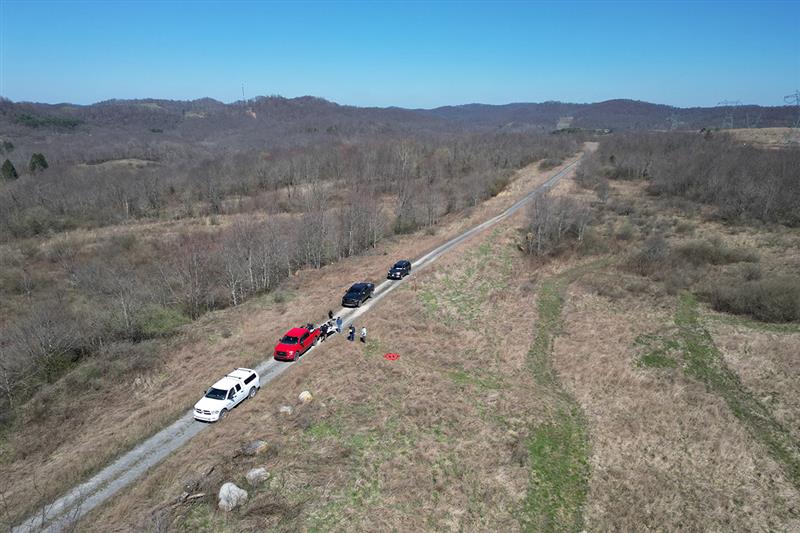
Invasive Species VS. UAVs
Image: Donn Bartram
Researchers at West Virginia University are using UAVs to develop tools to detect, map, treat and monitor invasive plant species with a grant from the Richard King Mellon Foundation. Multiflora rose is an invasive shrub that threatens native plants in more than 40 states, including West Virginia and Pennsylvania. This project aims to equip UAVs with sensors to collect environmental data in a designated area of southwestern Pennsylvania over multiple seasons. The research team will use that data, combined with machine learning technology, to develop software that can identify multiflora rose and, eventually, other invasive species.
Protecting Farms with GIS
Image: Daniel Balakov/E+/Getty Images
American Farmland Trust (AFT) is partnering with government agencies and advocacy groups in South Carolina to deploy GIS mapping tools to predict areas at the highest risk of development in the state. Palmetto 2040: Visioning Alternative Futures, Launching Solutions is a geospatial modeling and policy analysis tool designed to identify and model future outcomes. This mapping tool will project what land in South Carolina is at highest risk of development by 2040. The analysis will consider both rapid population growth and climate change impact on settlement patterns and agriculture, according to AFT.
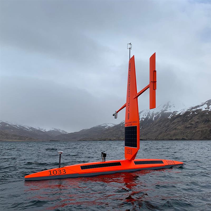
USV Take Hurricanes
Image: SailDrone
Saildrone is deploying 12 uncrewed surface vehicles (USV) into the tropical Atlantic and Gulf of Mexico this summer, supporting research by the National Oceanic and Atmospheric Administration (NOAA) to advance hurricane forecasting. Ten USVs will be deployed from St. Thomas, U.S. Virgin Islands; St. Petersburg, Florida; and Charleston, South Carolina; to operate in areas with a high probability of intercepting a storm, as indicated by historical data. Two vehicles will remain on land, ready for quick deployment in the event of an approaching hurricane. NOAA will use the data collected by the USVs to improve hurricane forecast models.
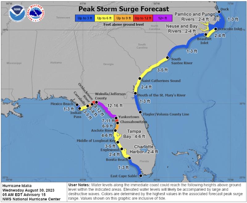
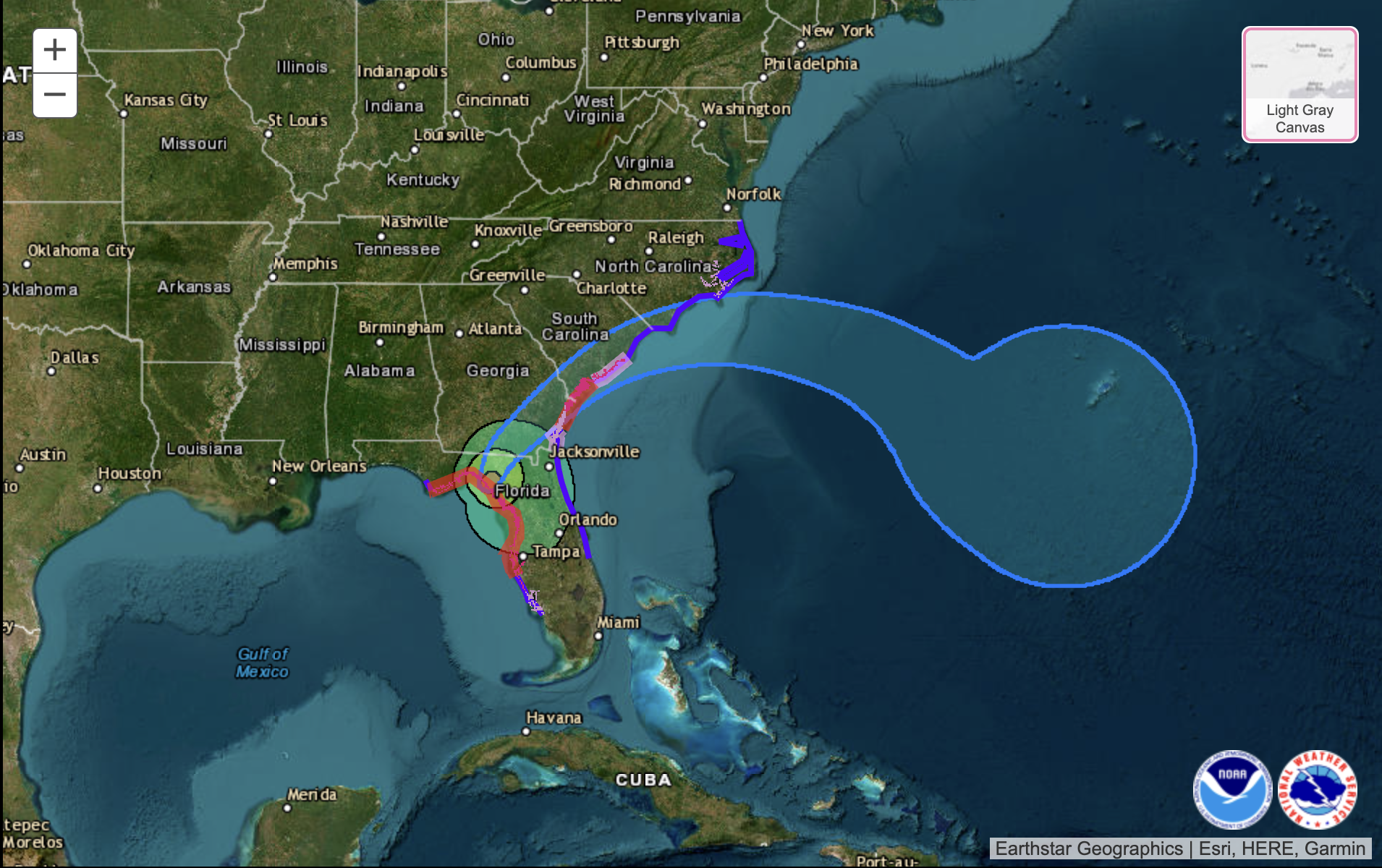
According to the U.S. National Hurricane Center (NHC), Hurricane Idalia made landfall along the Gulf Coast of Florida around 7:45 a.m. EDT on August 30 as a Category 3 hurricane. The NHC is continuing to map the storm’s path, and as of 9:00 a.m. EDT, a catastrophic storm surge was occurring with damaging winds spreading inland over Northern Florida.
Idalia is expected to bring excessive rainfall along its path from Florida through the Carolinas. The heavy rain could shift depending on the storm’s exact path.
Peak storm surge forecast in Florida. (Image: National Hurricane Center)
This hurricane and future storms this hurricane season, have the potential to become supercharged as sea surface temperatures have clocked record high temperatures.
Idalia is the ninth named storm to form in the Atlantic in 2023.
In late May, the National Oceanic and Atmospheric Administration (NOAA) predicted that there would be 12 to 17 named storms this year. However, on Aug. 10, NOAA revised its estimate to 14 to 21 storms.
There were 14 named storms last year, after two extremely busy Atlantic hurricane seasons in which forecasters ran out of names and had to resort to backup lists, reported The New York Times.
Readers can stay updated with Hurricane Idalia at the NHC website.
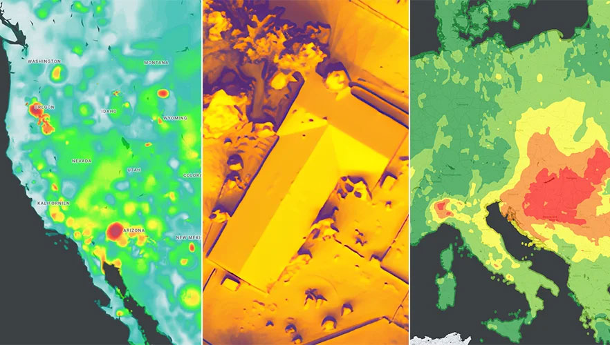
Google has released three Google Maps application programming interfaces (APIs) for developers to map solar potential, air quality and pollen levels. The three APIs apply artificial intelligence (AI) and machine learning, along with aerial imagery and environmental data, to provide up-to-date information about these three variables, enabling developers, businesses, and organizations to build tools that map and mitigate environmental impact.
The Solar API utilizes mapping and computing resources to design detailed rooftop solar potential data available for more than 320 million buildings across 40 countries including the United States, France and Japan. To obtain this data, the AI model extracts 3D information about roof geometry from aerial imagery, while considering past weather patterns and energy costs, enabling quicker installation of solar panels.
The Air Quality API shows air quality data, pollution heatmaps, and pollutant details for more than 100 countries around the world. The API validates and organizes several terabytes of data an hour from multiple data sources — including government monitoring stations, meteorological data, sensors and satellites — to provide a local and universal index.
Google Maps uses machine learning and live traffic information to predict different pollutants in an area at a given time. The Air Quality API offers companies in healthcare, the automotive market and other forms of transportation the ability to provide accurate and timely air quality information to their users.
The Pollen API shows current pollen information for common allergens in more than 65 countries. The API provides localized pollen count data, heatmap visualizations, detailed plant allergen information, and actionable tips for allergy-sufferers to limit exposure. To obtain this information, Google Maps uses machine learning to determine where specific pollen-producing plants are located.
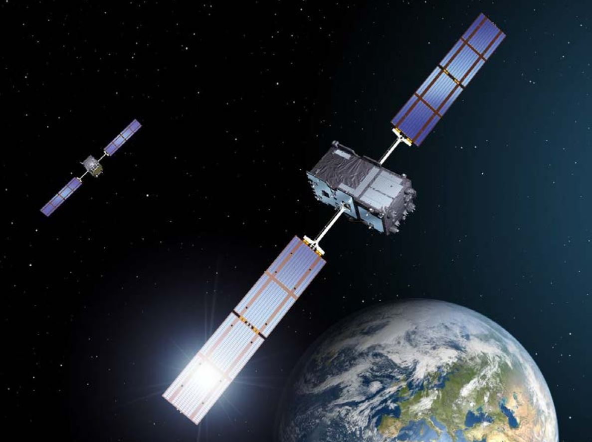
The Galileo Open Service has been upgraded with three features added to its I/NAV message, one of the four message types broadcast by Galileo satellites. These features are now available to all Galileo Open Service users.
The process of upgrading the Galileo Full Operational Capability constellation satellites has been finalized and the I/NAV improvements are openly accessible through the I/NAV message carried by the E1-B signal. If users have experienced delays when turning on a GNSS device, the recent I/NAV improvements may reduce them significantly, reported the European Union Agency for the Space Programme (EUSPA).
The I/NAV message is now faster and offers more robust positioning. The Reed Solomon Outer Forward Error Correction (RS FEC2) increases demodulation robustness, which enhances the sensitivity. It also improves the overall time to retrieve clock and ephemeris data (time to CED) with the broadcasting of additional, redundant CED information while allowing for the device to restore potentially corrupted data autonomously.
The Reduced CED (RedCED) enables fast initial positioning, with lower than nominal accuracy, by decoding a single I/NAV word, while waiting to receive the four I/NAV words carrying the full-precision CED.
The combination of RS FEC2 and RedCED enables I/NAV to obtain a first course position solution faster and to reduce the time required to obtain a first full accuracy solution (RS FEC2). This translates into a reduced time to first fix (TTFF) for the Open Service users, particularly when operating in harsh environments.
Additionally, the improvements benefit applications working in assisted GNSS (A-GNSS) mode, through the Secondary Synchronisation Pattern (SSP). In A-GNSS mode, when navigation data is received from non-GNSS channels and the receiver’s knowledge of the Galileo System Time is affected by a relatively large error, typically in the order of a few seconds, the clock uncertainty must be resolved quickly and stably.
With the I/NAV improvements, receivers will be able to do this via the new SSP feature, thus reducing the TTFF, also in A-GNSS mode.
While the I/NAV improvements are fully operational, EUSPA will launch a testing campaign open to receiver manufacturers, that will consist of several testing windows. The tests will allow the participants to have a confirmation of the correct implementation of the OS SIS ICD 2.0 — i.e., the right processing of the three I/NAV improvements in their products.
The tests will be conducted at the laboratories of the European Commission’s Joint Research Centre in Ispra, Italy, and of the European Space Agency ESA/ESTEC in Noordwijk, The Netherlands.
EUSPA will assign each applicant to one of the two laboratories depending on the specific conditions and availability.
An exclusive interview with Jürgen Pielmeier, managing director, IFEN. For more exclusive interviews from this cover story, click here.
In which markets and/or applications do you specialize?
IFEN is offering RF simulation solutions for all GNSS markets, except the defense market with encrypted signals. The major market in recent years was the ‘New Space’ market, mainly focused to design and test PNT navigation solutions as part of (primarily) LEO satellite constellations using existing GNSS systems. With the many new players around the world, there are many market opportunities. To be successful in this ‘New Space’ market requires simulation support of all GNSS systems and signals, modelling LEO dynamics and environment and providing multiple RF-outputs (enabling systems with several GNSS antennas located on the satellite). With our latest ‘NCS NOVA+’ RF simulator, support of up to 4 RF-antenna simulations is possible. From basic RF system up to integrated SIL and HIL systems, the level of required solutions is very diverse by the different applications. The IFEN RF simulator is also offering a full ‘radio occultation’ simulation capability specifically for this market.
The second important market is the automotive/maritime PNT market requiring fully integrated HIL simulation solutions. Excellent integration capability into external environment simulation systems with a rich set of interfaces and short latencies are keys for this market. To further penetrate this market, IFEN will implement some major enhancements during this and next year within its RF simulator products.
How has the need for simulation changed in the past five years, with the completion of the BeiDou and Galileo GNSS constellations, the rise in jamming and spoofing threats, the sharp increase in corrections services, and the advent of new LEO-based PNT services?
Today, supporting all existing GNSS systems with all related signal components on all frequencies is a must have for all high-end RF simulators. Keeping the RF simulators up-to-date with the new and continuously evolving GNSS signals is required to be sustainably competitive. Specifically, beyond the L-band signals, we are also fully supporting the S-band signals of the NavIC constellation. The continuously increasing number of available GNSS satellites and signals requires that the RF simulator capabilities are fully scalable to provide sufficient resources to simulate all signal channels. Our new NCS NOVA+ simulator is our first RF simulator with strong scalability capabilities, to be further extended in the coming years.
In recent years, adding support for the simulation of jamming and spoofing threats was a major driver for the market. Our latest RF simulator generation ‘NCS NOVA+’ is fully supporting all types of jamming and spoofing, fully integrated into our RF simulators to enable coherent signal generation. With the coming ‘DFMC’ (SBAS/GBAS dual-frequency multi-constellation) based safety-of-life and automated driving applications, the need to support advanced jamming and spoofing simulation solutions will be a continuous driver also for the future.
Adding the ‘High Accuracy Service’ (HAS) PPP-correction capability on Galileo E6-B signal in our coming V2.9 release is driven by the increased request for PPP corrections services. We expect further improvements here in the coming years, especially to cover the emerging PPP-RTK market needs.
With the coming age of LEO-PNT services, this is the most important driver for the next five years, extending the signal frequencies beyond the current L- and S-band signals, seeing new modulations, two-way transfer and many more topics. This will require strong development efforts on the RF simulator side, to provide suited RF test tools in time to LEO-PNT system designers and developers, but also the related user terminal developers. IFEN is currently preparing to take this next major step in its RF simulator capability portfolio.
In particular, regarding some of the new PNT services being developed, how do you simulate them realistically without the benefit of recordings of live sky signals?
Facing the lack of live sky signals when developing RF simulator capabilities is a continuous challenge. It requires to a certain signal simulation flexibility designed into the receiver, good and theoretical understanding of specific implications of new designed signals. As soon as real signals are then available, simulation and real signals will be compared and if required the simulation fidelity will be adjusted to meet the real signals.
Are accuracy requirements for simulation increasing, to enable emerging applications?
Concerning the core accuracy parameters requested in recent years, we saw no increase in required accuracy, as the typical requested accuracy are anyway far beyond the real signals accuracy.
Are all your simulators for use in the lab or are some for use in the field? If the latter, for what applications and how do they differ from the ones in the lab? (For starters, I assume that they are smaller, lighter, and less power-hungry…)
Currently all our simulators are designed for usage within the laboratory. However, we recognize an increased request for in-field capable RF simulators, specifically to perform spoofing of real SIS to test deployed GNSS receivers in the field. Offering a portable in-field solution is in the mid-term planning, but not a current driver for our developments.
What are some of your recent successes?
The most important recent success is the Galileo 2nd generation Test User Receiver contract from the European Space Agency. Within this contract, the ‘NCS NOVA+’ simulator as RF test tool will be upgraded to full G2G signal generation capability. The new already implemented G2G signals enabling shorter TTFF, improved acquisition performance but also higher updates rates (e.g. for PPP-RTK). Up to end of the year the G2G signal will be fully implemented in our RF simulator, including the next generation of advanced authentication solutions.
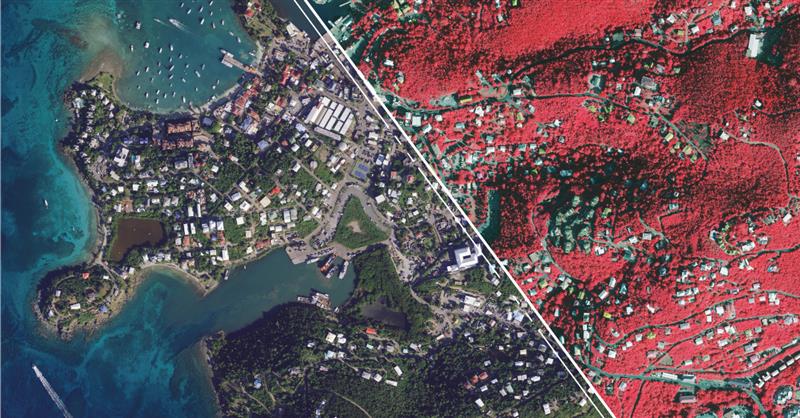
Hexagon’s Geosystems division has updated high-resolution aerial data covering the entire Commonwealth of Puerto Rico and the U.S. Virgin Islands as part of the HxGN Content Program.
Captured during the 2021-2023 flying seasons, the data set includes four-band, 6-inch resolution orthorectified imagery of Puerto Rico — except Isla Mona and Isla Desecheo, which are offered at 12-inch resolution. In the U.S. Virgin Islands, four-band orthorectified imagery of St. Thomas and St. John Islands are offered at 6-inch resolution and St. Croix Island at 12-inch resolution.
Additionally, updated 12-inch resolution digital surface model data of both regions are available.
In the past, aerial imagery from the HxGN Content Program has served as baseline data sets with unbiased records of property and infrastructure conditions prior to events such as Hurricanes Irma and Maria in 2017 and the earthquake of 2019. The imagery has also provided information for emergency preparation, response, and management.
In addition to emergency management, the HxGN Content Program aerial imagery is used in engineering, agriculture, utility, mapping, and artificial intelligence/machine learning applications.
The HxGN Content Program offers a large library of high-resolution aerial imagery, elevation data, 3D models and analytics of North America and Western Europe.
The refreshed Puerto Rico and U.S. Virgin Islands orthoimagery and DSMs are available now through a streaming subscription using standard mapping APIs or via pixel download on the Hexagon Digital Reality (HxDR) Data Store.
An exclusive interview with Tim Erbes, Technical Director, Safran Federal Systems (formerly Orolia Defense & Security). For more exclusive interviews from this cover story, click here.
What are currently the key challenges for simulation?
One of our big challenges is determining what performance requirements are necessary for our users. Often, they can’t determine what the specs need to be. All they know is that they need it to work. “I need this receiver from one company, this IMU from another company, and the simulator I got from you guys to work together and I need the performance to match reality.” It can be very challenging to say, “What are the requirements for the simulator? How accurate does it need to be? What types of things matter in this integration?”
Often, we’re left trying to figure that out. So, that’s an interesting, maybe unexpected challenge. It’s easy to look at the datasheet and see what some specs are, but it’s a much harder thing to say, “Well, what do you need the specs to be?” So, we’ve been working with our customers to try to nail down some of those specs, particularly with Wavefront. We have some specs on such things as phase alignment and phase stability. But how do you translate that into something like “Well, I just want the CRPA to work the same in the lab as it does in the real world?” There’s not a direct, easy way to do that. We’re in the middle of trying to figure that out. That’s definitely one of our challenges.
What about the increase in jamming and spoofing threats?
In the last five years, we’ve seen a lot more open talk about jamming and spoofing in the world. The receiver manufacturers must think about this a lot more. What’s interesting from a simulator point of view is that this is not actually new for us. We have the advantage that we’ve been designing to program requirements for years and they have included jamming and spoofing for years. So, in a way, simulation is ahead of this state of the world. Jamming and spoofing are not new or hard ideas for us. In fact, spoofing is similar to simulation. So, we already know how to do that.
Image: Safran Federal Systems (formerly Orolia Defense & Security)
However, jamming and spoofing are new to programs and integration labs. So, there might be platforms where they’re now testing against jamming or spoofing requirements where in the past, maybe they didn’t do that. They certainly can use our simulators to help them do that. However, we’re not seeing a lot of new requirements coming to us saying we need new jamming or spoofing capabilities, because we already have them. Luckily, we are future oriented regarding the jamming and spoofing requirements, so those really haven’t been a challenge for us yet.
That can always change, right? If new requirements come up, such as higher data rates or wider bandwidth waveforms or different types of waveforms, then we would have to adapt and add support for that kind of stuff. As of right now, however, we aren’t really seeing that. So, luckily, we’re prepared for that. As for the industry as a whole, there has definitely been a big movement in the last few years to understand the effects of jamming and spoofing. Simulation is a big part of that.
What about the completion of the BeiDou and Galileo constellations?
For a long time, we simulated four constellations. Then that began to get fuzzy. Do you consider SBAS a constellation or is that just an augmentation? Do you count EGNOS and other supplemental constellations for the other constellations? What about NavIC and QZSS? Before you know it, you start to lose track of exactly how many you have. We just released our 8th constellation, Xona.We’re going to be demonstrating it at JNC.
Tell me more about that.
We are trying to have all the constellations and that can be a fuzzy definition. Does that mean all that are up there right now or all that will be up there in the future? We’re trying to be forward looking and add everything that is going to be up there or might be up there so that lab users can develop and test. Multi-constellation simulation is a particularly challenging problem for groups that don’t have simulators. If you’re just doing research on, say, GPS, and want a new code, you might be able to do that in a lab on your own. But as soon as you say, “I want to do research on whether this LEO constellation helps navigation on a receiver that also uses Galileo and GPS,” suddenly, your research requires a full multi-constellation simulation.
There are two choices. One is to have a simulator do the constellations that already exist, and then you have some research to add constellations. That can be very challenging, especially with time alignment and things like that. The other is to have a simulator that can do all the constellations. That would be the easy choice, right? That presents a problem with such things as LEO navigation being on the rise and these constellations that are just emerging, that are still not even fully defined.
So, we’re trying to build those into our simulation products, to help researchers and decision makers determine whether these will be useful features to add to their receivers or their systems. We have the advantage of having a software-defined architecture. We designed the software so that it is easy to add new constellations to it. Basically, once we’re given a proper ICD, we’re only a couple of months away from a first draft implementation of that new signal. Then we iterate. There used to always be a government-driven, multi-year program to develop an ICD. Now, we have this new concept of the signal manufacturers. We’re seeing private companies release signal specs. That’s a very different way of creating a signal in a constellation. So, sometimes you don’t get much time between when the ICD is available and when simulator users want to use that constellation. Having a software-defined architecture really helps us move quickly. We can add such things as Xona very fast.
Xona told me a couple of days ago that they will soon put out an ICD. What’s the difference between actual signals that you can record and play versus something that’s only on paper?
That’s a great point. Probably many people don’t realize, when they first look at this, that what’s in the ICD and what’s on live sky are sometimes very different. Is the simulator supposed to match live sky? Or is it supposed to match the intended final state of the constellation, according to the ICD? This is a huge topic for M-Code, which is ever changing, and has a very large ICD that’s been released. Space Systems Command/Military Communications & Position, Navigation, & Timing (MCPNT) controls the features and releases them incrementally. We’re constantly having to make changes to the simulator to match those releases. The same is true for the other ICDs. At the Institute of Navigation Joint Navigation Conference (JNC), we will demonstrate an expanded PRN. I think this showed up in the ICD a couple of years ago, but it’s not used by any users yet. Some of the receiver manufacturers are starting to look at using PRNs beyond 32. So, we’re adding that to the simulator. This has already happened for BeiDou as well. I think their ICD goes up to more than 60 satellites. It’s an ever-changing race. The ICDs are constantly being updated and we’re trying to update the simulator.
Image: Safran Federal Systems (formerly Orolia Defense & Security)
Meanwhile, live sky is many years behind the paper, right? This creates an interesting challenge: when you design a system, are you designing it for today or for the future? We have users in both groups. We have users that only care about what is happening today, because they need a model. Maybe you want to model a specific mission and you want to make sure that everything’s going to go properly. Or maybe you’re designing a system that you want to release in three or four years, and you want to make sure that it’s going to work with the state of the system then.
A big challenge is to make sure that we’re keeping pace with all these ICDs. There are more constellations than ever and the technology makes it easier to change signal architectures. We’re seeing signals change faster than we’ve ever seen them change before. We go to conferences and hear about such things as on-orbit reprogramming and signals that might even change specs while they’re being transmitted. Maybe they don’t even have to have a fixed bandwidth or fixed bit rate. We’re going to start talking about signals that can reprogram on the fly. That’s going to make simulation more and more challenging. The technology exists to do this.
Software-defined waveforms is a very logical step. In the software world, we have this concept of version nightmare. When you have 20 different pieces of software that are interdependent, it can get very challenging. We’re going to start to see that in simulators. We’re going to see, “Hey, what version of navigation authentication are you using? We updated it six months ago. Are you using the new one or the old one? Which one should we use?” Well, it depends on what your receiver is using. It’s going to be interesting and challenging to keep all this straight in the next few years as things evolve. Certainly, however, our goal is to be there for all of it and to be as fast and as forward thinking as we can for our customers. That means that we also need to know what our customers need. So, we’re always looking for feedback and requests, what challenges our customers face and we’re responding to those requests.
Tell me more about the difference between simulators used by receiver manufacturers in their labs as they’re tweaking receivers or developing new ones vs. simulators used for mission planning.
The simulators are the same, but they’re used in very different ways. In most lab simulation, what the constellation looks like that day doesn’t matter very much. They can just run with a default constellation for a given day. They’ll run that scenario hundreds or thousands of times and never need to change it because they’re testing parts of the receiver that don’t care a whole lot about the specifics of what’s happening.
Whereas missions are time- and location-specific.
Yeah, exactly. They want to know which satellites will be overhead at an exact time and place. It’s not so much a problem anymore, but there used to be certain days and times when you would not get enough satellites in view, or you might have very bad dilution of precision, and your mission might actually fail. We’re past those days. There are now enough satellites up there. Most receivers will navigate within their specs most of the time in most places. However, for critical missions, such as military operations or rocket launches, you might not want to just assume that any day is a good day. So, if you’re about to launch a rocket, you might want to check. “What does the constellation look like right now?” The challenges that brings is that simulators have a default constellation, but the constellations are constantly changing.
When you’re doing real day mission planning, the big problem isn’t so much how to generate a signal, it’s how to find out what’s happening today. That’s really the nature of the problem because what’s out there today is different from what was happening yesterday or what will happen tomorrow. You might have unhealthy satellites. You need to know that if you want to model them. It becomes a big challenge to get all the right data into the simulator. Once all that data is in there, then it’s the same as any other simulation.
Are there good sources for current data on GLONASS, BeiDou and Galileo?
Image: Safran Federal Systems (formerly Orolia Defense & Security)
There are a couple of websites that provide information about where the satellites currently are. However, we’ve found that each one of those sites has its own challenges. Some are maybe 30 minutes out of date, which is pretty good, but puts the satellites in slightly different spots. Some of those sites only support some of the constellations. We’re talking about multiple countries and they don’t all agree on how this should be done. So, there’s not a single point that you can visit to get all the satellite data. There are a couple of companies that try to fix this. U-blox has AssistNow; Qualcomm has an assist for its cellular receivers; Trimble, NovAtel, and a couple of other companies have their error correction services to which you can subscribe to get some of that data.
If you want real-time up-to-date ephemeris for all the constellations, that is challenging. There are one or two options we have found that seem to work, but they each have their disadvantages. Maybe they don’t have all the satellites. Again, we’re talking about versioning issues. So, if you’ve designed your system with a certain version of an ICD and they’ve added more satellites since, those new SVs maybe aren’t so important for your users, so you don’t publish them. Other users want those satellites. So, we see versioning issues in these data streams. For example, we use the CORS network to get a lot of GPS data but that whole network, as far as I know, is only running the legacy data. As far as I know, no network is distributing the L1C modernized data that we will need at some point. So, as we launch new signals and constellations, we need the networks to provide this new data.
What are some other challenges?
For us, being a software-defined simulator on a platform dependent on software-defined radio (SDR), we’re constantly looking at what’s changing in the SDR technology community. There’s always some interesting stuff happening there that we try to incorporate. We don’t have any big announcements this year, as far as new architectures or anything like that. However, the SDR community is evolving. It’s still a rather new industry. A few years ago, we were an early adopter of SDR technology for mass deployment. Now, we’re seeing some more mature SDRs starting to push such things as channel count and coherency. We will probably take advantage of that in the future.
The other interesting thing technology-wise is that we’re also a GPU-dependent technology. So, as the GPU industry continues to evolve and makes bigger and faster GPUs, we get a relatively low-cost way to upgrade. We don’t have to do a lot of R&D to upgrade to a new GPU. For our users that means that the number of signals they can generate on their simulators is always increasing even using the same hardware from one generation to the next. Our first simulator did 75 signals; the next version did 150. We could build a system that did more than 1,000 signals, but our users don’t need it.
I assume that the growth curve for GPUs is steeper than that for signals.
I think that you’re right about that. I’m sure glad they do, because then something like Xona shows up and we don’t have to rearchitect our system to generate 300 signals, right? At JNC we will show expanded PRN, 300 Xona satellites in the constellation, and a 10 fold improvement on Wavefront performance specs.. We will continue to build simulators that meet our customers’ requirements. Besides GPUs, a lot of the technology involves software R&D and signals. The stuff that we do digitally inside of our system that allows us to do things like extremely precise phase alignment on Wavefront, for example. We spent a lot of time developing that stuff.
A roundup of recent products in the GNSS and inertial positioning industry from the August 2023 issue of GPS World magazine.
SURVEYING & MAPPING
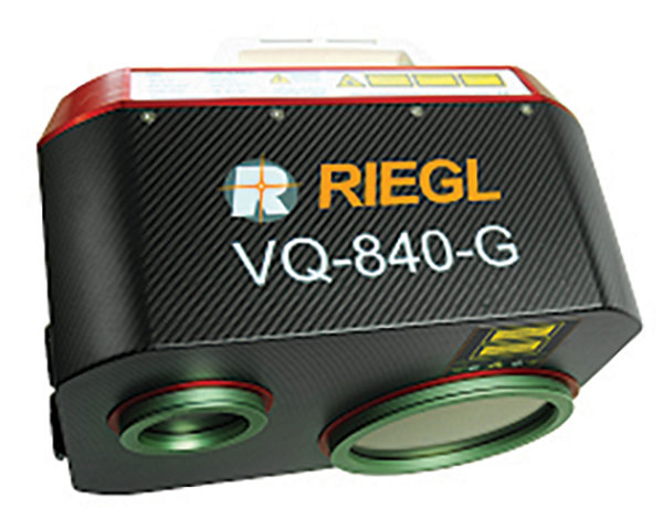
Laser Scanner With several integration options
The VQ-840-G is a fully integrated compact airborne laser scanner designed for combined topographic and bathymetric airborne and UAV-based surveying. The system is offered with an optionally integrated and factory-calibrated inertial measurement unit/GNSS system and can be complemented with an optional camera or IR rangefinder. It also has an optional integrated inertial navigation system. The scanner carries out laser range measurements for high resolution surveying of underwater topography with a narrow, visible green laser beam, emitted from a pulsed laser source. The VQ-840-G has high spatial resolution due to a measurement rate of 200 kHz and high scanning speed of up to 100 scans/second. Riegl, riegl.com
Laser Scanning System A versatile reality capture solution suitable for surveying, construction and engineering users
The X9 is designed to enhance performance in more environments while leveraging Trimble’s X-Drive technology for automatic instrument calibration, survey-grade self-leveling and laser pointer for georeferencing. The X9 expands on Trimble’s X7, delivering longer range, higher accuracy, shorter scan times and sensitivity, improving scan results. Advanced processing and a high-performance laser increase the sensitivity of all scans, enabling the X9 to capture difficult dark or reflective surfaces. A new center unit design also improves signal transmission for better scan quality. The X9 provides accurate and dependable data, enabling confident decision making both in the field and in the office through in-field registration with Trimble Perspective and FieldLink software by minimizing the need for target deployment. The auto-calibration eliminates the need for annual calibration. In addition, the X9 includes survey-grade self-leveling with the industry’s widest compensation range for fast, easy setup. The X9 data can be delivered directly from the Perspective or FieldLink software to Trimble’s office software — including the Realworks 3D scanning software — business center office software, SketchUp and Tekla, or exported to industry-standard formats to produce application-specific deliverables. Trimble, trimble.com
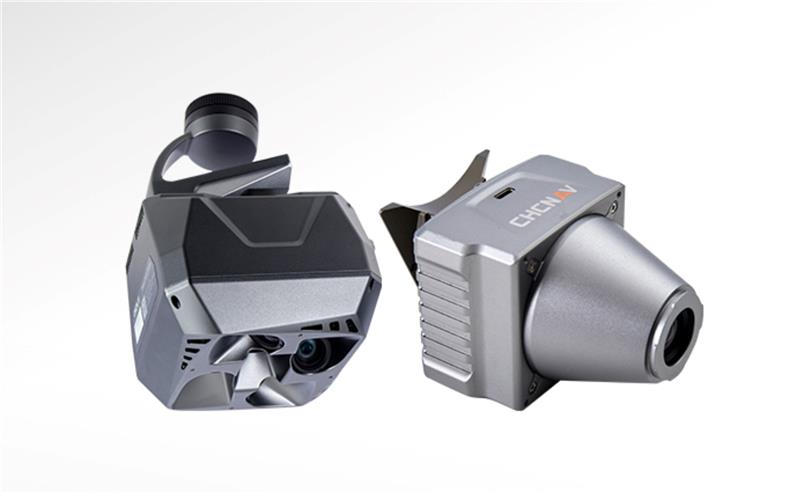
Survey Cameras For photogrammetric applications and to complement lidar survey data
The C5 and C30 orthographic and oblique cameras are designed for aerial surveys. The systems provide high-quality imaging solutions for photogrammetric applications and to complement lidar survey data. The C5 camera is an efficient and lightweight system for aerial surveys, weighing 290 g for increased flight endurance. Its compact size of 75 mm x 63.5 mm x 102.5 mm allows easy integration into UAVs. The C30 camera’s weight is 600 g with a size of 110mm x 108 mm x 85 mm. The C30 is also designed for aerial surveying. The C5 and C30 cameras’ universal installation design makes them compatible with a wide range of fixed-wing and rotor UAV platforms. Both cameras are supported by the CHCNAV’s BB4 Mini and P330 Pro UAVs as well as the DJI’s M300 RTK. The C5 and C30 cameras give maximum flexibility for photogrammetric applications. They can be used independently on real-time kinematic-enabled UAVs to capture high-resolution imagery or installed directly on the CHCNAV’s lidar series to colorize point cloud data. This feature allows seamless imagery and lidar data integration for a more complete view of the surveyed area. CHC Navigation, chcnav.com
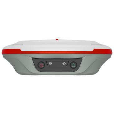
GNSS Palm RTK For surveying and mapping, GIS and more
The T20 is light, weighing 0.68 kg, and has low power consumption with 12 hours of battery life. It integrates functions such as a GNSS module, datalink module, 4G, 5.0 dual-mode Bluetooth, data memory system and more. Powered by the SinoGNSS K8 high precision module, the T20 has 1,590 channels and can track all running and planned constellations including GPS, BDS, GLONASS, Galileo, QZSS and satellite-based augmentation systems. Additionally, the anti-interference algorithm enables the T20 to maintain accurate positioning and perform well in complex environments, providing surveyors with high-quality measurements. The T20 is equipped with a third-generation inertial measurement unit from ComNav, which can be tilted and measured at an angle up to 60°. The T20 is also equipped with a U50 datalink module, which enables it to switch between base and rover. The T20 is compatible with mainstream real-time kinematic receivers on the market. ComNav Technology, comnavtech.com
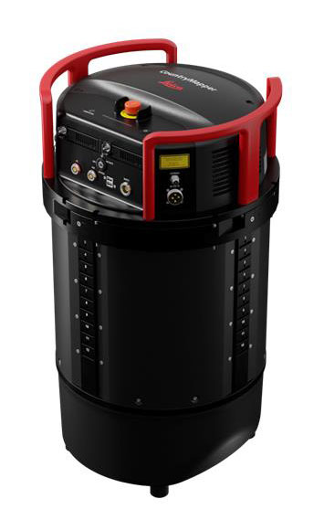
Hybrid Imaging and Lidar Sensor Designed for airborne mapping
The CountryMapper is designed for large-area imaging and lidar mapping. Combining a large-format photogrammetric camera with a high-performance lidar unit into a single system, the CountryMapper collects foundational geospatial data simultaneously to support a wide variety of user applications. The CountryMapper combines imaging and lidar sensor modules into a highly efficient hybrid airborne system. The sensor features CMOS-based Leica MFC150 camera modules that leverage true mechanical forward-motion-compensation to deliver high image quality. The sensor’s new Hyperion3 lidar unit features 60° field of view, improving the performance and flexibility of the system compared to previous lidar modules, while reduced laser divergence provides greater planimetric accuracy and better foliage penetration. The CountryMapper fully integrates with Leica HxMap multi-sensor end-to-end processing workflow, enabling distributed processing of images and point clouds to optimize productivity for very large data sets. The CountryMapper supports applications such as orthophoto generation, terrain mapping, hydrography, forestry monitoring and infrastructure management. Users of previous-generation sensors can leverage their initial investment and upgrade their systems to the CountryMapper configuration. Leica Geosystems, leica-geosystems.com
MOBILE
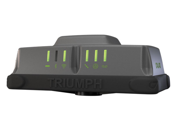
GNSS Network Rover Complete with an integrated MEMS IMU
The Triumph-3NR (T3-NR) is a small, lightweight GNSS network rover with more than 25 hours of run time on a single charge. The T3-NR easily connects to real-time networks for corrections to get GNSS real-time kinematic with inertial measurement unit tilt compensation. The network rover has 874 channels and can track all constellations. It features an internal GNSS antenna, Wi-Fi, Bluetooth, and is USB compatible. The T3-NR is suitable for demanding industrial applications. JAVAD, javad.com
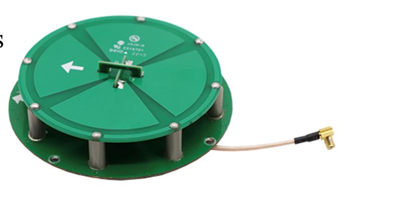
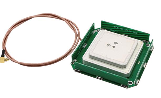
Antennas Suitable for lawn mowers and other mobile applications
The HX-CSX014A is a high gain, low profile and compact antenna with a new structure that simplifies integration into lawn mowers and minimizes the overall machine dimension. It features small size, high sensitivity and low power consumption. The HX-CSX231A, is a ready-to-use GNSS antenna with a highly reliable structure that makes it small and lightweight. It exhibits 4.5 dBi high gain performance with ultra-low signal loss. It also delivers wide beam width that covers wide frequencies with high marginal gain, a perfect option in complex environments. Additionally, the HX-CSX231A’s advanced LNA features improved signal filtering, out-of-band rejection, restrained unwanted electromagnetic interferences and a strong multi-path reduction capacity. Harxon, en.harxon.com
DEFENSE
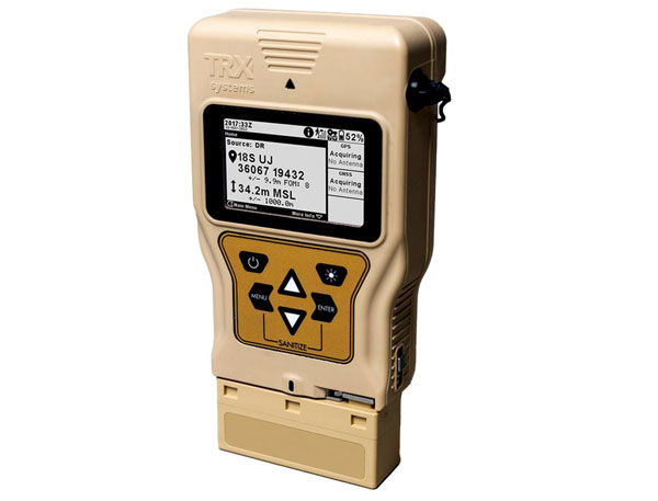
PNT Device Enables dismounted maneuver operations even where GPS is compromised or denied
The TRX DAPS II provides assured positioning, navigation, and timing (PNT) to dismounted users by disseminating assured position and time to dependent devices in GPS-challenged environments. TRX DAPS II fuses inputs from M-code GPS, inertial sensors, and complementary PNT sources. It is a small, lightweight PNT device that supports both standalone operation and integration with the Nett Warrior ensemble. It also can distribute PNT information to a customized tactical watch. The TRX DAPS II solution employs a modular architecture and adheres to Army PNT interface standards, facilitating the addition of new PNT sensors as threats evolve. This device will be in production for the Army later this year. TRX Systems, trxsystems.com
TIMING
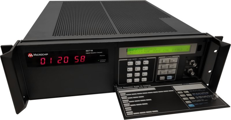
Image: Microchip Technology
Atomic Clock Maintains system synchronization when GNSS signals are denied
The 5071B cesium atomic clock can perform autonomous time keeping for months in the event of GNSS denials. This device is the next-generation commercial cesium clock to the 5071A. The 5071B is available in a three-unit height, 19-in rackmount enclosure, providing a compact product to work in environments where it can be easily transported and secured versus a larger alternative designed specifically for laboratory environments. The 5071B has upgraded electronic components to address possible obsolescence or non-RoHS circuitry. The clock provides 100 ns holdover for more than two months, maintaining system synchronization when GNSS signals, such as GPS, are denied. As a cesium beam tube product with no deterministic long-term frequency drift, the 5071B provides absolute frequency accuracy of 5E-13 or 500 quadrillionths over all specified environmental conditions for the life of the product. For military applications requiring rapid deployments for system radars, 5E-13 stability eliminates the need for the acquisition of external synchronization sources prior to radiating. Microchip Technology, microchip.com
OEM
GNSS Positioning Modules
For multiple applications
automation of moving industrial machinery, and the ZED-F9P-15B provides customers in the mobile robotics market with an L1/L5 option in addition to the L1/L2 bands. These two modules are based on the u-blox F9 high-precision GNSS platform. The NEO-F9P and the ZED-F9P-15B GNSS modules feature concurrent reception of GPS, Galileo, and BeiDou; multi-band L1/L5 real-time kinematic; short convergence times; and reliable performance. The modules deliver centimeter-level accuracy in seconds and come in small, high-precision form factors.
Its small size, coupled with very low power consumption and ANN-MB1 antenna compatibility, makes the NEO-F9P suitable for a wide range of uses. Offering reliable and efficient positioning, the module supports open as well as standards-based correction services for enhanced performance, such as the u-blox PointPerfect GNSS augmentation service. u-blox, u-blox.com
Image: Septentrio
GNSS Receiver Module
Features built-in AIM+ technology for interference mitigation
The mosaic-X5 is a multi-band, multi-constellation GNSS receiver in a low power surface mount module with a wide array of interfaces. It is designed for mass market applications such as robotics and autonomous systems — capable of tracking all GNSS constellations, supporting current and future signals. The mosaic-X5 has an update rate of 100 Hz, is easy to integrate, and is optimized for automated assembly. The mosaic-x5 is suitable for autonomous vehicles, logistics and port operations, mining and construction, precision agriculture, rail, robotics, surveying and mapping, UAVs and more. Septentrio, spetentrio.com
Sitting comfortably in a thin aluminum tube at 35,000 ft, I can continue to communicate via e-mail — and, soon, via video — and write this editorial, while on my way from Portland, Oregon, where I live, to Cleveland, Ohio, where North Coast Media, this magazine’s publisher, is based.
I can safely assume that the pilot knows our position, heading, and speed with great accuracy and receives excellent weather reports. The computer on my wrist (made by the largest manufacturer of GNSS-based consumer devices) and the much more powerful one in the holster on my belt, can do way more than Dick Tracy’s creator, Chester Gould, could have ever imagined a gadget produced by Diet Smith Industries to do.
One thing that communications, navigation, and weather forecasts currently share is reliance on satellites — be they in geostationary Earth orbit (GEO), at 22,000 mi, which are used mostly for weather data, broadcast television and, increasingly, data communication; medium Earth orbit (MEO), at 3,000 mi to 12,000 mi, including GNSS satellites and those that provide Internet connectivity; or low-Earth orbit (LEO), 300 mi to 745 mi, with thousands of satellites in operation today, primarily addressing science, imaging, and low-bandwidth telecommunications needs — and, coming, a new generation of satellite-based positioning, navigation, and timing (PNT) services.
Another thing these feats of engineering share is their foundation on the purest science and mathematics. To take one example, had the designers of GPS failed to adjust the system by 38 ms per day to account for both Albert Einstein’s 1905 Special Theory of Relativity and his 1915 General Theory of Relativity, positional errors would cumulate at a rate of about 6.2 mi each day, making GPS utterly worthless for navigation in a very short time. That’s because Einstein’s 1905 theory leads to the prediction that the atomic clocks on GPS satellites should fall behind clocks on the ground by about 7 ms per day because of their slower ticking rate due to the time dilation effect of their relative motion — while his 1915 theory leads to the prediction that they would be ticking faster than identical clocks on the ground by 45 ms per day due to the curvature of spacetime.
As with most complex technologies, the scientific principles, technical challenges, and policy debates behind GNSS are unknown and irrelevant to more than 99% of the public, few of whom even know that GPS is not the only global navigation satellite system in existence today. The technology is transparent to them. Most of them say “GPS” to refer to GNSS receivers, digital maps, driving directions and traffic data without understanding the separate, though overlapping, technologies, business models and data sources involved. This routinely results in misunderstandings and misattributed complaints and praises — such as when drivers blame “their GPS” (meaning their GPS receiver) for leading them up a dead end that was due to a mapping company being one step behind new construction or praise it for traffic alerts for which they should thank crowd-sourced data and algorithms.
In May the President’s PNT Advisory Board heard a presentation about a National Guard project called NITRO. RNT Foundation President, Dana Goward, recently spoke with the project’s leader, Maj. Gen. Richard R. Neely, Adjutant General, Illinois National Guard, to find out more.
Mr. Goward: Thanks for speaking with us, General. Could you start by telling us what NITRO is and why it’s important?
Maj. Gen. Neely: Of course. NITRO is a project to ensure that the National Guard and our state’s first-responder partners can maintain communications and other critical functions even if we lose GPS timing signals.
NITRO is an acronym for Nationwide Integration of Timing Resiliency for Operations. ]You know how we in the military love our acronyms.
Telecoms and most of the rest of America’s critical infrastructure are dependent on timing from GPS. However, GPS signals are weak, highly vulnerable and under threat.
In addition to bad actors who can and do jam and spoof signals, accidental interference happens all the time. Operations at the Dallas and Denver airports were each interrupted by accident for more than a day last year, for example. A couple of years ago, a passenger airliner almost hit a mountain because of interference with GPS.
Q: It sounds like this is a safety of life issue.
A: It is. Right now, if we lost GPS signals and had to respond to a domestic attack, natural disaster, or other contingency, I am confident there would be additional unnecessary casualties. We are building NITRO so that we can save those lives and keep America safe.
Q: So how does NITRO work?
A: In addition to GPS, it gets multiple sources of space-based and terrestrial time from government and commercial providers. NITRO can use any trusted source. It is not provider- or vendor-specific.
Inputs are combined and compared, matched to the nation’s atomic clocks keeping Coordinated Universal Time, and users are sent the best accurate time multiple ways including over fiber, terrestrial broadcast, and resilient wireless networks.
Another great way in which I think it will be useful: NITRO gives us a common operating picture that can help detect and terminate GPS disruptions and anomalies around the country.
Q: Is the National Guard the only user?
A: Absolutely not! This is a state/federal partnership. The states’ Adjutant Generals are working with their Homeland Security Advisors to make it available to state, local, and tribal first responders. In some instances, also to critical infrastructure.
Even though we are in the early stages of implementation, NITRO is being used by seven states and 256 organizations and it is protecting more than 33 million people, including citizens here in Illinois.
Q: Is NITRO a tasking from the President or Congress? Who told you to do this?
A: NITRO helps execute long standing presidential policy and orders, as well as the recently released National Cybersecurity Implementation Plan. It also meets congressional mandates for backups and alternatives to GPS timing.
However, we created NITRO because we identified a serious threat to the National Guard’s mission execution. It closes 11 operational gaps for us, all without changes to end-user equipment.
Q: With what groups are the NITRO team working?
A: All the states are involved through their adjutant generals, homeland security advisors, and emergency managers. The NITRO board I chair is made up of the adjutant generals from six states.
We are also coordinating across the federal government, especially with the Departments of Homeland Security, Transportation, Commerce, and Energy.
As part of this we are partnering with the Department of Transportation to establish a NITRO engineering and operational site at Joint Base Cape Cod. This will allow engineers from different organizations to see more easily what we are doing and contribute their expertise.
Q: NITRO is going to provide timing signals in places and at times when GPS is not available. Won’t the National Guard also need navigation information?
A: Positioning and navigation are very important, but not quite as critical as timing. So, we are addressing that problem first. And since wireless location and navigation are often based on timing signals, NITRO will provide a good foundation for services and systems that can augment GPS-based navigation.
Q: So, how is the project going?
A: From a technical and operational standpoint, it’s going great. We have very high satisfaction ratings from NITRO users, and states are eager to be connected as soon as possible.
The technologies used are all mature, reasonably low cost, and most components are commercially available. So, engineering-wise it is low risk.
And our team is doing a great job helping folks move from full dependency on GPS to resilient positioning, navigation and timing (PNT) operations.
Q: Do you have any concerns going forward to full deployment?
A: The only thing I worry about is continued funding. Over the next five years we need something less than the cost of one GPS satellite. You would think that would be easy to find for an important effort like this, but it is a state/federal partnership, not a Department of Defense project. So, it falls into a kind of bureaucratic and budgetary no man’s land.
Q: What’s the solution for funding?
A: That’s not our call. The folks at the White House are exploring several alternatives, and I know several members of Congress are also concerned. We see a possibility of this fitting nicely with the recent infrastructure funding bill.
Q: It sounds like NITRO is something America really needs. Let’s hope they find a solution to the funding challenge, and quickly, to keep you on track. Thank you very much for your time!
Anyone keeping up with my columns may know that I have been highlighting the geodesy crisis and programs that advance the science of geodesy (July 2020, November 2022, December 2022, and March 2023). On June 13-15, I had the privilege of participating in a working group event convened by the Geomatics Emerging Scientist Consortium for Education, Research and Capabilities Enhancement (GEO-ESCON). The GEO-ESCON, established in the summer of 2022, is a multi-university consortium serving the need of the Office of Geomatics of the National Geospatial-Intelligence Agency (NGA) for personnel with advanced geomatics expertise, a sustainable pipeline of critical geomatics skillsets, and capabilities enhancement in geomatics and other applied sciences. The 15-member consortium is led by The Ohio State University (OSU), which serves as GEO-ESCON’s managing higher education partner.
GEO-ESCON is part of OSU’s Battelle Center for Science, Engineering and Public Policy in the John Glenn College of Public Affairs. As stated in an OSU press release, OSU was selected for its role with GEO-ESCON because of its longstanding commitment to geodetic education — its collegiate geodetic program is the oldest in the United States and offers undergraduate and graduate degrees in both geodetic engineering and geodetic science.
OSU is home to more than 80 researchers across six colleges who focus on core research and development aspects of geospatial science and technology, including geodesy, remote sensing, photogrammetry, GIS, positioning, navigation, and timing (PNT), computer vision, mobility, smart cities, data analytics, autonomous systems (UAS, UUS and UGV), medical imaging, and precision agriculture.
The GEO-ESCON consortium is designed to create a geographically distributed, multi-disciplinary network of universities to educate the federal geomatics workforce at advanced levels and provide opportunities for applied research and technology development. Higher education institutions are invited to participate in GEO-ESCON based on their capabilities in geomatics. As of July 18, the consortium has 15 members and two additional universities are in the process of becoming members. Click here for all GEO-ESCON member institutions.
GEO-ESCON convened the June Geomatics Challenge Working Group to discuss pressing geomatics challenges and discuss potential solutions. The event facilitated dialogue between representatives from NGA’s Office of Geomatics and academic attendees on geomatics challenges of national priority that could result in actionable proposals to address the challenges. The working group enables representatives of GEO-ESCON member institutions to gain a deeper understanding of NGA’s geomatics priorities, build relationships with NGA leaders, collaborate with colleagues at other institutions, and provide recommendations to GEO-ESCON and the NGA. There were 47 academic participants representing 14 universities.
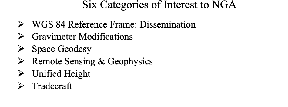
NGA aims to encourage institutions with varied expertise to propose solutions that achieve greater outcomes through collaborative work. The agency provided six broad categories of geomatics challenges for discussion. See the image below for the categories of interest.
Proposals submitted in response to the June Geomatics Challenges Request for Proposals (RFP) will be eligible for funding consideration and selected activities are expected to be awarded before the fall semester.
The word “tradecraft” in the categories of interest was intriguing. In general, tradecraft refers to the skills, techniques, and practices used by professionals in various fields to carry out their work effectively and discreetly. During World War II, however, the term became associated with spy work and now is mostly used to refer to the techniques and procedures of espionage. NGA is concerned with the dramatic drop in the number of individuals pursuing careers in geodesy — that is, the geodesy crisis in the United States.
Event attendees were asked to prioritize the topic(s) that most interested them, so that they could join a small group on the topic to identify issues, and discuss approaches, solutions, and potential actions for the challenge. Several universities had multiple representatives, so they selected different topics aligned with their individual interest.
The meeting had professional workshop facilitators, technical advisors, NGA subject matter experts (SME), and student recorders. Facilitators encouraged the full participation of all attendees to elicit a range of viewpoints and generate previously unconsidered solutions that could bridge differences in approach — resulting in solutions that were supported by many.
The small groups aligned with a specific challenge utilized the expertise of technical advisors — experts in geomatics or related fields with considerable industry, government, and/or research experience — who supported the development and maturation of proposed Geomatics Challenge solutions. The role of technical advisors was to work with the other leaders in their small group to encourage the full participation of all attendees and mentor the groups toward the generation of novel solutions. I was a technical advisor for the “unified height” topic.
NGA’s SME participated in the working group activities and provided additional context for the individual topics, and other unclassified details related to the Geomatics Challenges.
To capture the discussions at the group meetings, student recorders took detailed notes during the small group discussions. The recorders were graduate students — primarily in geodesy or other STEM fields — and they did an excellent job of capturing the discussion, action items, and potential proposals.
As previously stated, individuals self-selected the topic that interested them but over the course of the three-day meeting individuals were asked to participate in other Geomatics Challenge small groups to provide constructive critiques to produce the best research projects. This was an excellent concept that, in my opinion, helped to improve draft proposals and identify new collaborative projects.
As an example, the need for a unified height system that defines, assesses and correlates all height measurement processes became very evident when individuals participating in the “remote sensing and geophysics” topic engaged with the “unified height” topic members. This joint-topic group meeting helped form new partnerships and formulate new proposals.
The GEO-ESCON and the participating institutions have an ambitious schedule of submitting and awarding the grant proposals before the end of the government’s fiscal year. That said, the participants appeared to be up to the challenge and prepared to make it happen. For obvious reasons, I cannot describe any of the projects discussed, but I will highlight them when they become available for public distribution.
For now, I would like to state that GEO-ESCON is a great program, and it supports the advancement of the science of geodesy and geomatics. I believe that integrated and collaborative organizations are necessary for the successful development of geospatial products and services, and GEO-ESCON is the epitome of this concept. If you believe your institution would benefit from joining this consortium, I encourage you to visit their website to learn more or reach out directly to GEO-ESCON’s team ([email protected]). Click here to subscribe and stay up to date on GEO-ESCON news.
In conclusion, as in my previous column, I would like to remind everyone that geodesy is the foundation for all geospatial products and services.