“Seen & Heard” is a monthly feature of GPS World magazine, traveling the world to capture interesting and unusual news stories involving the GNSS/PNT industry.
From paradise to panic… Or not
Tourists at the Honokohau Small Boat Harbor in Kailua-Kona, Hawaii, drove their car into the harbor after following directions on a mobile map application, and were surprised when the car filled with water, reported Insider and the Washington Post. A witness to the incident took a video showing two women in a Dodge Caravan driving “confidently” into the harbor. The witness also stated that the women were not panicked and were smiling as the car tipped forward into the water. The driver and passenger eventually climbed out of the car and were not injured in the incident. An information specialist for the Hawaii Department of Transportation stated that mobile mapping applications are inaccurate and tourists should always be aware of their surroundings.
Image: Lorado/E+/Getty Images
Apple tags to the rescue again
New York City will give out free Apple AirTags to residents in an effort to stunt an increasing number of car thefts, reported the New York Post. A local nonprofit donated 500 AirTags to the city to be handed out to residents, especially those in New York Police Department’s (NYPD) 43rd Precinct in The Bronx. NYPD encourages drivers to purchase the device if they are not able to receive one from the city. An equitable distribution plan is being designed by the Crime Prevention Unit of NYPD’s Community Affairs Bureau. The city will also be fundraising to purchase more AirTags or similar devices.
The Ottawa County Clerk’s office in West Olive, Michigan, is using location data to track vital election data around the county in real time, reported KATV News Channel 7. Once the election machine scans the results of a ballot, the data is uploaded to a flash drive and sealed with a tabulator. Then, a bipartisan group of election workers places the flash drive in a sealed container with a GPS receiver and a radio transmitter that communicates the container’s location in real time to the county clerk’s office. Ottawa County Clerk, Justin Roebuck, believes the receivers add an extra layer of security and will instill faith in voters that nobody is tampering with their ballots.
GPS plays a quiet, but integral role in Formula 1 (F1) racing. In a sport where split-second reactions are vital, GPS helps drivers and their teams improve race to race and navigate tracks safely. The importance of live location data was seen in the opening practice session at the 2023 Australian Grand Prix FP1. A red flag was flown due to loss of location data triggered by a glitch in the distribution of live tire information. This caused several near-misses on the track because drivers no longer received traffic advisory calls from their teams, reported Autosport. It took more than nine minutes to restore the real-time location data.
On May 8-11, GPS World staff attended the AUVSI XPONENTIAL show at the Colorado Convention Center in downtown Denver. There were more than 600 booths in the exhibit hall, and the staff was able to visit several of the exhibitors, including Tualcom, SBG Systems, Inertial Labs and Honeywell. They also attended educational sessions lead by industry leaders and participated in insightful discussions about the future of UAVs and overall autonomy. For highlights from XPONENTIAL, click here.
A roundup of recent products in the GNSS and inertial positioning industry from the June 2023 issue of GPS World magazine.
SURVEYING
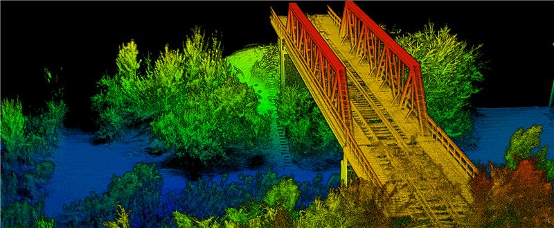
Survey Software Georeference raw lidar data
Georeferencer 2.5 featuring anyNAV software is suitable for survey applications. Users of Georeferencer 2.5 with the anyNAV feature enabled can boresight payloads and georeference lidar data using the user’s navigation data. The anyNAV software enables lidar surveyors to create accurate point clouds quickly. Georeferencer 2.5 now takes navigation data from third-party inertial navigation systems, which enables users to use that data to georeference raw lidar data from multiple sensor families. The resulting data can then be viewed in many point cloud viewer software packages. OxTS, oxts.com
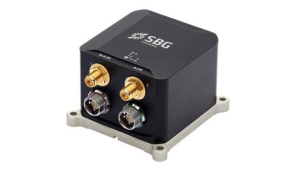
Inertial Navigation Solution Designed to deliver accuracy in challenging environments
Ekinox Micro combines a high-performance MEMS tactical inertial sensor with a quad-constellation, dual-antenna GNSS receiver, making it suitable for mission-critical applications. The device includes pre-configured motion profiles for land, air and marine applications, enabling the sensor and algorithms to be tuned for maximum performance in any condition. The device is designed for ease of use and integration, with simple connectors, a web configuration interface, datalogger, Ethernet connectivity, a PTP server, a REST API for configuration, and multiple input and output formats. Ekinox Micro is compatible with real-time kinematic (RTK) solutions and based on a tactical 0.8°/h class inertial measurement unit calibrated across the entire operating temperature range. It features accuracy roll/pitch of 0.015°, accuracy heading of 0.035°, and accuracy position of 1.2 m without any corrections or 1 cm in RTK. The device also meets the MIL-STD-461, MIL-STD-1275, and MIL-STD-810 standards. SBG Systems, sbg-systems.com
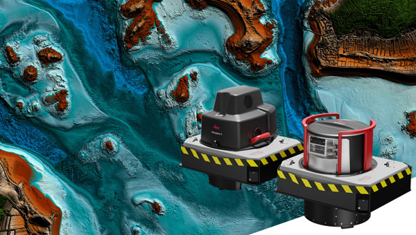
Lidar Sensor High-performance airborne bathymetric solution for deep water surveying
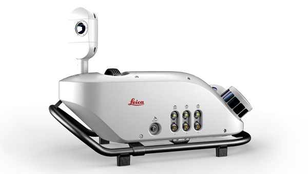
The HawkEye-5 increases survey efficiency by up to 25% compared to previous generations. The technology expands the capabilities of the Chiroptera-5 bathymetric lidar system, enhancing the productivity of applications such as nautical charting, environmental monitoring, and maritime surveillance in deep waters. The technology is designed to fit the Leica PAV100 gyro-stabilized mount, which isolates the sensor from unwanted aircraft movements — resulting in consistent data density and more efficient area coverage. The HawkEye-5 combined with the Chiroptera-5 features three lidar sensors, one four-band camera, and a QC camera to collect data from the seabed to land. Leica Geosystems, leica-geosystems.com
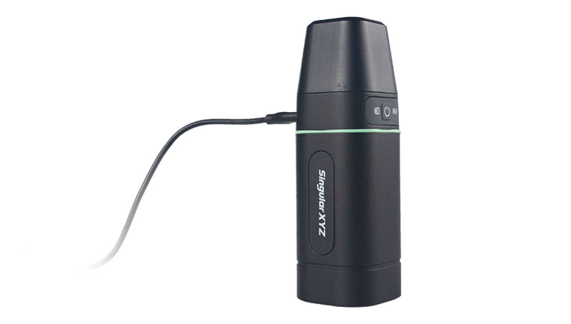
GNSS Receiver Complete with network RTK rover
The Sfaira One GNSS receiver is small and centimeter accurate. It provides users with an entry-level network real time kinematic (RTK) rover. Sfaira One is equipped with a GNSS module with 1,408 channels for GPS, BDS, GLONASS, Galileo and QZSS tracking — providing centimeter positioning in harsh environments. It also features advanced RTK and an anti-interference algorithm. The GNSS receiver connects via Bluetooth and can be configured to conduct surveying tasks on a smartphone. Additionally, Sfaira One supports SingularPad and SingularSurv software and is also compatible with mainstream field survey or GIS software. Sfaira One is IP65 dustproof and waterproof, which makes the receiver suitable for all weather conditions. It has a 4,800 mAh battery life with 16 hours working time and type-C interface that can be charged on-the-go with a power bank. SingularXYZ, singularxyz.com
MAPPING
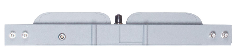
Mobile Mapping Solution Built for large-scale infrastructure measurement and digital twin creation
The Pegasus TRK100 is small and light, making it easy to mount on any vehicle. The mobile mapping system features the same modular hardware approach that enables users to add more cameras to expand the range of use cases. With its advanced mapping capabilities, the Pegasus TRK100 enables GIS professionals to visualize and understand the location of assets to help make the right decisions, improve asset management, and support infrastructure building and maintenance. The Pegasus TRK100 combines artificial intelligence and a learning algorithm to enhance and optimize the clarity of points in post-processing for improved accuracy. The versatility of the Pegasus TRK100 suits a variety of applications in diverse industries, including telecommunications, utilities and road maintenance. Leica Geosystems, leica-geosystems.com
OEM
Photo:
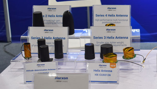
Helix Antenna Series Suitable for unmanned system applications
HX-CUX012A is designed with an extremely low profile, making it suitable for integration into UAVs, surveying and monitoring devices. It reduces the overall weight of applications, enables multipath mitigation and more. HX-CUX005A is a solution for integrated helix antenna applications. It is designed with the integration of a GNSS antenna and Bluetooth/Wi-Fi antenna, enabling communication and navigation without mutual interference. HX-CH7609A is a low profile and small size housed helix antenna. It has comprehensive GNSS support including GPS, GLONASS, Galileo, BeiDou, as well as L-band correction services. HX-CH7609A features centimeter phase center repeatability and high gain at a low elevation. With signal filtering and multipath rejection, it provides reliable and stable GNSS signals. HX-CHX600A is a high-performance helix antenna that receives GPS, Galileo, BeiDou, GLONASS, as well as L-band signals. With 4.2 dBi high gain, it provides suitable tracking performance at a low elevation angle. Its low noise figure design reduces transmission interference and improves signal quality. Harxon, en.harxon.com
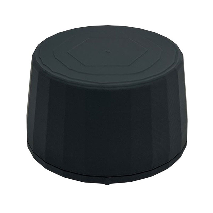
Helical Antenna Suitable for UAV applications
The HC990XF helical antenna is designed for precise positioning, covering the GPS/QZSS L1/L2/L5, QZSS L6, GLONASS G1/G2/G3, Galileo E1/E5a/E5b/E6, BeiDou B1/B2a/B2b/B3, and NavIC L5 frequency bands. This includes the satellite-based augmentation system (SBAS) available in the region of operation as well as L-band correction services. The HC990XF has a base diameter of 64 mm, is 37 mm tall and weighs 45 g. Its precision-tuned helical element provides full GNSS band coverage, suitable gain and axial ratio, and a tight phase center. The antenna base has an SMA (male) connector, three screw holes for secure attachment and an O-ring to waterproof the antenna connector. The HC990XF helical design does not require a ground plane, making it a suitable antenna for UAV applications. Tallysman Wireless, tallysman.com
Inertial Module For automotive uses
The ASM330LHB automotive-qualified MEMS inertial-sensing module provides accurate measurements for a wide variety of vehicle functions. With the dedicated software provided, ASM330LHB also addresses functional-safety applications up to ASIL B1. ASM330LHB contains a 3-axis digital accelerometer and 3-axis digital gyroscope that provides a six-channel synchronized output. The module’s high-accuracy inertial measurements are used to improve the precise positioning of a vehicle. The accelerometer and gyroscope maintain high stability over time and temperature, and have very low noise for an overall bias instability of 3°/hour. Specified over the extended temperature range, -40°C to 105°C, the ASM330LHB has multiple operating modes that let designers optimize the data-update rate and power consumption.
ASM330LHB can support advanced driver assistance systems or vehicle-to-everything communication, as well as help stabilize sensing systems such as radar, lidar and visual cameras, and assist semi-automated driving applications up to L2+. Additionally, ASM330LHB can be used to enable a variety of functionalities in the body of a vehicle. ASM330LHB was developed with the automotive functional-safety standard ISO 26262 — the ASIL B compatible software library has been certified independently by TÜV SÜD. By implementing dedicated safety mechanisms, including data integrity and accuracy, the library ensures compliance with ASIL B automotive systems.
With the companion software engine, the ASM330LHB supports the growing adoption of automotive systems that require safety integrity up to level B. The combination of two ASM330LHB sensor modules for fail-safe redundancy delivers resilient contextual data for driver-assistance applications such as lane centering, emergency braking, cruise assistance and semi-automated driving. ASM330LHB is AEC-Q100 qualified and in production now in a 2.5 mm x 3.0 mm 14-lead VFLGA package. STMicroelectronics, st.com
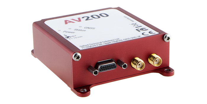
INS Built for automation applications
The AV200 is designed to give precise location data. It includes quad-constellation, dual-antenna, real-time kinematic (RTK) GNSS to provide users with position data as well as its temperature-calibrated, multi-core inertial measurement unit. These technologies give the AV200 position accuracy within 0.05 m, heading accuracy of 0.2°, and velocity accuracy of 0.2 km/h. The AV200 is built using the same technology that is commonly used for NCAP test validation, which has become the preferred technology for OEMs globally to test vehicles in both test-track and real-world scenarios. OxTS, oxts.com
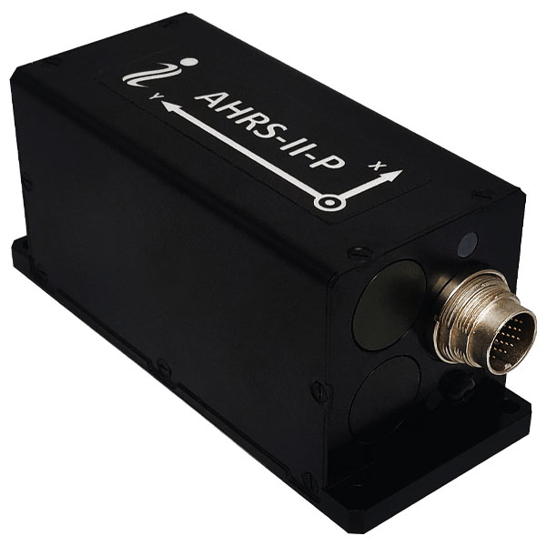
Reference System For attitude and heading
AHRS-II-P is an enhanced, high-performance strapdown system that determines absolute orientation (heading, pitch and roll) for any mounted device. The AHRS-II-P can determine orientation for both motionless and dynamic applications. The AHRS-II-P contains a tactical-grade inertial measurement unit (IMU) consisting of three high-precision MEMS accelerometers, three advanced MEMS gyroscopes and a high-precision, gyro-compensated, embedded fluxgate compass. It also uses 8 mm fluxgate magnetometers. This device is suitable for a variety of devices such as UAVs, antennas, ships and robotic devices.
Inertial Labs, inertiallabs.com
GNSS Receiver For accurate positioning and heading
As a high-precision integrated GNSS positioning and heading receiver, the A200 can track all existing and planned constellations — including GPS, BSD, GLONASS, Galileo, QZSS and SBAS — providing high-precision positioning and heading data for users. A200 is designed specifically for precision agriculture, machine control, fleet management, robot and other industries. The A200 is equipped with a K823 GNSS module. It also features 1,226 channels. The A200’s third generation IMU delivers fast initialization and ensures the output of heading during temporary GNSS signal loss. The built-in data link has low power consumption and a long working range. It also can be upgraded to a super-long-range data link module. ComNav Technology, comnavtech.com
GNSS researchers presented hundreds of papers at the 2022 Institute of Navigation (ION) GNSS+ conference, which took place Sept. 19–23, 2022 in Denver, Colorado, and virtually. The following four papers focused on autonomous applications in transportation. The papers are available here.
Addressing integrity monitoring of autonomous navigation
There are critical issues for the integrity monitoring of autonomous navigation applications, which include an adequate uncertainty budget in the observation domain, redundancy for the determination of the navigational states, and the capability of fault detection and exclusion.
Several aspects are addressed in the paper, including how to: determine interval bounds to handle GNSS multipath effects in urban environments, realize fault detection and exclusion based on constraint satisfaction and set membership, and improve the detector using weighting models.
The authors of the paper aim to contribute to the alternative integrity approach based on interval and set representations for bounding and propagating system uncertainty. Simulated and real-world experiments are carried out to demonstrate the feasibility of the authors’ proposed methods.
The authors note that statistical evaluation of integrity will not always suffice due to the presence of remaining systematic uncertainty, but state the alternative integrity approach will contribute to future autonomous navigation applications.
Su, Jingyao; Schön, Steffen; “Advances in Deterministic Approaches for Bounding Uncertainty and Integrity Monitoring of Autonomous Navigation.”
Estimation and reference systems in automation
For a high level of automation, estimation is crucial, and to achieve a full and reliable navigation evaluation, a trustable reference system needs to be developed.
Although the presence of a reference system and of an inertial measurement unit with GNSS through the multi-sensor fusion scheme was integrated, in GNSS-denied or challenging environment the navigation solution could not be accurately estimated and still needs to be fixed.
The authors of the paper propose new strategies to better estimate the lidar-based position uncertainty and to update the reference system.
The first strategy proposed involves determining the appropriate position error covariance matrix, based on the Hessian matrix and the scale of covariance obtained from a normal distribution transform (NDT) scan matching technique and the geometric dilution of precision computed from the distribution of point cloud segments in each scan.
In the second strategy proposed in the paper, the updated reference system was post-processed according to the loosely coupled INS/GNSS/NDT integration scheme with a forward and backward smoothing process.
The results of the proposed strategies indicated that the updated reference system provides more reliable navigation estimation compared to an existing reference system from commercial software and can be used for accurate evaluation of positioning, navigation and timing with automated vehicle applications.
Srinara, Surachet; Chiu, Yu-Ting; “Adaptive Covariance Estimation of Lidar-Based Positioning Error for Multi-Sensor Fusion Scheme with Autonomous Vehicular Navigation System.”
Evaluating TerraStar-X
GNSS performance using typical, low-cost GNSS devices in vehicles is not enough to achieve the positioning and availability needed for lane-level accuracy on autonomous vehicles. The antenna and receiver hardware available in standard vehicles limits the position accuracy and convergence performance. These limitations make the positioning more susceptible to error sources such as receiver multipath, noise, carrier tracking and stability.
GNSS correction services with additional design considerations and sophisticated algorithms are needed to work within the constraints of automotive-grade GNSS devices to achieve the performance required for lane-level positioning.
TerraStar X technology from NovAtel enables these applications. It includes an orbit and clock determination system (OCDS), which produces a set of corrections, precise satellite orbits and clocks, and satellite-specific biases for individual signals augmented by the computation of additional regional corrections.
The authors of the paper outline the design and performance of the combined OCDS and regional correction system. They demonstrate the performance of the TerraStar X technology across a variety of applications.
The addition of regional corrections enables automotive and mass-market applications to achieve in-lane positioning in seconds, using any dual-frequency, dual-constellation GNSS hardware. The result is software that provides a continuous stream of multi-constellation, multi-frequency GNSS corrections — enabling a correction service that makes the affordable GNSS device ecosystem possible.
Regional corrections also improve the performance of survey-grade GNSS receivers.
Mervart, Leos; Lukes, Zdenek; Alves, Paul; “TerraStar X Technology: Design of GNSS Corrections for Instantaneous Lane-Level Accuracy on Large Scale Connected Vehicles and Devices.”
Solving the localization problem in autonomous driving
The localization problem in autonomous driving imposes two criteria on the navigation solution: accuracy and reliability or integrity. According to the authors of this paper, solving the localization problem is a key requirement to enabling the development of autonomous platforms.
This paper presents AUTO, a real-time integrated navigation system that tightly integrates INS, GNSS-RTK, odometer, and multiple radars sensors with high-definition maps to achieve a high-rate, accurate, continuous, and reliable navigation solution. It also shows how AUTO leverages a tight integration of imaging radars with other traditional sensors to provide a robust navigation solution with corresponding estimates of the uncertainty.
The AUTO solution was tested in a variety of environments and locations, including a range of conditions such as winter weather, to assure the robustness and reliability required by autonomous applications.
The results demonstrate the lane level accuracy of the solution in a variety of challenging urban and downtown environments. Additionally, the tight integration enables the determination of protection levels to describe upper bounds on the uncertainty.
The results in the paper are illustrated using a Stanford Diagram, along with a user-defined alert limit to describe the solution integrity and availability. The proposed algorithm uses a map matching technique between the imaging radar data and a globally referenced high-definition map to better estimate the solution uncertainty and protection levels.
AUTO’s tightly integrated approach to integrity monitoring means uncertainties and protection levels can be determined even in areas where the system may experience extended periods of GNSS unavailability.
Krupity, Dylan; Chan, Billy; Ali, Abdelrahman; Salib, Abanob; Georgy, Jacques; Goodall, Christopher; “Integrity Monitoring and Uncertainty Estimation with AUTO’s Non-linear Integration of Multiple Imaging Radars and INS/GNSS for Autonomous Vehicles and Robots.”
A business-to-business, controlled-circulation magazine such as this one is a three-way partnership between the companies that support it by buying ads; the staff who write, edit and lay out the magazine’s editorial content, write a steady stream of posts for our website and digital newsletters, and sell advertising; and you, the readers, without whom we would not exist.
There are more than 30,000 of you who subscribe to the magazine (more than 17,000 to the print edition and more than 18,000 to the digital edition, with some overlap). Additionally, our website has about 97,000 unique monthly visitors, our e-newsletters have about 92,000 monthly subscribers, and we have about 46,000 social media followers. About 30% of you are in surveying and mapping, 18% in defense and government, 13% in professional and consumer OEM, and others in transportation, wireless/location-based services, distribution and resale, machine control and precision agriculture, and system design and testing.
You’re a large pool of knowledge, experience, and insight. I want to invite you to contribute to GPS World as sources, advisers and writers.
Perhaps you are a retired engineer with decades of experience designing receivers, antennas, or navigation systems and would like to share a few of the lessons you’ve learned. Perhaps you are a surveyor with a wish list of features for the next generation of rovers. Perhaps you are the manager of a port that uses GNSS to automate ship loading and unloading operations, or of a farm that relies on precision agriculture, and you have some observations worth sharing about your return on investment.
If you are a professor of engineering, you might want to bring to my attention a particularly promising student project. If you develop consumer products or positioning and navigation solutions for mass transit, or timing solutions for the financial sector, you might have interesting insights to share.
Alternatively, perhaps you would like to propose a question for our editorial advisory board, or a topic for the next installment of our “Authoritative Reference” series. Of course, occasionally you might also want to point out errors or omissions in one of our published articles or online posts. I welcome that feedback, too.
We already work with the marketing and media relations staff of our marketing partners, as well as public relations firms that represent GNSS/PNT companies. I always welcome their email messages and calls. This is not intended as an additional channel for them. I am also not setting up a discussion forum, because that would require content moderation and backend IT resources. Rather, I want to solicit comments, suggestions and interesting, useful content from people throughout the industry — some of which will guide or inspire my editorial choices and some of which I will publish.
We have limited room in print, but plenty online. Therefore, while I will occasionally work with the author of a particularly interesting or informative piece to generate an article for print publication, I will much more often choose articles, columns, and comments for online publication.
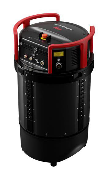
Leica Geosystems, part of Hexagon, has released the Leica CountryMapper for large-area imaging and lidar mapping. Combining a large-format photogrammetric camera with a high-performance lidar unit into a single system, the CountryMapper collects foundational geospatial data simultaneously to support a wide variety of user applications.
The CountryMapper combines imaging and lidar sensor modules into a highly efficient hybrid airborne system. The sensor features CMOS-based Leica MFC150 camera modules that leverage true mechanical forward-motion-compensation to deliver high image quality.
The sensor’s new Hyperion3 lidar unit features 60° field of view, improving the performance and flexibility of the system compared to previous lidar modules, while reduced laser divergence provides greater planimetric accuracy and better foliage penetration. The CountryMapper fully integrates with Leica HxMap multi-sensor end-to-end processing workflow, enabling distributed processing of images and point clouds to optimize productivity for very large data sets.
The CountryMapper supports applications such as orthophoto generation, terrain mapping, hydrography, forestry monitoring and infrastructure management. Users of previous-generation sensors can leverage their initial investment and upgrade their systems to the CountryMapper configuration.
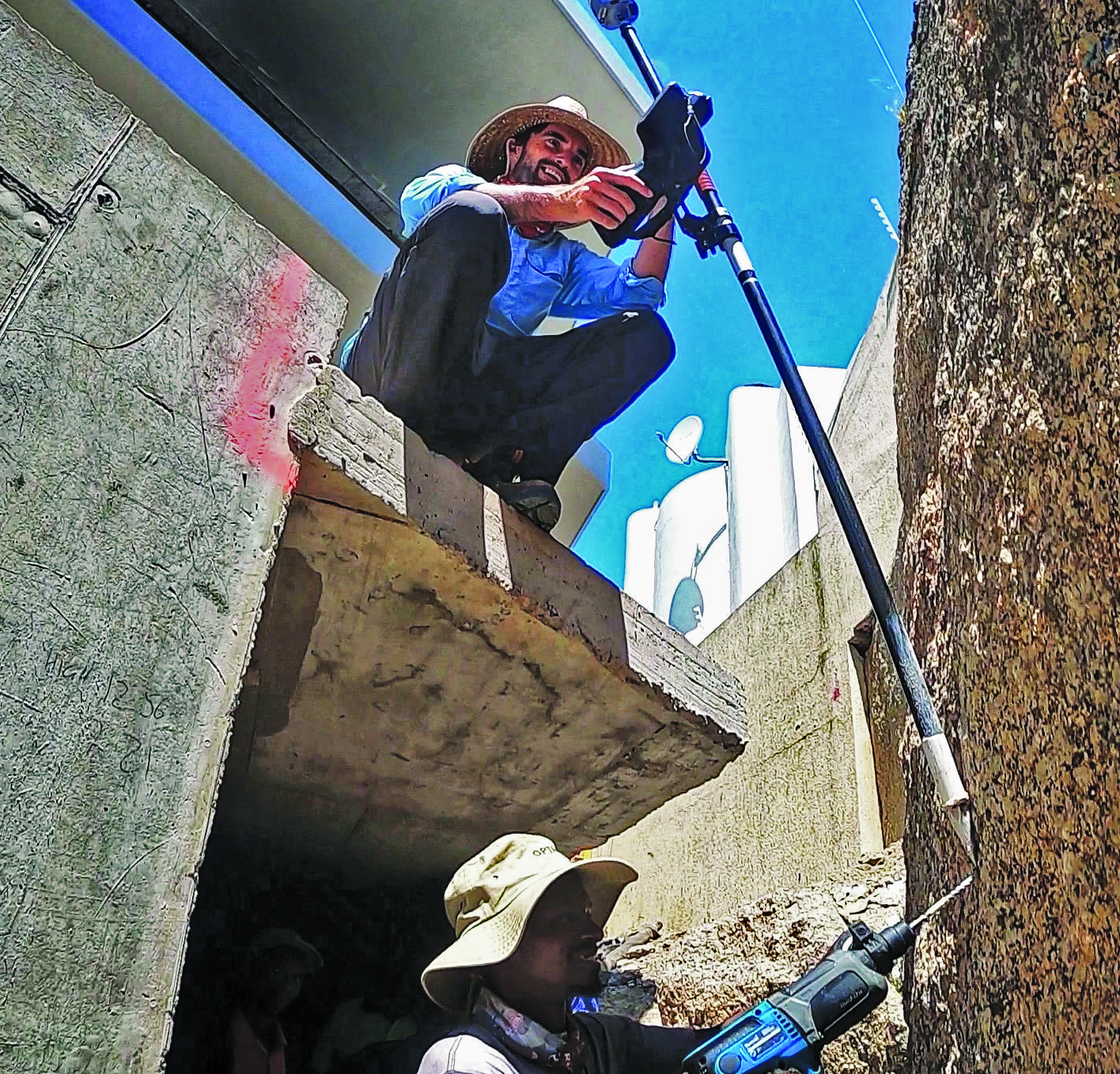
For tough shots in complex construction sites, Lee Landman says that tilt make impossible shots possible. (Image: Lee Landman)
Prior to the advent of tilt compensation for surveying and construction GNSS rovers, there were incremental approaches to tilt, with limited success. However, five years ago, “no-calibration tilt compensation” was first incorporated as a standard option for rovers. Some users remain skeptical or exercise the same caution as they did when such innovations as EDMs were first introduced. Nevertheless, the adoption of tilt compensation — for appropriate tasks — has spread rapidly. How did we get to this point?
For centuries, plumb bobs and bubbles were the only viable options to level an instrument or pole about a point. Early references to spirit levels appeared in the 15th century; however, siphon style water levels may have been in use in ancient Greece, China, and elsewhere for much longer. In more recent centuries, various types of level vials became a standard feature for surveying transits, theodolites and levels. Vials with a slight upward curve position a bubble between defined center marks when level.
Circular, convex glass bubbles appeared for industrial applications in the 19th century and were soon incorporated into surveying instruments and survey poles. In recent decades, electronic bubbles, or “e-bubbles” emerged, using microelectromechanical (MEMS) tilt sensors along with various methods to apply an orientation to compute the position of the pole tip relative to the phase center of the GNSS antenna. This is in contrast to relying on a bubble alone to orient the phase center directly above the pole tip.
There are both pitfalls and potential productivity losses if the pole has to be leveled solely with a bubble for each measurement; we’ll examine these later. If freed from the bubble — as electronic bubbles, tilt sensors, and various methods for orientation enable — how much productivity gain can be realized? For which tasks do the users find tilt compensation most useful? For which do they not? We talked with manufacturers, dealers and field users to find out.
Early adopters
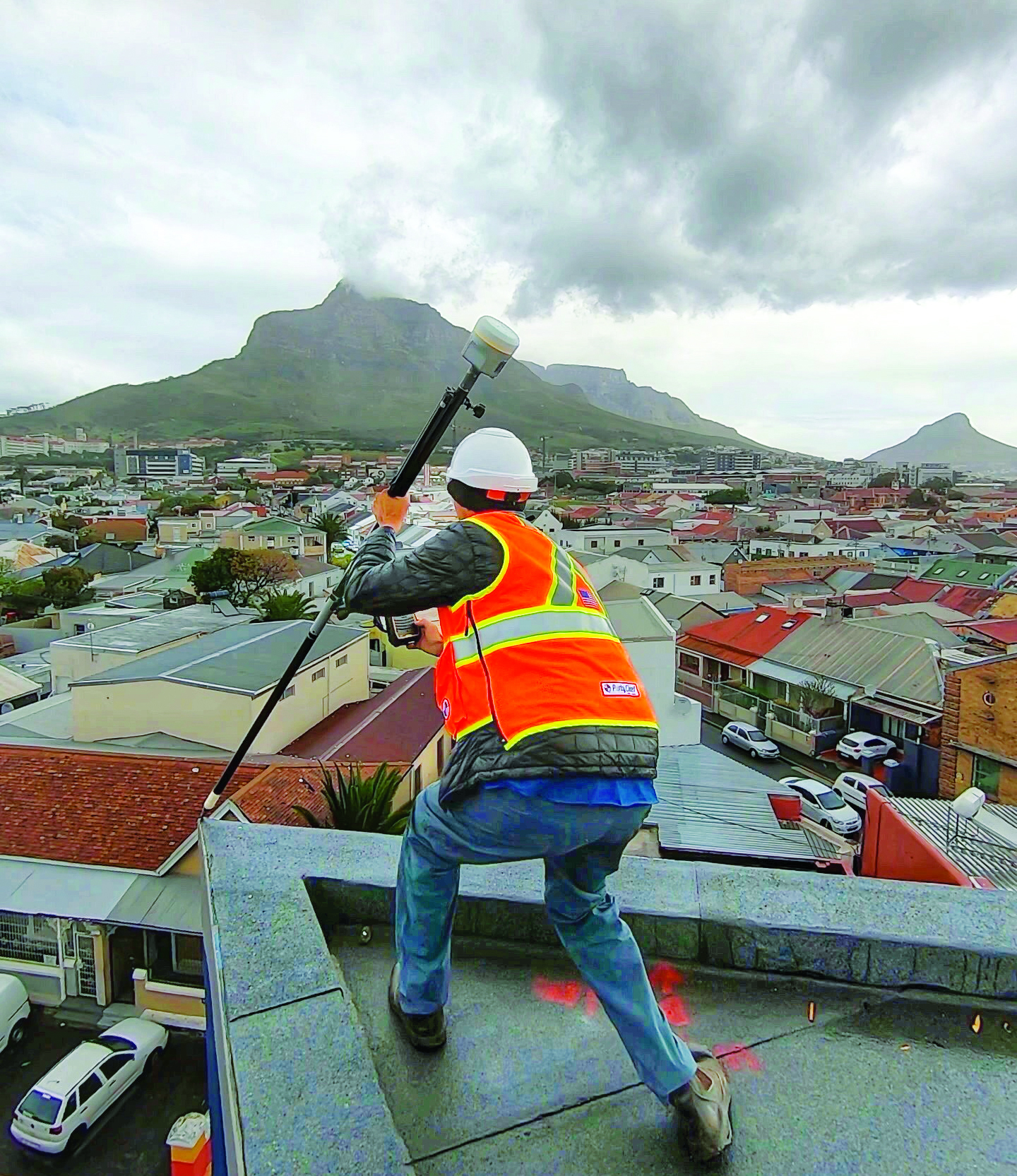
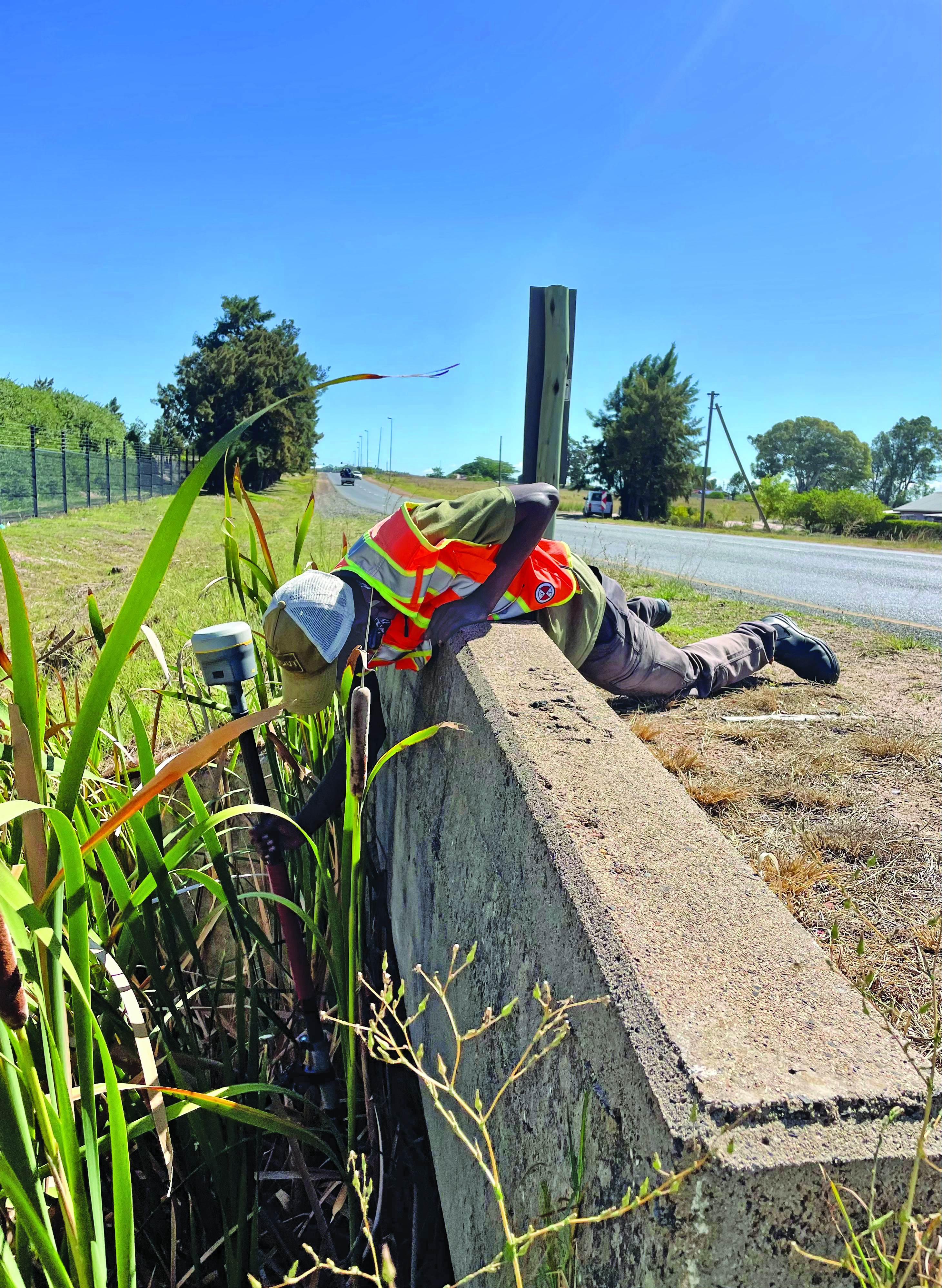
Tilt for safer surveying. (Image: Lee Landman)
Lee Landman owns a firm in the Cape Town area of South Africa that provides construction layout, civil engineering layout and related topographic mapping services. Landman obtained a Trimble R12i GNSS rover, with no-calibration tilt, shortly after its release in 2020.
“Tilt is my go-to tool for almost all tasks now, except layout that needs better than 15 mm to 20 mm tolerance,” Landman said. “For topographic mapping, I will get everything possible with tilt, and then use a total station to get the points I can’t with the rover.”
Landman reports productivity gains of 30% to 50% on certain jobs. His crews will try to leverage a tilt rover for as much of a job as they can, provided it meets precision needs. For checking work, such as grade checking or layout verification, they will try to use tilt for everything first. Then in any areas that look suspect, they will set up a total station to confirm. He said this saves a lot of time up front.
After several years of use, Landman said there are specific tasks where they will not use tilt, and we find this echoed by other users interviewed (and from my own tests). For instance, construction layout of such structures as walls and columns where a consistent 5 mm to 10 mm tolerance is required. He said the same applies for tasks where precise elevation is key, such as on road curbs and final road levels. However, he noted: “That’s a GNSS precision thing, not a tilt issue.”
Landman provides other caveats,“I am nervous using tilt on long rods or when you constantly change rod height, as the results of using a wrong rod height would be disastrous, and the deflection on long rods could also degrade the results.”
Summarizing the overall impact on his operations, Landman explained, “We have become more competitive. Not by sharpening our price, but by the fact that using tilt is less fatiguing and faster to do layout and data collection. That gives us an edge over firms that are not using it.” He provided the example of a foundation layout that needed 300-400 points laid out and chalked in an hour or two so that the excavators that were standing by could start digging as soon as possible. “It normally takes two to three moves of the pole and bubble checks to get a point on position without tilt,” Landman said. “Now, when you are doing 300 points, that is 600-900 times that I don’t have to look at the bubble and adjust the rod. The amount of energy and fatigue that saves is just outstanding. No sore lat muscles and eye fatigue.”
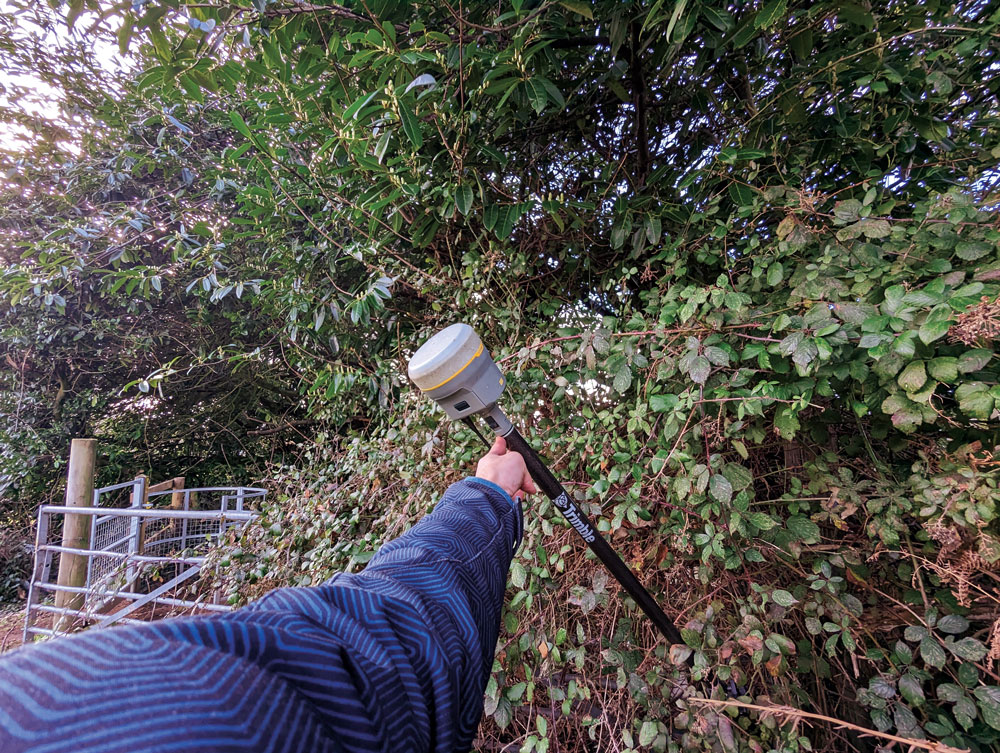
In the southwest of England, where Benchmark Surveys operates, fields and roadways are often lined with thick brambles, making if difficult to shoot features underneath them, such as utilities. James Richards of Benchmark says tilt has revolutionized the way they survey, enabling shots in places where even a total station (where the rod needs to be plumb) cannot take them. (Image: Benchmark Surveys)
Then there are shots that you cannot get with a bubble plumbed pole, Landman said. For instance, in checking rebar layouts prior to construction, as well as marking out on or below the steel rebar cages for plumbing points, voids and slab penetrations.
“Previously we could not easily do this, as you cannot get the pole plumb for total station shots or GNSS to place or check a point,” Landman said. “You just have to check positions on the steel for a column or wall to see if it has enough concrete cover or is in the right position prior to pouring concrete.”
James Richards is the survey manager for Benchmark Surveys, a family-owned and operated firm in the southwest of the UK that has steadily grown its portfolio of services. In part, this growth has resulted from their willingness to embrace new and emerging technologies. This included adding tilt compensated R12i rovers to their instrument inventory shortly after they became commercially available.
“We use tilt on every surveying task where we can use GNSS,” Richards said. “Tilt has enabled us to complete numerous jobs where we would have otherwise only been able to use a total station.” Apart from control, there are not many tasks for which Richards would not recommend using tilt, “It has helped improve our surveys. We can capture data quicker and easier than before and with greater accuracy.” Examples of daily challenges his crews face include getting shots in and around ditches, field boundaries, and boundary fences in foliage, and walls with foliage overhang. These are now easily captured using tilt.
“Tilt has had an enormous impact on our business. We complete work to a higher standard, capturing data quicker and easier,” said Richards. “It helps us capture data that was not possible without offsets. We’ve seen a rise in profitability since using tilt. Surveyors seem to be happier with day-to-day work, knowing that they can capture the data required to meet our high standards, and clients are also happier when receiving more data than expected from surveys.”
Stages of adoption
CHC Navigation is a GNSS developer and manufacturer that has sold hundreds of thousands of units over the past 15 years. They were quick to develop and implement tilt compensation technology, which has now become standard on all of their current models.
Rachel Wang, product manager of CHC Navigation’s Surveying and Engineering division explained the four stages they undertook in developing tilt.
“In the first stage,” said Wang, “users had to rely on the survey pole’s bubble to maintain a centered state, which had significant limitations in terms of measurement accuracy and accessibility.”
In addition to any GNSS error, there could be additional error due to a poorly calibrated bubble, a pole that is not straight, misalignments with each joint of telescoping rods, and user error in trying to keep the bubble lined up while simultaneously operating the field collector (if not using a bipod). Often it seemed that a surveyor would need extra hands and an extra set of eyes.
“The second stage introduced the first generation of tilt compensation using an electronic compass,” said Wang. “Although this technology enabled the first tilt measurements, it was hampered by problems such as low accuracy, tedious calibration, poor reliability, and susceptibility to interference from electrical currents or magnetic fields.”
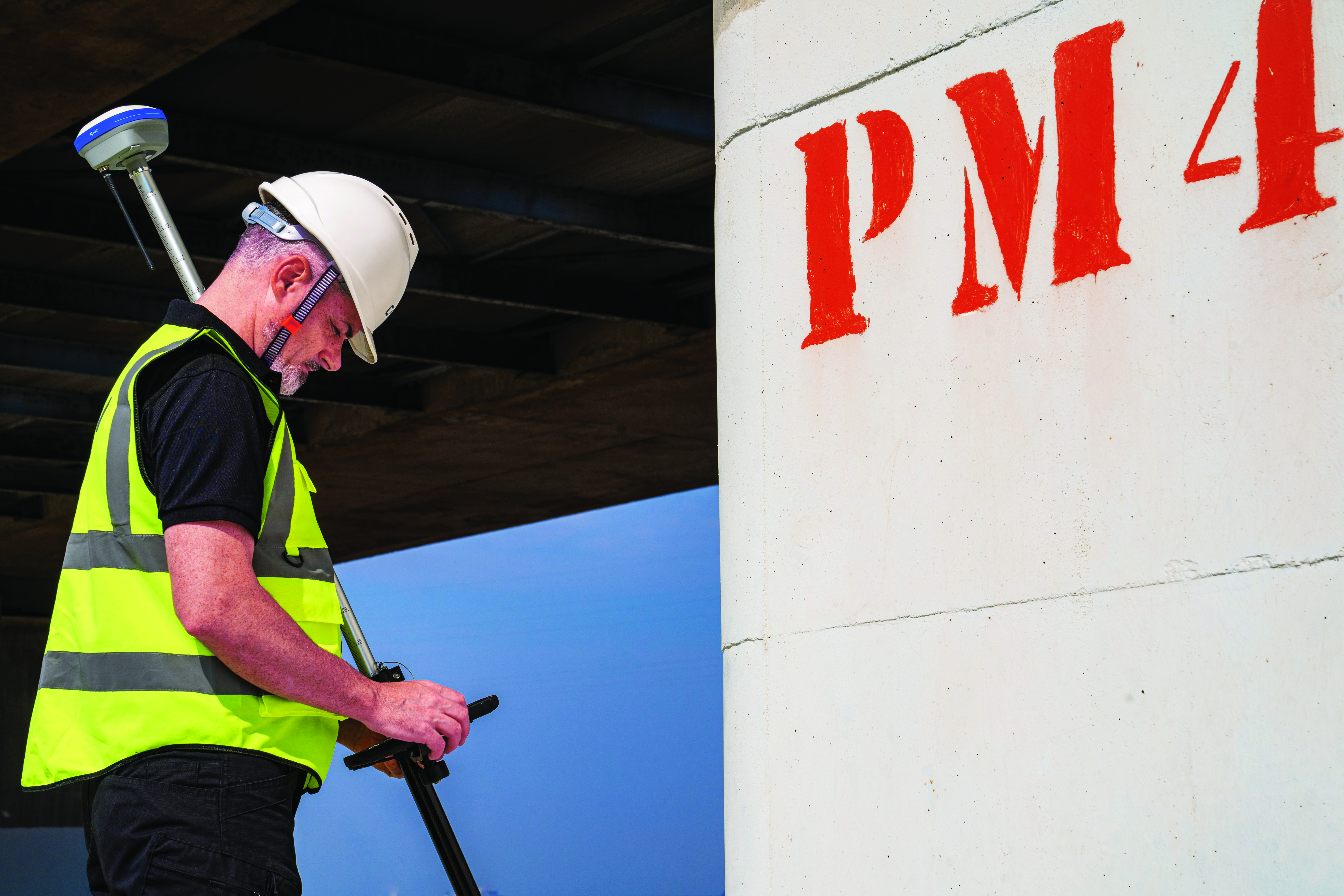
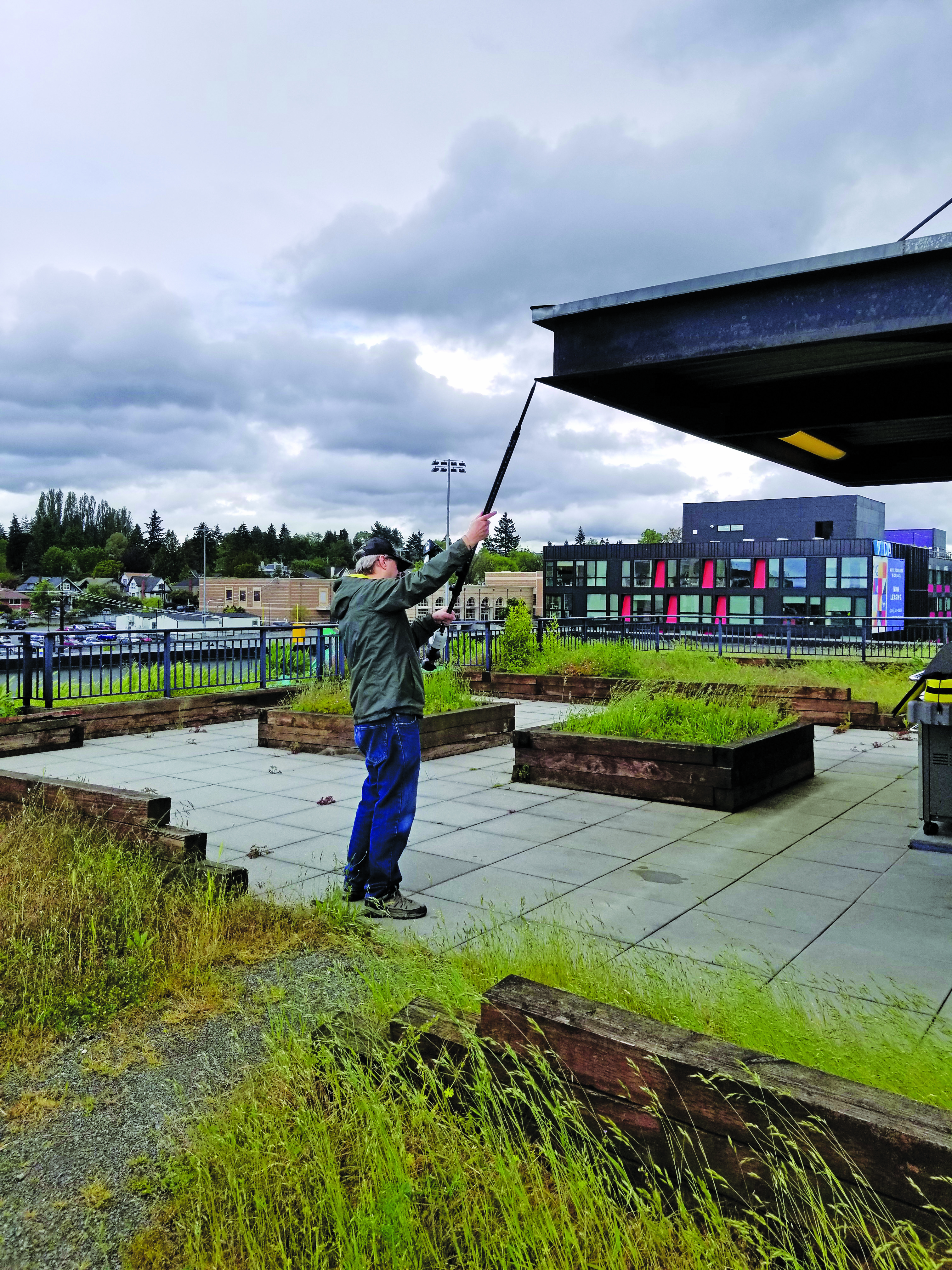
Common applications for tilt features include getting shots up against structures and improving sky view. For example, for this bridge column with sky partially obstructed by the bridge deck. (Image: CHCNAV)
Such magnetic oriented tilt compensation had been implemented on rovers several years prior to no-calibration methods, by manufacturers that included Javad, Trimble, Topcon, and others. The calibration step often involved rotating the rover vertically in eight or more horizontal positions. This was cumbersome, and the orientation quality changed over time, mostly unbeknownst to the user. It was no surprise that “mag tilt” never really caught on, and unfortunately it made some users wary of tilt in general, even when no-calibration solutions came along.
“The third step was the development of the second generation of tilt compensation, using hybrid positioning based on GNSS + IMU,” Wang said. “This technology was less affected by magnetic interference, but still required initialization of the IMU by shaking the survey pole.” I had tried several models from manufacturers of early “minimal calibration tilt” enabled rovers. For each, a certain amount of movement had to be induced on the pole, by walking around a bit, swinging the pole back and forth, or in a circular sweep. It often did not take more than a minute or so, and then normal moving around on the site would usually keep it calibrated. This was a tremendous step up compared to the old “mag tilt.”
“More recently, we are proud to announce the fourth step in our tilt measurement technology integrated into our new i93 GNSS RTK rover,” Wang said. “Our Auto-IMU technology further simplifies the IMU initialization process by observing acceleration at some point between startup and RTK operation. This replaces the previous repeated shaking of the survey pole for initialization. In fact, users can initialize the IMU while walking or moving normally. In addition, once initialized, the IMU feature is not easily lost even if the pole is carried on the shoulder, held horizontally, or even upside down.”
Wang said that all current CHC survey rovers are equipped with their newest tilt compensation technology. Since the international launch of their first CHCNAV GNSS RTK with IMU, the i90 GNSS in 2019, they have continued to incorporate this feature into all subsequent GNSS rovers. “Based on feedback from users, we know how valuable this feature is,” said Wang. “That is why we have made tilt compensation a standard feature on our current i73, i83, i90 and i93 models.”
Uptake
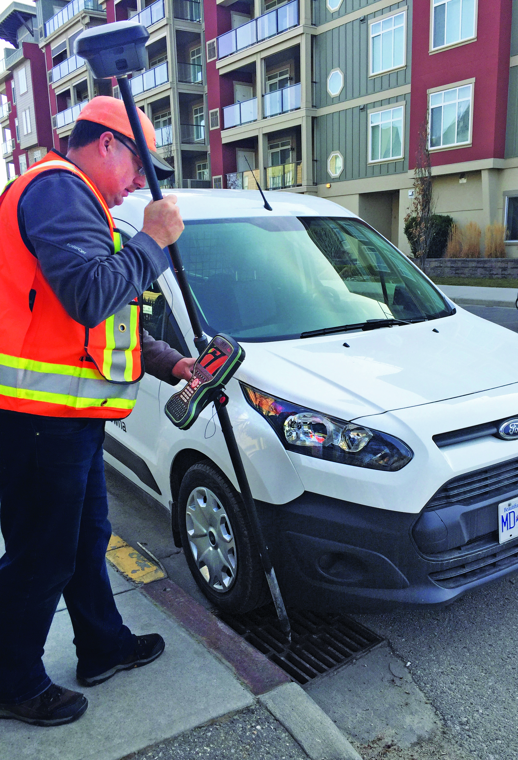
Greg Maier of the City of Kelowna, Canada, was an early adopter of tilt. He found it invaluable to access hard to reach features, such as this inlet under a car, and for safer surveying along the edges of roadways. (Image: Greg Maier)
For the past year, I’ve been talking to other GNSS manufacturers, their dealers, and customers, together with monitoring the subject in surveying and construction groups and forums online. Manufacturers have reported overwhelmingly positive feedback from dealers and customers about the tilt function. Typical feedback focuses on convenience and time savings of not having to level the pole manually.
“Based on our research, we have found this feature to be extremely useful for surveying and staking out on construction sites,” Wang said. “It has increased speed and efficiency by up to 30%.” I have heard similar statistics from each of the manufacturers contacted, as well as their dealers, and most of their customers that have used tilt.
There are common threads to much of the feedback from various sources: the tilt function is now an indispensable tool for many surveying applications.
As Wang noted, “While some users still prefer to use the traditional bubble to plumb the pole, we have seen a clear trend toward adoption of the tilt function in the field. The benefits of tilt, such as faster and easier surveying, are becoming more apparent to our users. As we continue to improve the accuracy of our tilt-compensation, we expect that more and more users will choose this convenient feature over other traditional GNSS rovers in the future.”
Another common observation (no pun intended): even if the pole-tilt feature offers significant convenience and time-saving benefits, it may not be the best option for tasks that require very high accuracy, such as surveying control points. For such tasks, manufacturers, dealers, and users recommend using the traditional bubble on a pole with a bi-pod mount for more accurate measurement.
As something completely new, the uptake across the surveying profession and for construction took time to grow. “It took quite a while to catch on here,” said Keith
Belsham, branch manager for Spatial Technologies, a measurement solutions dealer in the Vancouver region of British Columbia Canada. They specialize in solutions from Leica Geosystems and were an early provider of the Leica GS18 T, widely recognized as the first GNSS rover with no-calibration tilt.
“My perception is that in the United States and some other countries, there are more companies trying to stay at the top of technology,” Belsham said. “However, in our region surveyors are very cautious and need to do a lot of checks and look to see how others respond before they consider it. It was that way with other new technologies; I have memories of numerous total station demonstrations, when prism-less EDM’s were first coming out, where surveyors would pull out a tape measure to check whether the instrument was giving the correct distance.”
About three years after the introduction of no-calibration tilt is when Belsham said it really took off in his region, and it is now quite popular. He gave an example of a customer buying a Leica GS16 (no tilt), saying that they did not see a need for tilt, considering the extra expense. They then upgraded a week later once they were in the field and recognized many instances where the tilt would have saved them time.
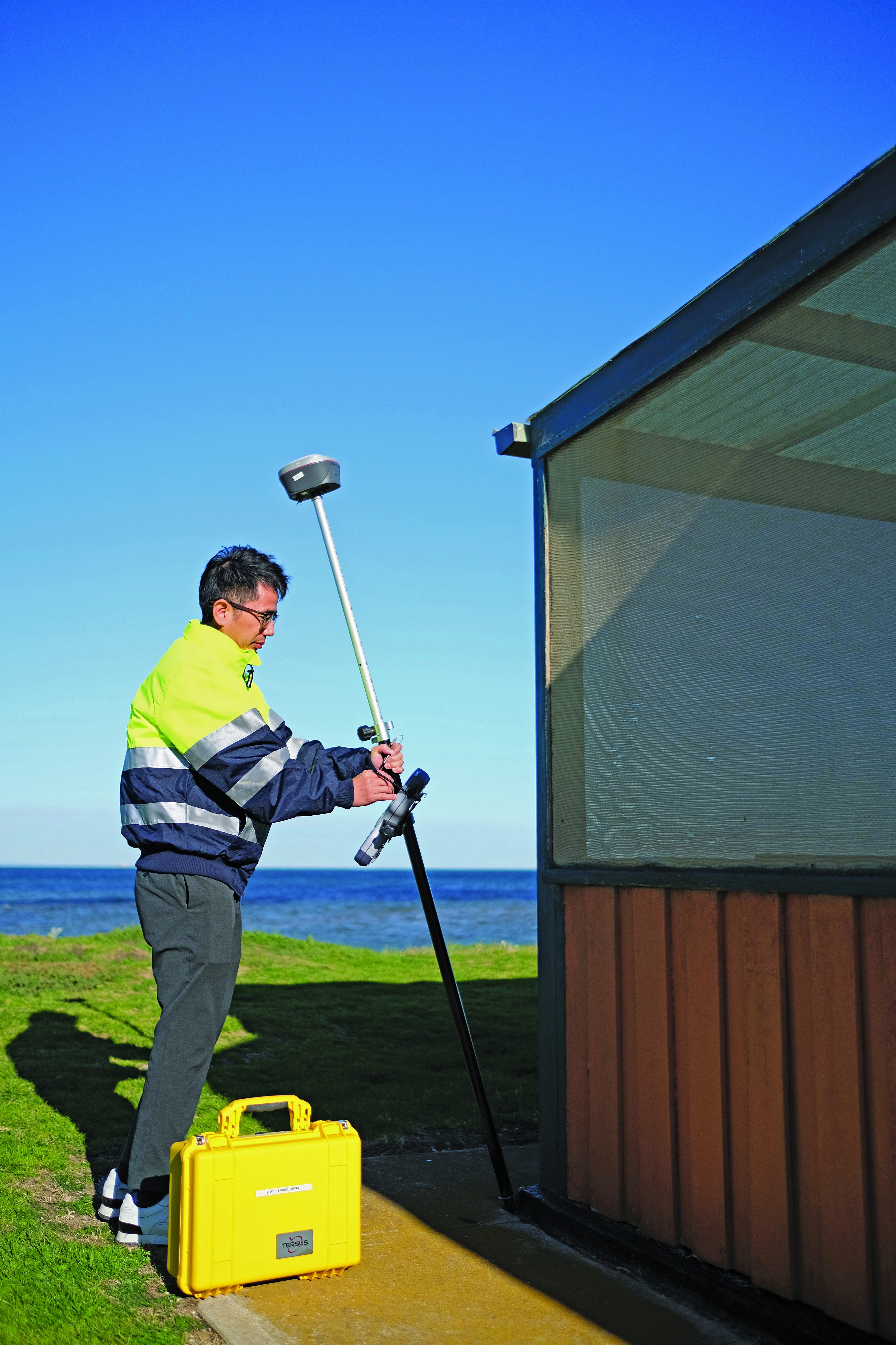
Rather than go the OEM route, Tersus GNSS developed its own GNSS board, positioning engines, and IMU tilt integration. (Image: Tersus GNSS)
A Spatial Technologies customer that has found tilt useful for numerous applications is Lucas Geomatics, a surveying firm based in Surrey B.C. “When I set up GNSS units for construction companies, tilt is great as they don’t have to be super accurate,” said Peter Smith. “I mean, here’s a machine with a bucket that’s 3 f wide, and the bucket is about an inch thick. The grade checked does not have to be super accurate for the machine to hit it, because end users in construction companies do not have to do precise surveying. They’re great guys who dig trenches and tilt gives them more than enough precision for their needs.”
Among the many uses Smith has found for tilt, he has also adapted it in a very creative way to deal with areas of deep foliage. A common approach to working in thick foliage is to raise the GNSS rover up on a tall or extended pole; this can increase the number of satellites viewed and reduce multipath. However, working with a bubble low enough on the pole to see makes it quite difficult to keep the rover at the top sufficiently still and plumbed over the tip. I remember some clever (albeit questionable) solutions folks cobbled together to help plumb very tall poles, such as a small live video camera pointing down over a bubble near the top of the pole to view on a phone. Smith said that tilt solved this problem, and he uses various tall rods, including one that extends to as much as 12 m. He chose a non-conducting pole, such as those used by utility companies for high foliage.
He does prefer to use the rover on a bipod, though, and bubble for control and points requiring very high precision. He sets the data collector software to log positions at 5 Hz or 10 Hz (standard in most systems) and has the software average multiple positions over the course of a minute or more.
Smith said that tilt has made a lot of difference in their surveys, especially where they want a lot of productivity, but do not need very high precision. Part of why he is impressed with the GS18 T is that they had upgraded from an older system, that only used two constellations, to full constellation support on their new rover.
Stability through motion
It sounds counter to one of the key principles for surveying measurement: the instrument and pole must be kept very still. However, in other data collection technologies, including aerial mapping and mobile mapping, leveraging predictable motion, acceleration, and trajectory caught on decades ago. There are numerous integrated GNSS + IMU solutions from, for instance, Applanix and NovAtel, that are the key positioning components for kinematic mapping systems. Such integrated sensor solutions are also in broad use now for UAV real-time and post-processing workflows.
One challenge for integration into survey rovers, was miniaturization. Additionally, such solutions needed a wealth of satellites and signals to be usable at tilted angles. The Galileo and BeiDou constellations reached full complement at about the same time as no-calibration tilt was introduced. Some manufacturers even integrated new antenna designs to better utilize satellites at tilted angles, for example in the Leica GS18 T.
The electronic bubble aspect of such solutions was in some ways the easiest to achieve. Depending on the quality of components, multiple tilt sensors can measure the angle of tilt at precisions matching, or even bettering that of typical pole bubbles. Plus, they are built into the rover boards with a direct relationship to the axis and phase center, whereas the bubble is external, down on the pole.
Integrated IMUs, with as many as nine axes, are highly sensitive, as are accelerometers (if an integration utilizes those). Skeptics always point out that IMUs are subject to drifting over time. However, the observed high-rate GNSS positions and motion sensors are continuously updating the calibration of the IMU. It is true of no-calibration tilt systems that if you hold the pole still too long, it will lose its calibration. Or if you move it too fast. Though on every tilt rover I’ve tried, I moved it around vigorously and spun it (more than would happen in normal operations) and it still kept its calibration. There can also be instances of environments with excessive multipath hazards — such as heavily wooded areas, urban canyons, or congested construction sites — where users often find it best to turn off the tilt for certain shots.
Industry penetration
Tilt for shooting inverts. (Image: Lee Landman)
While manufacturers have approached the GNSS/IMU solution in varied ways, the fundamentals are the same. Once some of the major vendors developed and integrated tilt, they began offering this feature for OEM customers, and in recent years we see tilt on many other brands worldwide. There are relatively new players in the market that took a different approach, developing not only their own GNSS boards and positioning engines, but IMU solutions as well.
Tersus GNSS has rapidly gained a presence in various global markets, though relatively new in North America. While starting as an OEM, the company pivoted to developing its own boards in 2015, and GNSS + IMU integrations more recently. It recently published a paper about what they call its “Extreme RTK Solution” that has a section with data from their own tests for both plumbed and tilted observations.
I did some quick tests with a Tersus Oscar Ultimate, at various angles of tilt, and in mixed environments. The results aligned closely with those in the paper, as did tests with other tilt rovers. I have had the opportunity to try rovers of several different brands, to check precision at various tilt angles against points established with static observations (to see how much the tilt added to the total error). While these were not comprehensive tests, I did compare notes with surveyors who did their own tests, and we’ve all been finding out the practical limits of tilt. Perhaps part of why tilt took a while to catch on was that surveyors needed some time with these units in real-world environments, to get a feel for sweet spots for tilt for different tasks that have specified error budgets.
To get an idea of potential productivity gains, I did a small topographic survey of an area I had previously surveyed with a conventional rover, total station, and scanner. The total station and tilt-less GNSS took about the same amount of time — but with tilt it took about half the time. Many variables can and do come into play, but the figure I keep hearing of up to 30% efficiency gain for many applications seems realistic. Certainly, for asset and resource mapping, tilt could easily fit the looser precision requirements.
As for degradation at various angles of tilt, checks against static points (beyond standard GNSS error) showed negligible differences under 5°, 1 cm up to 15°, 2 cm or more around 45°, and 3 cm or more at 60°. This was just a cursory look, and indeed any surveyors that use tilt should do their own testing. I did notice in the data that when doing simple topo shots, just moving around the site, the pole did not often exceed 5°. Therefore, moving around quickly and efficiently for topo, not having to look at the bubble, improves productivity without significantly compromising quality.
Layout, as surveyors and construction folks who use tilt say, can be quite a snap compared to the old “plumb-shoot, move-plumb-shoot, move-again-plumb-shoot, etc.,” process. You simply move the tip of the pole around until you are on the point.
Enabling further sensor integration
Tilt compensation has now extended to non-GNSS tech, for instance Leica Geosystems AP20 prism poles (used with robotic total stations). (Image: Gavin Schrock)
No-calibration tilt, and multi-constellation GNSS, have enabled further developments that may not have been practical otherwise. Leica has since added an image point extraction feature to its GS18I. This marries the tilt and a camera with a clear path to processing the images in the data collector software. With tilt running, and at ranges under 6 meters, you can roughly aim the camera side of the rover toward say, features under an overhang, that you would not otherwise be able to shoot with a GNSS alone. You walk past the features as the camera takes a series of images. Then, in the software, you identify the points in multiple images and photogrammetrically it gives the offset. You can also process the image series into point clouds. There were several attempts at this sort of solution in the past by various brands. However, without tilt it was too cumbersome as you would need to stop and plum for each image in the series. As one user told me, the new image point features are “like having a UAV on a pole.”
Tersus GNSS has taken a slightly different approach to their image point solution. You pick the point you desire in the camera view on the data collector, and then move along as the software automatically identifies the same point in subsequent frames, until it has enough matches from multiple angles to calculate the offset. CHC Navigation has just announced its own image point feature, with a two-camera integration in the i93 Visual GNSS RTK rover.
Pole tilt also has been integrated into non-GNSS solutions. For instance, the recent release of a prism-pole tilt solution by Leica, the AP20. A constant stream of positions of the prism, from the total station, takes the place of GNSS in this application. They’ve also included a rather clever automated pole-height feature.
What could be next? Perhaps small solid state lidars on rovers, or combined lidar/camera solutions such as on an iPhone/iPad, or a tiny SLAM scanner (that could also aid in position stabilization)? Not to mention what might be coming in the not-too-distant future in the realm of quantum sensing.
In considering all feedback about no-calibration tilt, it seems it is very much here and here to stay. There are many who love it and try to use it for everything (perhaps, in some cases, too many tasks). For others, it is conditional love: use where appropriate. While others still hate it immediately, perhaps on principle, though I find those folks typically have never tried it. Legacy tools and methods provide comfort and known levels of risk. New features such as tilt, provided some time is spent gauging its performance and appropriateness for various tasks, can deliver productivity gains that should prompt reevaluation of some long-held assumptions.
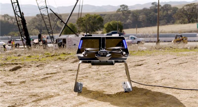
The Japan Civil Aviation Bureau (JCAB) has granted Skydio nationwide approval to remotely fly UAVs beyond visual line of sight (BVLOS). The approval enables streamlined BVLOS operations using Skydio Dock and Remote Ops.
Skydio’s artificial intelligence and autonomous technology enables UAVs to safely fly missions near structures in a way that would be difficult or impossible with manually-operated UAVs — even when operated remotely without a pilot on-site.
Under the JCAB approval, there is no requirement to use additional crew members, such as visual observers, or technology to detect crewed aircraft — eliminating some of the challenges faced by UAV operators. The BVLOS approval applies across Japan.
Notification of the flight area is required prior to takeoff using JCAB’s web portal. Operators can now remotely inspect critical infrastructure — buildings, roads, power plants and the scenes of natural disasters — safely and quickly without placing people at risk.
Trimble has released the X9 3D laser scanning system — a versatile reality capture solution suitable for surveying, construction and engineering users. The X9 is designed to enhance performance in more environments while leveraging Trimble’s X-Drive technology for automatic instrument calibration, survey-grade self-leveling and laser pointer for georeferencing.
The X9 expands on Trimble’s X7, delivering longer range, higher accuracy, shorter scan times and sensitivity, improving scan results. Advanced processing and a high-performance laser increase the sensitivity of all scans, enabling the X9 to capture difficult dark or reflective surfaces. A new center unit design also improves signal transmission for better scan quality.
The X9 provides accurate and dependable data, enabling confident decision making both in the field and in the office through in-field registration with Trimble Perspective and FieldLink software by minimizing the need for target deployment. The auto-calibration eliminates the need for annual calibration.
In addition, the X9 includes survey-grade self-leveling with the industry’s widest compensation range for fast, easy setup.
The X9 data can be delivered directly from the Perspective or FieldLink software to Trimble’s office software — including the Realworks 3D scanning software — business center office software, SketchUp and Tekla, or exported to industry-standard formats to produce application-specific deliverables.
It has been a wild decade, with so many players in the autonomous vehicle (AV) market, all striving for a leg up. Until the dominant design of present AV stacks emerged, there was no small amount of experimentation and less-than-successful alternate approaches. For instance, there was one big-name player that initially sought to create an AV solution without GNSS. Reality set in, and they soon embraced GNSS as an essential component.
Gordon Heidinger, segment manager, automotive and safety critical systems at Hexagon’s Autonomy and Positioning division, has had a front-row seat from which to observe, and contribute to the evolution of AV.
“I’ve been in the automotive industry for 20 years, all the way from OEMs like Chrysler to tier ones like Harman,” Heidinger said. “I’ve worked on the engineering side, on the project management side, and have now joined Hexagon | NovAtel to help further their involvement in the automotive industry. NovAtel was there for aviation 20 years ago, helping develop systems for planes to take off and land autonomously — we have a deep bench when it comes to applying such expertise for vehicular autonomy.”
NovAtel has long provided GNSS and IMU products and solutions, as well as real-time positioning services. Each are key elements of AV sensor stacks and overall autonomy solutions. Parent company Hexagon has multiple divisions contributing to intelligent transportation — on both the front end and back end.
The Front End
AV systems require highly reliable and smart sensor stacks that typically include cameras, radar, lidar and sonic sensors; these provide the relative positioning for advanced driver assistance systems (ADAS), which are becoming commonplace for newer vehicles. There are also implementations that include GNSS/IMU for navigation and lane keeping.
“Lane keeping is possible to a limited degree with combinations of the other sensors; however, you need GNSS to let you know where you truly are for autonomous driving,” Heidinger said. “Are you on the right freeway lane in Ottawa, or is this an exit ramp? This was a big problem with today’s simple single frequency solution; a car can assume highway speeds on an exit ramp, not realizing it was an exit ramp.”
Only with the absolute precise positioning that GNSS provides, and a high-definition map, level 4 autonomy — and potentially level 5 someday — could be achieved. With current sensor stacks, when the car is moving, it can reliably detect the other cars moving in its vicinity. Furthermore, vehicle-to-vehicle (V2V) solutions are being developed and tested, which enable a vehicle to share data about where it is going, its speed and acceleration, and its current location. We may remain far from full autonomy until such solutions are broadly deployed, however we will see some of the vehicle-to-everything (V2X) solutions sooner than later.
Various developers and departments of transportation around the world are testing short range V2X communication systems.
“We would need real-time construction zone updates,” Heidinger said. “It would be tough to do lane keeping if a construction site closes or diverts lanes during the course of a day. Or if cameras detect crashes, or blocked lanes, this will need to be broadcast immediately and continuously in real-time.”
A representative example of a production high precision positioning system was demonstrated at the recent Consumer Electronics Show 2023 (CES 2023). ZF Friedrichshafen AG (ZF) has developed ProConnect — a dedicated short-range communication (DSRC) solution that enables positioning and communication for use in applications with roadside infrastructure, such as traffic lights. It can be scaled to include other over-the-air alerts that could include first responder vehicle proximity and construction site status. At CES, the GNSS positioning was demonstrated with an autonomous vehicle platform from Hexagon.
“The precise map and the real-time updates from V2V and V2X systems all need precise absolute positions to relate objects to each other,” Heidinger stated. The question then becomes “…how reliable and trustworthy is that solution”?
There are international automotive-grade requirements such as the ISO 26262 standard for electrical/electronic systems, and automotive safety integrity levels. For instance, ASIL-B(D), and cybersecurity standard ISO/SAE 21434. The latter provides protection against external access without authorization.
“The level of reliability required is extremely high,” Heidinger said. “After all, these are human lives, in metal boxes hurtling along at highways speeds. There are ASIL standards that call for a probability of 10-8, or 1 in 100 million, in an hour that the system is wrong. These levels of reliability need to apply to electronic components, communications, and the availability of the GNSS positioning solution to really automate any type of vehicles. You’ll encounter similar AV standard references to five-nines, or 99.999%.”
Positioning Services
Heidinger explained that for most aspects of autonomy, GNSS can be “good enough”, even just to a foot. However, uncorrected, GNSS can never meet even those needs — achieving an accuracy of a few meters at best. Then there is the matter of reliability. Augmentations like real-time kinematics (RTK) and precise point positioning (PPP) apply broadcast “correctors” that can yield centimeter positions. RTK is not practical for broad areas or highway and road networks as it requires dense infrastructure and two-way communication with the vehicle, which can introduce security challenges.
Solutions for autonomy are typically PPP. While there are many applications of PPP that use clock, orbit and ionospheric model data broadcast from geostationary L-band satellites, for applications such as surveying, mapping, maritime and agriculture, this would not meet the reliability requirements for AV. The Achilles heel of broadcast PPP is that the satellites are usually limited in number and positioned over the equator; the vehicle can often lose sight of these. Instead, PPP services, such as that provided by NovAtel and others, are tapped by vehicles via mobile internet connections; this means cellular networks. While cellular services can often meet reliability goals, there are still vast areas of highways where availability is sparse.
The other challenge for PPP is the convergence time needed to get reliable sub-foot precision.
“No one wants to wait five minutes or more for it to converge,” Heidinger said. “By processing data from semi-dense networks of reference receivers, our PPP can converge rapidly enough to be ready to roll as soon as you start driving.”
The Back End
A free-for-all of autonomy is not going to happen on highways and roads that are not precisely mapped and kept up to date.
“There are visions of crowd sourcing map updates from the sensors in cars,” Heidinger said.
Crowd-sourced data is not systematic enough, though, and could be inconsistent. After all, there are privacy considerations, and how many vehicle owners would be willing enough to participate?
There are numerous mapping and imaging “buggies” plying road and highway networks on an ongoing basis; this could provide a base layer. But how precise? The specific applications these mapping buggies support may not need high precision. And operators may not be willing to invest in high precision/accuracy. The precision of the 3D maps would need to be higher than the target range of the AV systems. The technology exists and is broadly used for various applications in the form of centimeter precision 3D mobile mapping — at highway speeds. Such systems with lidar scanners, cameras, and positioning solutions can include GNSS, IMU, wheel speed encoders, and SLAM lidar for enhanced position stabilization. An example is the Pegasus TRK from Hexagon | Leica Geosystems.
GNSS is the key component — the provider of precise absolute positioning. When people drive, they are the sensor stack, and they are (mostly) aware of the context of where they are and can see and hear what is going on around them. Before we can hand over the driving duties to machines, and fully accept any autonomous driving technology, it will not only need to be as smart and aware as humans, but much better and more aware than humans. Autonomy sensor stacks can tell a car what it is doing, and what other things are doing in its immediate vicinity, but without a precise map, and knowing precisely where it is in real-time, a car would be still tip-toeing around in a fog of uncertainty.
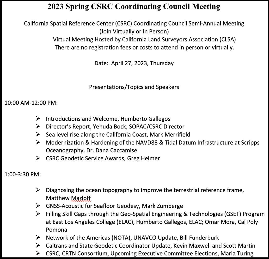
On April 27, I attended (virtually) the spring 2023 meeting of the California Spatial Reference Center (CSRC) coordinating council. See the agenda below. This column will highlight some activities with which the CSRS is involved and how it’s advancing the science of geodesy. Anyone who has been following my latest columns knows that I am an advocate for any person or organization that promotes the advancement of geodesy and recognizes that the United States is experiencing a geodetic crisis.
First, I would like to state that Yehuda Bock, the director of CSRS, has been instrumental in advancing accurate geodetic positioning for as long as I have known him. I first met Bock in 1978 while I was attending the Ohio State University.
A video of the meeting is available from the CSRC here.
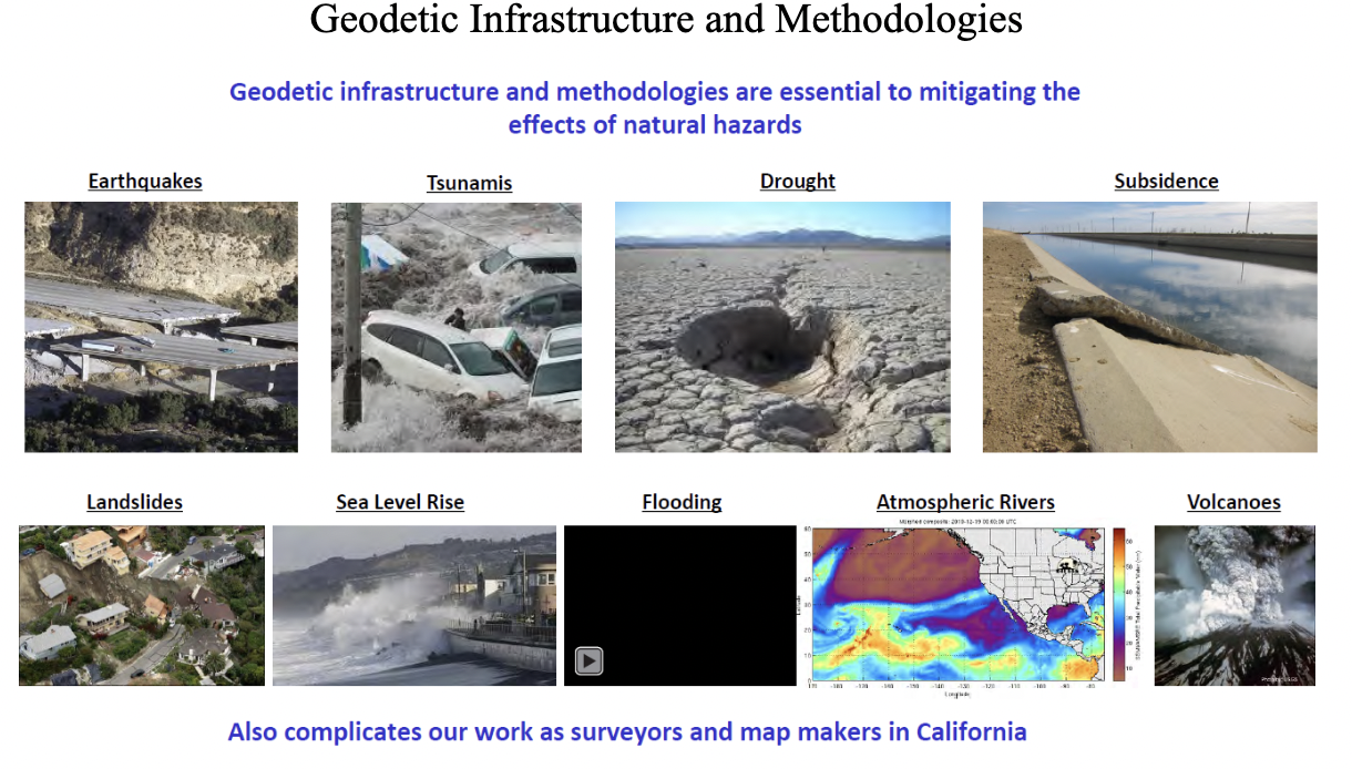
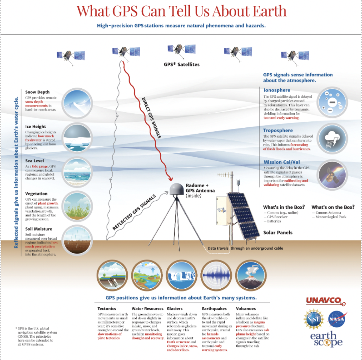
During the meeting, Bock presented the director’s report. He started with mentioning how geodetic infrastructure and methodologies are essential to mitigating the effects of natural hazards. That is something that affects everyone in the world, especially California, and one of the reasons that I always end my email messages and presentations with the following statement: “Geodesy is the foundation for all geospatial products and services.”
Geodetic infrastructure and methodologies. (Image: Yehuda Bock, Scripps Institution of Oceanography)
Bock highlighted how GNSS is important to explaining natural phenomena and hazards of the Earth. Most individuals use GNSS to know where they are on a map on a phone, but GNSS (and geodesy) is so much more important to the average citizen than just knowing their location on Earth. As you can see from the image below, GNSS positioning provides information about many of Earth’s systems, such as changes in local mean sea level, the values of atmospheric parameters, the status of water resources, and the movement of the Earth’s surface due to tectonic plates, glaciers, earthquakes and volcanoes. One or more of these activities are important to every individual in the world.
(Image: Yehuda Bock, Scripps Institution of Oceanography)
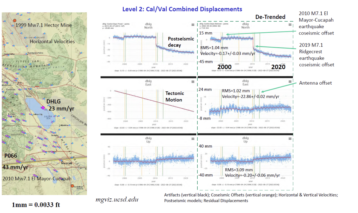
Bockprovided examples of how GNSS has been used to investigate and monitor earthquakes, which is extremely important in California. See the image below.
Displacement due to earthquakes. (Image: Yehuda Bock, Scripps Institution of Oceanography)
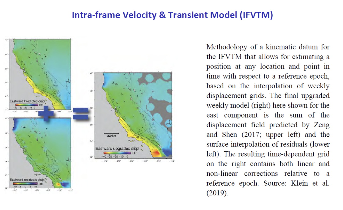
He highlighted a methodology of a kinematic datum that uses an intra-frame velocity model to estimate positions at any location and at anytime with respect to a reference frame and epoch.This concept is part of the National Geodetic Survey’s new, modernized, National Spatial Reference System (NSRS). Several of my previouscolumns have discussed NGS’NSRS and time-dependent coordinates (for example, see my August 2022column).
(Image: Yehuda Bock, Scripps Institution of Oceanography)
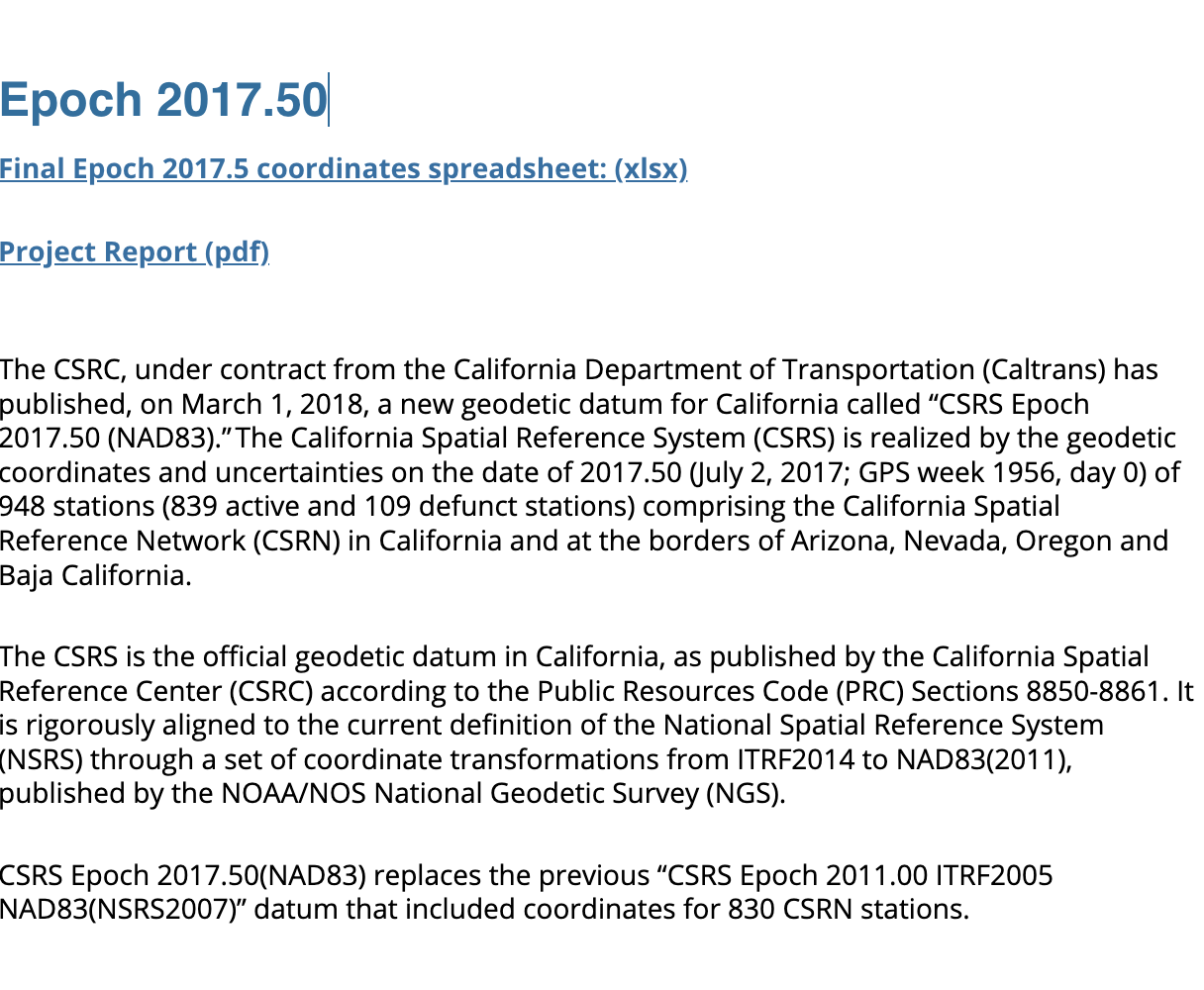
California’s geodetic network is significantly affected by crustal movement. To help address this issue, the CSRS updated the NAD 83 coordinates. It’s denoted as CSRS epoch 2017.5 (NAD 83). See the image below for the project report on the update. This is important to anyone surveying in California because of the crustal movement affecting the coordinates of the monuments. California is well positioned to implement NGS’ NSRS. Part of the implementation of the CSRC epoch 2017.50 (NAD 83) was to have the new epoch-date coordinates transmitted with RTCM 3.0 data streams. This is something that other RTN operators from around the nation will have to do after NGS publishes the NSRS coordinates. The CSRS is a model from which others can learn.
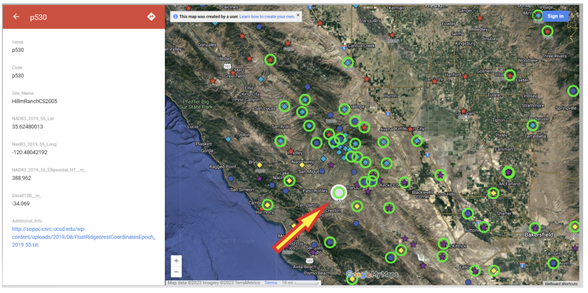
Users that access CSRC’sepoch 2017.50 website, can find thecoordinates of marks published in CSRC epoch 2017.50 (NAD83). See the image below for an example.
Mark p530 in CSRC epoch 2017.50 (NAD83). (Image: CSRC Website)
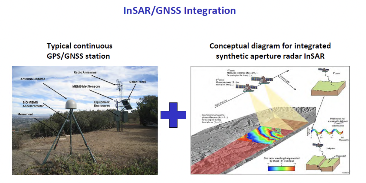
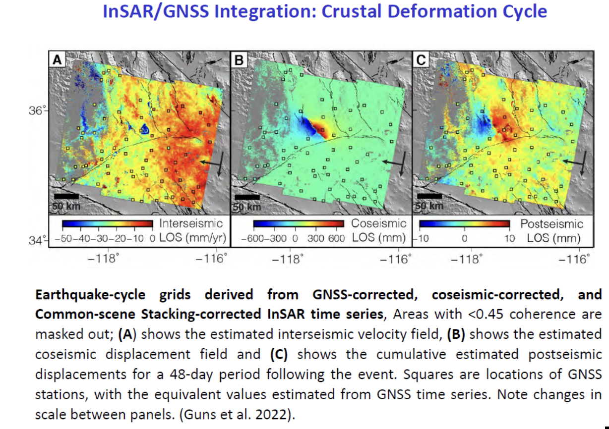
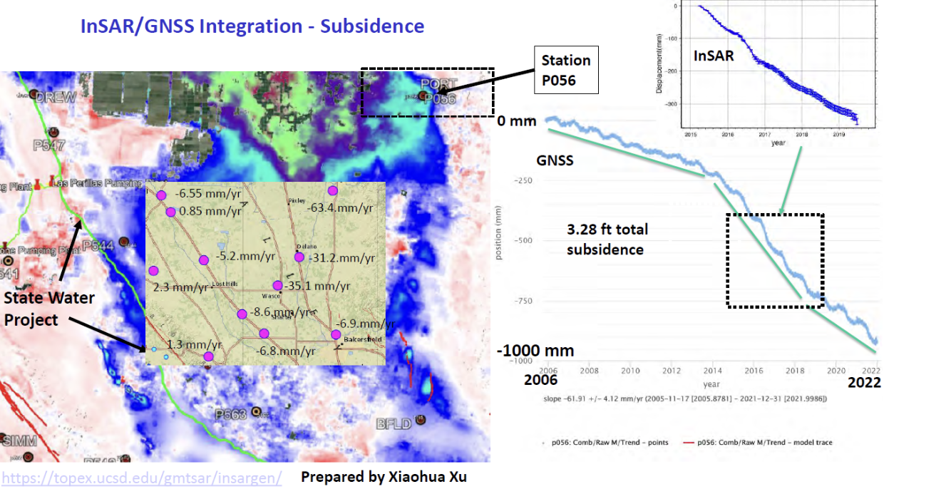
Bockdiscussed the integration of InSAR and GNSS to estimate accurateland changes over large areal extents. This type of research can help in developingan accurateintra–frame deformation model (IFDM) to account for movement between survey epoch coordinates (SEC) and reference epoch coordinates (REC). See my August 2022column for more on NGS’s definition of SEC and REC coordinates.
(Image: Yehuda Bock, Scripps Institution of Oceanography) (Image: Yehuda Bock, Scripps Institution of Oceanography)(Image: Yehuda Bock, Scripps Institution of Oceanography)
The rest of the director’s report included the following topics:
reference surfaces for unified reference frame
observation systems: terrestrial and marine geoids
unified reference frame
GNSS-IR
airborne gravity
geoid model
machine l;earning
tracking atmospheric rivers with GNSS meteorology
tracking extreme weather events with GNSS meteorology
cluster analysis to unsupervised analysis of GNSS time series isolate geophysical effects
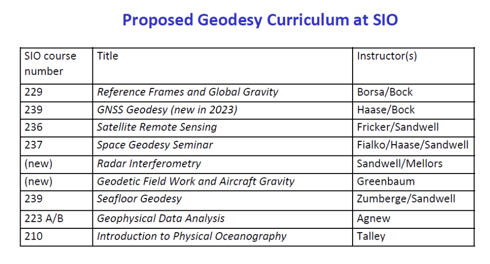
proposed geodesy curriculum at SIO.
The last one was the most important one to me because developing educational curriculums that include geodetic topics will help advance the science of geodesy.
(Image: Yehuda Bock, Scripps Institution of Oceanography)
Other speakers at the coordinating council meeting discussed the use of geodetic science in projects such as measuring sea level rise along the California coast as well as performing geodesy on the seafloor.
There was an interesting presentation by Humberto Gallegos discussing how to fill the skill gaps through the Geo-Spatial Engineering and Technologies (GSET) program at East Los Angeles College (ELAC). This program is helpful in developing future surveyors and geodesists.
(Image: EarthScope)
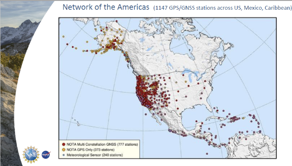
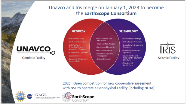
There also was a presentation on EarthScope by Bill Funderburk. See below for a few slides from Bill’s presentation. The presentation discussed the update on the Network of the Americas (NOTA). Bill provided information on NOTA partners, NOTA network and data, NOTA in California, and the EarthScope merger. His presentation also highlighted the many partners that support the NOTA, which includes 1,147 GPS/GNSS stations across the United States, Mexico and the Caribbean. Many individuals may not know it, but UNAVCO and IRIS merged on January 1, to become the EarthScope Consortium. Readers can find more information on this new organization here.
(Image: EarthScope)(Image: EarthScope)
I only highlighted a few items from the meeting. Please see the video of the meeting for more details.
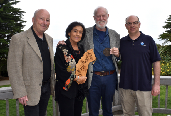
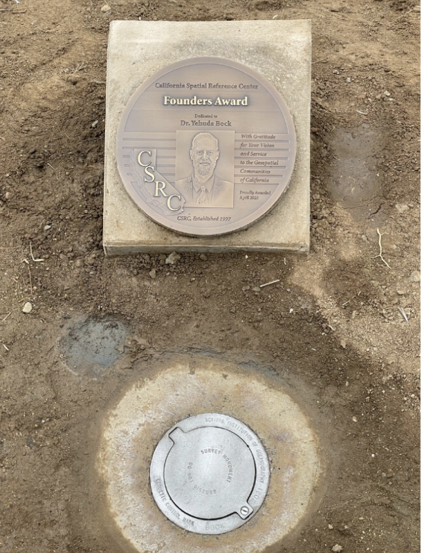
During the meeting, Bock was also presented with the CSRC Founders Award. It was a great honor for me to say a few words recognizing the important contributions that Bock has made to the geodetic community over the past five decades. It is in large part due to his leadership that California has progressed so much in geospatial positioning services. The following are a few photos from the ceremony and a statement from the CSRS.
Recognition Statement from the California Spatial Reference Center
“Distinguished Research Scientist, Yehuda Bock, was recognized by the California Spatial Reference Center (CSRC: http://sopac-csrc.ucsd.edu/index.php/csrc/) with the Founders Day Award. Presented by Dana Caccamise, Bock was honored for the “thriving science and community outreach facilitated through [his] vision and implementation of the Center for decades.” With Bock’s guidance, CSRC was established in 1997 as a partnership with surveyors, engineers, GIS professionals, the National Geodetic Survey (NGS), the California Department of Transportation (Caltrans), and the geodetic and geophysical communities, and has become of IGPP’s most successful outreach efforts.”
From left to right: Gregory Helmer, Sharona Benami, Yehuda Bock, Dana J Caccamise II (Image: Karissa Duran, Scripps Institution of Oceanography)The dedicated plaque and monument. (Image: Karissa Duran, Scripps Institution of Oceanography)
In my opinion, integrated and collaborative organizations are necessary for the successful development of geospatial products and services.
I would like to highlight how the Ohio State University is integrating geodesy in a geology program. The Ohio State University Geology Field Camp is a geology class that is held every year. This year, the OSU Geodetic Department is going to participate in the program to explain how the science of geodesy is helpful to geologists. The plan is to provide exercises to explain how the camp’s activities can be enhanced with geodetic techniques.
The 2023 geology summer field course lasts six weeks. This year, the course starts on Thursday, June 1, and ends on Friday, July 14. Students receive six semester credit hours for completion of the course.
The course emphasize the following:
observation of stratigraphic units and their characteristics
interpretation and synthesis of structures, paleoenvironments, and geologic history
presentation of results by means of geologic maps and cross-sections
experience with 3D visualization, GIS, GPS and computer analysis of field data
In conclusion, on June 22, NGS is hosting a webinar that will discuss some of the benefits and challenges of transitioning to the modernized NSRS. The presenters are not NGS employees. They are guest speakers from the geospatial community. I would encourage all users to register for this webinar.
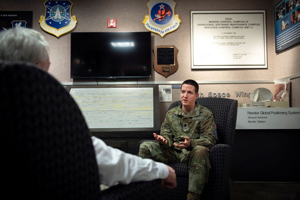
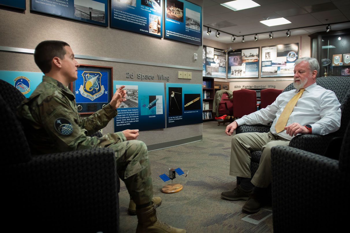
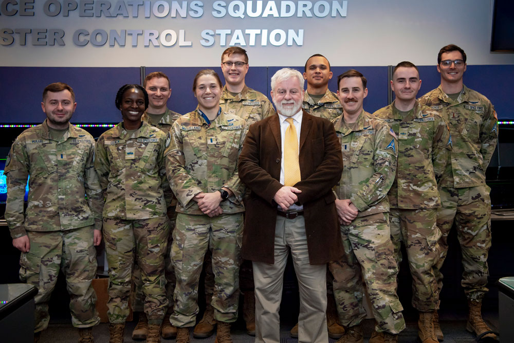
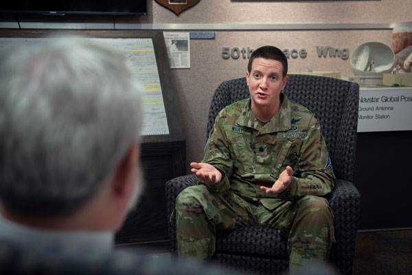
Exclusive interview with Lt. Col. Robert O. Wray, Commander 2nd Space Operations Squadron, Schriever Space Force Base, Colorado. Read more from this cover story here.
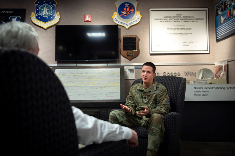
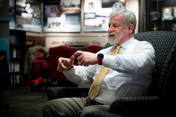
Matteo Luccio, GPS World’s editor-in-chief, had the opportunity to interview Lt. Col. Robert O. Wray, Commander, 2nd Space Operations Squadron, at Schriever Space Force Base, Colorado. (U.S. Space Force photo by Dennis Rogers)
The entire Global Positioning System constellation comprised of 38 satellites — with its billions of users and myriad military, commercial, consumer and scientific applications — is controlled from one room in a gray office building on a small military base about nine miles east of Colorado Springs, Colorado. The base is Schriever Space Force Base (SFB) and the room is the “operations floor” of the GPS Master Control Station (MCS). It is staffed by members of the 2nd Space Operations Squadron (2 SOPS), an active-duty unit of the U.S. Space Force, supplemented by members of the 19th Space Operations Squadron (19 SOPS), a unit of the U.S. Air Force Reserve. The two squadrons are known collectively as “Team Blackjack.”
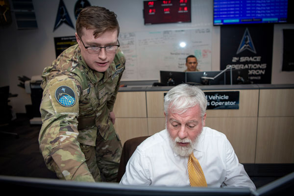
Lt. Col. Robert O. Wray is the commander of 2 SOPS and of those 19 SOPS members assigned to the MCS. On March 16, at Schriever SFB, Wray spoke with me at length about the training and duties of his team members, the challenges they face, and what brought him to his current assignment. He then gave me a tour of the MCS and introduced me to each of the 10 people on duty. At any given time, eight of these operators are military personnel and two are civilian contractors. They receive feeds from a worldwide network of monitor stations and ground antennas, including telemetry from the satellites, that enable them to precisely monitor the satellites’ orbits and the state of their systems. The operators upload data and commands to the satellites around the clock to keep the constellation fine-tuned and respond to changing circumstances.
Two of the eight uniformed personnel in the room constitute the GPS Warfighter Collaboration Cell (GWCC), a customer interface that responds to calls from U.S. and allied military forces, as well as private companies and others who need support with GPS operations. One call might be from a military unit needing a boost in the power of the GPS signal in their area during a strike, another might be from a shipping company investigating signal interference near a port, and yet another from a federal civilian agency testing equipment. GWCC is also in daily contact with the U.S. Coast Guard’s Navigation Center and the Federal Aviation Administration (FAA).
Below, you can read a transcript of my interview with Wray, edited for clarity.
How do you recruit and select your operators? What is their typical background?
We have both commissioned officers and enlisted operators and they come from different sources, different backgrounds, different degrees of education. Most of our enlisted operators are first assignment personnel, meaning that they enlist, normally when they turn 18; they go through a Space Force-specific version of basic military training down at Lackland Air Force Base — so, there’s an overarching Air Force training, and then there’s some specific Space Force training —then, they go to an undergraduate space training at Vandenberg Space Force Base in California; then, they will come here and receive specific technical training on how to do their duties at the Second Space Operations Squadron, operating our equipment.
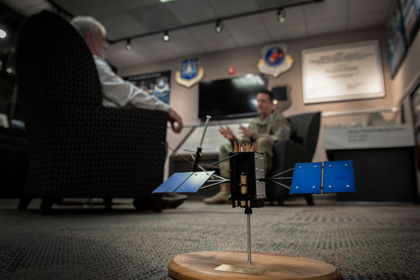
The 2nd Space Operations Squadron (2 SOPS) operates the GPS constellation around the clock, supplemented by members of the 19th Space Operations Squadron (19 SOPS). (U.S. Space Force photo by Dennis Rogers)
Our officers must go to college first, then they volunteer for specific career fields. Since the Space Force has been stood up, they can join it directly. They will say whether they would like to be a space operator or work on a different career field, such as cyberspace operations. In fact, for about 85% to 90% of my squadron’s personnel this is their first assignment. We can do that through all the training that we provide. We have one of the longer mission qualification training courses within the Space Force.
Roughly how long is the training for the enlisted personnel and for the officers?
For the enlisted personnel, there’s that undergraduate space training of about four months at Vandenberg. Then they come here and it’s 135 days for the enlisted training program. For the officers, we have a couple of different positions, so the training duration varies. On average, it’s about four months, ranging between three and six months; it just depends on their duties. My engineers have a six-month training course because they have more technical requirements. Some of my other officer positions might go through a three-month training course. Then, as they progress through their career here, they may go to back to an additional month-long training course, as their duties evolve, after they master their initial duties.
It’s interesting: for most of my engineers and operators, this is their first assignment and they get to choose the category of mission — such as operations versus cyber versus engineering — to establish their career field. However, they’re not given a list of units. So, most of these folks are just selected by the talent management office. They distribute talent based on people’s testing scores, backgrounds or, on the officer side, degrees, to make sure that we have a fair mix of personnel. I have a handful of personnel who were able to request 2 SOPS and those are mostly my senior management folks. They’ve completed a couple of assignments and are now coming back in a leadership position. For example, I requested this job. Then, I went before a board and it said, “Okay, based on your experience, your knowledge, and your interest, we’re going to assign you to the Second Space Operations Squadron.”
The 18 year-olds’ background is being teenagers, of course, but what is typically the officers’ background?
Most of our officers come in with STEM degrees. There are some exceptions. A STEM degree is not a prerequisite, because we will train you to the standard necessary to operate the GPS constellation, but most of them have degrees in that area. My engineers are required to have a bachelor’s degree in engineering — electrical engineering, mechanical engineering, aeronautical engineering — but for most other folks who come in, the Space Force leans very heavily toward STEM.
What key skills must your operators have?
Operating in space is complicated because we must consider orbital mechanics. So, you must be able to understand physics. In this job, just to understand how satellites work, you need to be able to absorb information quickly, because it’s always evolving as we get new capabilities. Our training days are long. To stay in this job, you must be able to retain a large volume of information and continue to progress the next day.
Not everyone does that. We do have people who just do not meet our training standards. So, we assign them to different types of jobs, not in the Second Space Operations Squadron. Not everyone graduates our training program. Once they graduate, however, we have very good retention rates. A typical assignment for operators is four years here, both for officers and for enlisted personnel. For our engineers and our other support personnel, it is a three-year assignment. So, those are locked down timelines, which build deep expertise and allow them to prepare future inbounds to take their place one day.
What do they spend most of the time doing?
Members of 2 SOPS, one member of 19 SOPS, and a visitor on the operations floor of the GPS Master Control Station. (U.S. Space Force photo by Tiana Williams)
We have a 10-member crew. There’s a crew commander, who is always an officer. Besides the technical acumen, these officers must be able to manage people and handle multiple anomalies going on at the same time, multiple different directives that we have coming in from different authorities, both civil requirements and military requirements. They need to know how to balance all of that and take care of the people and make sure that the missions are done in the correct priority order. So, there is a leadership element, besides knowing how to operate all the controls in the computer systems.
The crew commander manages the overall schedule. We have 38 satellites that we need to contact at least once a day, some of them more often than that. We have maintenance procedures. We have our ground infrastructure. So, deconflicting all those pieces and making sure there’s time to do all the different requirements is part of the commander’s overall job.
There is an enlisted crew chief as the senior enlisted position on the crew. That person’s job is to help with all the different reports we must submit, and then augment the crew commander. You have the satellite hardware that’s floating through space, and you want to make sure that the batteries and all the different components are operating correctly.
We have payload system operators, who assemble, correct and adjust the signal that we all receive and love that says what time it is and where you are on Earth. So, they are monitoring all the different monitoring systems we have around the world to say, “Yes, these signals are accurate.” And if there’s a slight deviation, then they identify it and say, “We need to contact the satellite and update the information on that.”
Earth is not a perfect sphere. So, as satellites go around, they drift due to the different pull from gravity. We have three vehicle system operators. These are junior enlisted positions; they are controlling the satellite hardware — mitigating effects from solar weather, ensuring that the satellite constellation is where it needs to be, performing all the different on-orbit type maintenance activities — and then they will receive direction from our engineers when we must maneuver the satellites.
We have two contracted positions. We have a network administration operator who is responsible for our ground infrastructure. Within the U.S. Space Force, there are two sets of ground infrastructure to control the satellites. We have our dedicated ground facilities to control the Global Positioning System and monitor it. We’re fortunate in that regard. So, we make sure those are operating properly and we have the correct communications. The other infrastructure is the U.S. Space Force’s Satellite Control Network, which we can share with other satellite constellations as a secondary system.
How often do you have to fire the boosters to adjust the position or trajectory of the GPS satellites?
Some satellites and some orbits are more problematic than others, due to the pull of gravity and other variables. We may have to fire the boosters on a satellite once every 12 months or only about 18 months. We plan those. Every now and then, a satellite might fail, or the atomic clocks might be shutting down and I have to move another satellite to replace its position in orbit. Those happen occasionally, maybe once every two years. And that can be a longer-term burn where the thrusters will burn longer and the satellite will drift for weeks at a time. All our satellites are loaded with plenty of fuel, so fuel has never been a limiting factor in the life of any of our satellites.
We’re fortunate that, as a whole, they have fairly stable orbits and that most of the corrections we can make from a very slight drift, we can correct with the signal that we transmit, as opposed to having to do many tiny maneuvers. When we do those tiny maneuvers, we then have to make that satellite not visible to users, because we are not able to correct in real time for its movements while it’s maneuvering so your calculation for you would be off, even during the second or two while it is maneuvering. That’s why we will correct with our signal to compensate for a very slight drift. Then when the drift gets closer to a meter, we will then maneuver it back into its optimal spot in its orbit.
What satellite telemetry do the operators monitor?
Besides the satellite’s location and orientation, we monitor such things as pressure on the solar panels, temperature and impact from radiation — not only from the Van Allen belts, but from any kind of solar activity.
What else do they monitor? For example, the health of the various systems, the battery charge, etc.
We have three formal missions: precision navigation, precision timing, and nuclear detection support. Each of the satellites has a nuclear detection payload. So, there’s plenty of different information they monitor relative to that, including our ability to cross-link that nuclear detection information between satellites. Are those systems operating optimally? We make sure that we downlink the information to the Air Force Technical Analysis Center, which receives all that and will receive a real-time nuclear detonation detection notification. While we control that system, we don’t receive that data. So, if there’s a nuclear detonation somewhere, that won’t show up on my screens. We make sure that the whole system is in place, and then the appropriate people who know how to interpret that data — they’re located at Buckley Space Force Base in Colorado — are the ones who receive that data day-to-day. So, our operators are monitoring to make sure that that part of our mission is working properly as well.
Why were those nuclear explosion detectors put on the GPS satellites originally?
Fifty years ago, when GPS was first commissioned as a program, it was very hard to get it through Congress. And so what actually sold this to Congress, was the enduring requirement that we would have this nuclear detection capability. The idea of having global coverage for a nuclear detonation event — this is before the advent of overhead persistent infrared radar — was how GPS got off the ground. Now, who could live without GPS?
We maintain that capability because it’s useful to the United States. The nuclear detection system supplements other capabilities and works on almost all the 38 satellites. And it’s something we can advertise to the public. “Hey, adversaries, if you’re going to do any surface nuclear testing, we’ll be able to detect it and know instantly, because everything’s in view of GPS.” In terms of the power requirements on a GPS satellite, it’s not a big percentage. It’s a very small payload. Eliminating it would not save much in terms of costs. It is a lot of value added for the small cost it incurs.
Besides occasionally adjusting the satellites’ trajectories, what other tweaks do your operators have to make?
While at the Master Control Station, Luccio was given the opportunity to send a command to a GPS satellite. (U.S. Space Force photo by Tiana Williams)
We update the timing frequently, to make it as precise as we can. We’re monitoring the satellites. One of the misconceptions with GPS is that we are actively talking to each of the satellites at the same time. We monitor all the satellites in real time, we know what they’re sending down to Earth and can say, “Alright, this is where the satellites say they are versus where we think they actually are.” We monitor that part. But in terms of communicating with the satellites, for their state of health, or to update timing, we don’t have that real-time link. We have our dedicated ground infrastructure, and then the U.S. Space Force has its own shared infrastructure — the Satellite Control Network I mentioned earlier — which has seven antennas around the globe. However, I have more satellites than that, so I can’t be in contact with every one of them at the same time.
Sometimes our updates build between different contacts. That’s why our timing, between updates, might drift a billionth of a second. We’ll make sure that we push that there. As for the location, the satellite thinks it’s in one place over Earth, but between our different monitoring assets, we know that it’s actually a quarter of a meter further along in its orbital plane. We will then tell the satellite, “Okay, you’re actually here now.” We do several calibrations to double check the status of the systems. Can the battery fully charge and recharge? Are we able to reset all these parameters?
We’re monitoring the security of the system, verifying that no one has either tried to or been able to access a GPS satellite. That has never happened in our history, but we still monitor for it. The day we don’t is the day that someone tries, right?
We’re also sending updates about our ground infrastructure. So, if our ground infrastructure is going to be using new encryption or a new type of commands, we need to update the memory banks on the satellites so that they understand how the commands will look as they evolve over time. I can’t upgrade the satellite’s hardware once it is on orbit, only its software, but I can upgrade what I have here on the ground and make sure that we’re also passing those kinds of updates to the satellites, sometimes several times a day, so that we can be responsive as technology evolves here on Earth.
What is involved in a handover of satellite control authority for a new satellite from Space Systems Command to Space Operations Command? Most recently, you received SV06.
Yes, SV 06, which we also call satellite vehicle 79 because it is the 79th that we have launched in orbit. Some of our satellites are more than 25 years old, so we track them by number. Space Systems Command will have a certification list that specifies the performance standards and whether there are any deviations from them — for example, this light doesn’t indicate on your screen or a satellite is unable to do something. That’s happened in the history of launches. Most satellites have two to three atomic clocks. Occasionally, one of those three will not operate when it gets on orbit. We’re going to check it out and I’ll say, “Okay, he’s your satellite, it has only two clocks.” That can still buy us 20 plus years of time.
They’ll identify anything that didn’t meet standards during the building, acquisition, fielding or launching of the satellite. SV06 had zero deficiencies. We were very, very pleased with that. It’s a testament to the engineering and the time and the checkout that it took to launch it. So, this handover was very simple. They gave us a report that said, “Here’s everything that we were asked to build, and we delivered it exactly as we were supposed to.” As operators, we will sit alongside them and validate that the satellite is sending the information, that our system can ingest it, that we can send commands to the satellite and that it will respond as expected.
At that point, Space Systems Command turns to Space Operations Command, which is commanded by Lieutenant General Whiting. Space Operations Command is the operational acceptance authority and supports U.S. Space Command as the combatant command. Space Systems Command will provide that report. Then a general officer will say, “Yes, I accept this satellite,” either as is or with the risks. Or, they could say, “No, I want you to go fix this, Space Systems Command. It’s not ready yet for us to start using and present as a capability to the United States Space Command.” Say that they couldn’t get the clocks to turn on at all. Space Operations Command will not want to receive that satellite because it’s not valuable to Space Command. We can’t compute a navigation signal without atomic clocks.
Then we would say, “Alright, Space Systems Command, figure out why the clocks aren’t working and get them to turn on.” This is just an example, but it has never happened. Once Space Operations Command has satellite control authority, they give the satellite to me and my squadron and say, “Okay, 2 SOPS, this is yours. In accordance with your directives, provide the GPS signal. You are free to conduct your final checkouts.” Our final checkouts took about three weeks. That was mostly because we had to check out the nuclear detection system and that calibration process takes a little while. We didn’t feel the need to rush it, so we did it in a deliberate manner. After that, we made the signal healthy and visible to all users in the world. Now it’s on par with any of our other satellites in terms of how we maintain it and control it.
Where is the satellite physically at the moment of handover from Space Systems Command to Space Operations Command?
It’s on orbit, it’s already in its designated plane. Space Systems Command is responsible for the launching and placement of the satellite. They own the rocket contracts. They’ll make sure that it gets in the right place. If it is not in the right place, they’re not going to give it to us because it’s part of their mission. We’re there monitoring it from the second it is launched. We coordinate very well with each other, but they have ownership of it and the authority to make additional maneuvers before it’s in place. But the systems aren’t on, the satellite is not visible to public users. It’s just a piece of metal and circuits flying through space at that point. That’s why Space Systems Command still has the control authority for it at that point.
If the satellite is dark, how do you check the signal? And once you turn it on, it’s live for everybody, right?
Luccio receiving the “certificate of command” for having sent a command to a GPS satellite to a GPS satellite. (U.S. Space Force photo by Tiana Williams)
The satellite is powered on, but the signal is not made visible to users. We’re able to send test commands internally that are visible only by us and receive signals that users don’t see. Just like if we’re testing, upgrading or maneuvering a satellite, we don’t power it down, we just make sure that it doesn’t send a signal that users can see and ingest. We send out public notification of that, in case someone was doing testing with a very specific satellite. We’ll do that in advance for any satellite. If it is an unplanned outage, we’ll send the notice as soon as we know that there’s a problem with the satellite. In this case, the new satellite is on and what we’ll do first is verify that the satellite can receive commands and control from us. Before we even care about what signal it is outputting, we’ll just make sure that we can talk to it, and that it responds the right way. So, yeah, day one is not “Let’s see if you can receive the signal on your phone.”
How can a signal, on L3 or L5, be visible to your team but not to any user?
We set it unhealthy, so that GPS receivers will exclude it from their calculation.
Oh, so it’s not that they don’t physically receive the signal, it’s just that they don’t use it.
When we first launch a satellite, we’re not transmitting any signals. Only after we do all that initial checkout will we turn on the signal generator on the satellite. We’ll check the signals, one at a time, to make sure that they’re accurate, but we’ll be the only ones looking for them because we’re doing a checkout. When we launch a satellite, at first the position we broadcast is wildly inaccurate, because it is figuring out where it is on orbit. It takes several uploads and different commands over a couple of days for it to get to the accuracy that we want. So, even if you were looking for it, it would be very hard. You might find a signal that says that it is a million miles away from where it is. You wouldn’t even look for a signal like that. So, it’s a deliberate process.
What does completion of the GPS III modernization program mean for your operation, now that SV10 has been declared available for launch?
GPS III is definitely a better satellite system than its predecessors. It has more modern technology, it is better for anti-jamming. However, for my operation, it does not necessarily mean a lot, day to day. We could continue controlling more satellites. Under my current architecture, I can only set 31 satellites healthy at a time. The extra ones are just spares. So, even if I have all 10 online, I’ll still be limited until we can bring our next generation command and control system online to fully utilize the capabilities of the GPS constellation.
As we start to have a higher percentage of GPS III and III F satellites online, I’ll have a more robust capability. Right now, any navigation and timing solution that you compute will still involve our legacy GPS IIF, IIR, and IIR-M satellites. So, while the IIIs are better — the constellation is newer and more resilient — it will not necessarily change my operation and there will not necessarily be a significant impact for the average user at the onset.
A model of a GPS satellite. (U.S. Space Force photo by Dennis Rogers)
What’s involved in a shift change between 2 SOPS and 19 SOPS personnel? Or do they operate together?
19 SOPS is our reserve affiliate, whereas 2 SOPS is an active duty unit comprised of Space Force Guardians and Air Force Airmen. The Space Force does not have a reserve component like the other military branches. So, we have an Air Force Reserve unit, 19 SOPS, and they provide people and expertise. They represent a little more than 20% of my manpower. They have people who are mobilized to work either full time or for a set duration, supporting different facets of my mission. They do upgrades and engineering, and then I have 19 SOPS personnel on crew conducting operations. For example, I have six crews, one of my crews has a 19 SOPS crew commander and the rest of the personnel are 2 SOPS. On a different crew, my vehicle system operator or my payload system operator may be a 19 SOPS person. We are all integrated.
We are a great example of a total force unit, which is what we call it when we have the active and the reserve part of the military, in the Space Force. It’s an awesome opportunity, because I’ll have 19 SOPS personnel whose day job might be working for Lockheed Martin — they’ll be working on building satellites or on repairing GPS systems — then they’ll be mobilized for four to six months, come work on crew and bring that expertise that they have from their civilian job into our team here. So, we have a great setup and I’m proud to have 19 SOPS as part of this team. We call ourselves Team Blackjack, because 2 + 19 = 21.
What brought you to your current position?
After I graduated from Columbia University, via the Reserve Officer Training Corps, I was commissioned into the Air Force in 2006. I switched to the Space Force in 2020.
What was your major at Columbia?
Political science and history.
My undergraduate (Stony Brook) and graduate (MIT) degrees are also in political science.
Those were great times. When I joined the U.S. Air Force, I was told I would be a space officer. So, that’s how I got into space. I’ve always had a personal fascination with space. Growing up, my favorite show was “Star Trek: The Next Generation.” The Delta logo of the U.S. Space Force was modeled in part off the Star Trek logo. So, I’m proud that I get to wear a Star Trek logo on my uniform every day, paying a little respect to the heritage that helped popularize space in this country.
In my previous posting, I was at the Department of State. I worked in the Bureau of Arms Control, Verification and Compliance in the Office of Emerging Security Challenges. I had a broad portfolio, including dealing with space policy and space security issues, as well as other emerging security requirements, such as treaty disagreements.
What attracted you to GPS in particular?
Lt. Col. Wray graduated from Columbia University with a degree in political science and history. (U.S. Space Force photo by Dennis Rogers)
The United States has made GPS available for free to users around the world. Our government also does things like teach people how to enhance their farming, how to increase food for their country. The U.S. Space Force can provide GPS products to help countries that are trying to stop human trafficking or are trying to do drug interdiction operations in the mountainous terrain of places like South America. Understanding how GPS is an instrument of American soft power really inspired me to think that this was something I would like to do once I returned from Washington, D.C. I switched to the U.S. Space Force while I was at the Department of State
That’s really where GPS sunk in for me. I’m an electronic warfare specialist. My background is counterspace, which is the ability to negate the space activities of an adversary. GPS is a little atypical from that. But I requested to the board that selected me for this position to be able to have that opportunity. I learned through my experience at the State Department how GPS impacts so many countries and so many facets of how the United States does business. I just thought, wow, this is the face of space! So, why not be here. I was pleased I was selected for this opportunity.
I’ve been watching Star Trek from the very beginning, in 1967, all the way to “Star Trek: Picard” now.
It never gets old, trust me.
What do you think when you see an emergency vehicle go by or when you see someone looking at their location on their phone, knowing that you are one of the key people responsible for ensuring that GPS is healthy 24/7/365?
Obviously, I’m proud of the mission and proud of my Airmen and Guardians who make it happen day to day. I am also a crew commander, so I’m on shift one day a month, pushing the buttons and making sure that everything is where it needs to be. It’s really my team that provides the 24/7/365 presence. When I see an ambulance driving by specifically, I think about the Trident Juncture NATO exercise in 2018. Russia responded to it by placing very powerful GPS jammers on the border with Norway and Finland, broadcasting a very powerful signal, and jamming GPS in Norway for more than a year and a half. That jamming had tangible impacts. The most notable was on ambulances, which couldn’t reach very ill people and prevented them from receiving life-saving medical care. In Norway, civil air traffic could only fly when the weather was good, because they had to fly visually only because they couldn’t rely on their GPS receivers. It had multiple ripple impacts, not for the Norwegian military, but only for civil users.
So, when I see an ambulance drive by, I think of the places around the world where ambulances are impacted because people interfere with GPS and the dependencies on it. Military users, such as F-35 pilots, train to operate without GPS but not ambulance drivers, civil pilots, and all the different people who are impacted by it. So that’s what I think about when I see an ambulance drive by. I’m proud to try to make GPS as available as possible to as many users around the world. It’s not just our ambulances, it’s all the other ambulances, all the different people everywhere around the world.
One of the things I’ve come to appreciate even more so in this job is our support of critical infrastructure in this country. How many facets of American life are enabled by GPS? To me, that’s why I think it’s not just the economic impact — that’s a much-touted stat, OK, yes, GPS enables so much of our GDP, but it also enables the timing for our electrical grid.
The Internet, financial institutions, broadcasting…
The Swift banking system. In the United States, $1.5 quadrillion in economic activity processed annually are associated with GPS timing. There are so many ways in which GPS enables our way of life. I’ve already talked about agriculture. From points of sale, buying gas at a gas station, to your retirement accounts and the trades that are made with that, to commercial shipping, and I could go on. It’s not just about helping you get to a location.
I think our timing mission is the most powerful because of how much it touches. So, when I see a dam letting out water, I know that’s controlled through GPS and that they will be able to close that dam, because they’re able to send signals all linked to GPS timing, so they don’t flood a town downstream. I look at that as a powerful example of GPS, not just the ambulance going to find someone who’s in distress.
What special challenges do you face during a war such as the current one in Ukraine?
Our Global Warfighter Collaboration Cell is also part of our crew. They received taskings from the combatant command involved in that war, whether for the United States or any of our allies and partners. We also receive requests directly from our allies and partners every day, especially from the Brits and the Aussies. They’re always asking for coordination for either military operation or testing. That’s great, that’s what we’re here for.
If the war extends to space and someone might be targeting one of our assets, well, that’s a concern. GPS satellites don’t have any defensive mechanisms. We advertise their positions. We believe that, because the primary beneficiaries are civil users around the world, it has its own special place up there. We focus on that part of the mission rather than enabling GPS to be a defensive asset.
(U.S. Space Force photo by Dennis Rogers)
So, most of what we have to do with the war is the effects provided by GPS to different users. They will send in requests — through their government, a civil agency, or a combatant command in whatever theater. They’ll say, “Hey, I would like to enhance GPS. I would like information about jamming in my area. I would like predictive products.” One of the most powerful things we can do is to model GPS well into the future. So, if I want to have a precision munitions strike, if I want to conduct a hostage rescue during a conflict, all these different types of things, we can tell them when GPS will be most accurate, maybe when the constellation is not optimized. “Oh, you’re in a deep canyon or ravine? OK, let’s model your situation because maybe you can’t see as many satellites.” We can help planners for a wartime environment.
I can’t stop someone from jamming GPS locally. I operate in space, I don’t operate in that theater where the jammer is, but we can provide information to the combatant commands who can act on that should they choose to. We can provide support, whether it’s with increasing power, or by providing support for munitions strikes. If there’s a search and rescue in a conflict zone or natural disaster, we can provide enhanced GPS support and predictive products for rescuers who might be dealing with the aftermath of a conflict or a natural disaster. We are a supporting entity for those involved in any kind of conflict.
Depending on where you are, we normally accept either unclassified or secret level requests. We have a variety of different users who ask for it. We can enhance the strength of the signal that we put out. It’s a finite enhancement, but maybe we can mitigate the effect of a jammer. Maybe the jammer’s radius isn’t as wide. A jammer on the ground, which can plug into an outlet in a building or a diesel generator, has more power than I can ever pack on a satellite on orbit, which lives off batteries and solar panels. We’re not designed to defeat jammers.
You’re transmitting with 30 W, less than most lightbulbs use, from 20,000 km!
You’re right. Our power output is much lower than that of a jammer, but that’s okay. We can also provide predictive routes and say, “Okay, for your planning purposes, where are there jammers? If you go this close, our signals will be degraded.” We have the L2 signal, which is a military encrypted signal that provides added resilience. However, to connect to that military signal, you need to first connect to the civil signal, the course/acquisition signal on L1. If I turn on a jammer right in this room, even if you had an L2-capable military grade receiver, if you weren’t already connected to GPS, it wouldn’t do you any good. We can provide that information to warfighters and say, “Alright, you can connect to our signal from here, where there are no jammers, then connect to L2 for the military encryption, before you try to conduct your military activities.” We provide that information to planners all around the world. We can provide it in real time, we can provide predictive analysis for hours, days, even weeks out.
If there were any kind of threats to GPS itself, they would be reported to U.S. Space Command and it would be up to them, if there were an actual threat to our satellites, or to our command and control architecture itself. The signal in space less so. That has to do with the other combatant commands. They will decide if they want to address a given threat, like if I set up a jammer somewhere.
My job is to provide the signal, support the users — so I could support testing, warfighting actions, health and status upgrades — make sure that it’s available. At the end of the day, it is the users — whether it’s Apple building a new phone, or U.S. Indo-Pacific Command wanting to conduct an exercise in the Pacific with a bunch of allies — that tell us exactly what they need and when they need it, and we’ll support them the best we can.
Some of the reports, you’ll receive through NavCen, the FAA, or some other civilian agency, right?
Our two most significant partnerships are with the Department of Transportation, with the FAA, and the Department of Homeland Security, where we work mostly through the Coast Guard Navigation Center (NavCen). Within Homeland Security I also work with the Cybersecurity and Infrastructure Security Agency (CISA), dealing with critical infrastructure. The Department of Transportation also has much broader equities than just what the FAA covers, but we’re in touch with those two agencies all throughout the day for several types of things. So, if there’s an air traffic-related type event, we will typically hear about it through the FAA. “We have an anomaly. This plane is reporting GPS issues.” We can assess and say, “Maybe there’s some space weather going on that is interfering with the receiver, especially at altitude,” or “We are we experiencing an issue with one of our satellites.” Normally, we can catch it pretty quickly, but potentially that can be the issue.
The NavCen has to do with any kind of maritime or terrestrial issue. So, all around the world, anyone who reports jamming, spoofing, or other GPS issues funnels them to NavCen, and then they’ll work with us. Maybe they’ll collect multiple reports if applicable, send them to us, and then we can assess whether the signal in space is good. Maybe there’s some localized testing. Maybe a friendly governments is doing some testing and a commercial ship has to be passing right by the testing area. We’ll provide that feedback to the user. Also, if there is a specific threat, we will also share that with other users who might be able to address it in that particular theater. So, if someone’s intentionally interfering with GPS, obviously, I can’t stop them. The Coast Guard can’t stop them. But we can provide that to the people who may be able to.
How will the transition to the Next Generation Operational Control System (OCX) impact your operations?
We’re excited to have OCX come online.
When will you complete the transition?
The timeline has been revised. I am not tracking a Full Operational Acceptance date — meaning the date OCX is transferred from Space Systems Command to Space Operations Command and given to me to use. Challenges with the program timeline are well documented. We are supporting testing. There have been upgrades, our ground infrastructure has been upgraded — there’s plenty of new equipment in my buildings and we are actively supporting testing.
I have a team of 2 and 19 SOPS personnel who are actively providing the operator engagement. “Hey, here are the things we need to do. Can we make sure that this works properly on this new baseline?” We’re very excited for OCX to come online, because it’ll enable us to fully use the L1C, L2C and the high-powered L5 signal, as well as M Code
We’re very much supportive. The sooner we can get OCX online, the better capability we can provide to both military and civil users. So, we’re excited for that. But, day-to-day, I have about 20 people who were supporting full time OCX development, testing, planning, all those type of things. As we get closer to fielding the system, there will be eventually dedicated tests with OCX on space-based assets. When that happens, I will need my operational crew personnel to be there, to conduct those tests, because we have the satellite control authority. Right now, all the testing has been limited to ground-based systems and testing with a closed loop system, not actually commanding any satellites.
Lt. Col. Wray gave Luccio a 2 SOPS patch, like the one on the wall behind them. (U.S. Space Force photo by Tiana Williams)
So, we’re able to work with the 20 people we have and all the wonderful personnel at Space Systems Command, and then their contractor Raytheon. I don’t have an exact date for the next step of testing yet. It’ll be after DD250, which is an acquisition milestone. It will involve our operators sending commands to satellites; validating, not just with the military, both the departments of Transportation and of Homeland Security, that the signal outputs are in accordance with all the specifications necessary for civil users as well. That will involve my operators and will be more time intensive than the current workload.
Will you transition to the new system gradually or all at once?
Users shouldn’t detect anything because, again, they’re only getting signals from the satellites. OCX is about how we talk to the satellites. I will not be able to simultaneously command from my current command and control architecture and the new one. I will transition the satellites one at a time. Each satellite can only be commanded by one or the other. In terms of how we compute a solution, our current command and control architecture uses a Kalman filter to do that math for us. The new one that will be delivered, will be ever so slightly different and we don’t want to have that mismatch.
So, when we’re ready, we will do deliberate testing where I can test one, two, three, four satellites on the new OCX, we will validate that it works, continue doing everything like normal — again, it should be transparent to the users. Then, once we have completed that testing and we’ve analyzed the data and worked with our civil counterparts to make sure that all stakeholders across the U.S. government are happy and that this meets all the requirements we need and will have no impact on any existing GPS users anywhere in the world, then we will make that decision to actually move all the satellites over, one at a time. It’ll take me a few days to transition to the new system, then we’re going to start operating on it.
Will users see any improvement?
The very first day that we transition, no. It’ll be the exact same. Once we are fully over on there and we have completed our final checkouts and Space Operations Command has operationally accepted the system, yes, users will see an improvement. We will be able to transmit the L5 signal with significantly more power. There’ll be more robust signals for anyone who needs that Safety of Life signal or who has a device that utilizes that. They’ll be able to use that capability in more places. If I’m in a deep canyon somewhere I’ll be able to use L5.
Our signal will be more resistant to jamming, which means that the average user, if there’s interference — whether it’s intentional or naturally occurring — will be less impacted by it. Our L1C signal, when that comes online, that will allow interoperability with other satellite constellations. So, I will be able to compute, potentially, a better navigation solution. Maybe the best four will be three GPS satellites and a Galileo satellite. That will benefit all users. If it’s more accurate, we will all appreciate the benefits from that.
2 SOPS patch (Photo by Matteo Luccio)
The strength of the L2C signal and the level of encryption will be much closer to the military level. So, if I’m in a city I will be able to better rely on GPS to help me, because I won’t be as worried about the interference from skyscrapers. If I’m hiking in a deep forest, my signal will be able to penetrate better through the trees. I’ll be less likely to ever lose GPS signal. So, there will be many benefits to users. That’s why I’m excited to bring this capability online. Everyone will benefit, right? And, of course, it will still be free for everybody. I think it will be a real winner for our government and for all users when we bring this system online.
Who is your closest counterpart at Galileo in terms of commanding its operation? Do you two talk to each other?
We’ve had a couple of interchanges with Galileo at our level. They have an operations floor and there have been times when we have talked to them directly, but most of the time that goes through the National Coordination Office: Mr. [Harold] Stormy Martin and his team. They normally do that external interface. [Galileo is run by] foreign governments and most of the interaction has to do with policy. We don’t interfere with each other’s signals. If there was a potential impact of, say, a collision, or one resource could affect the other, then yes, we’ll talk tactically to each other. “Okay, my satellite’s here, your satellite’s there, what are your challenges? Are you transmitting a signal you shouldn’t?” Or something along those lines. If there was a known threat in space, we could talk to each other in that regard. But day-to-day, I don’t talk too much to the Galileo operations team. Those interactions are mostly held at a higher level. I have no interactions with the BeiDou and GLONASS operations floors; any such discussions would be held at a higher level.
I was thinking more in terms of exchanging notes, professionally. “How do you handle this or that? We do it this way.”
Those interchanges do happen, but it won’t be my meeting. It won’t be something that I do on a day-to-day basis, like I do with the FAA or the Coast Guard Navigation Center. We talk to them all throughout the day. Those meetings are set up as specific technical interchanges organized by other Cabinet departments. They can invite me. We’ll talk and we’ll say, “Hey, yes, these are some of the things that we’re doing.” and they’ll say, “These are some of the things we’re doing.” “Okay, that’s very interesting.” So, we do have that cross talk, but they’re more structured, coordinated type events versus on the fly. So, unless there’s a crisis, or an interference issue where we need to resolve it quickly, they’re structured and planned.
How do you collaborate with NavCen to help them keep their information up to date and accurate?
We provide it as quickly as we humanly can. If we are planning something, they will be the first to know. If we have an anomaly or must take a satellite offline for some reason, we will send them a notification within a minute or two. That’s normally preceded by a phone call because that’s even faster. They have a 24-hour watch center. Then they’ll update that information and send it to users as need be. Our legal mandate is to be as transparent as possible. NavCen is a wonderful partner to help us with that, so we let them know as quickly as we can.
Our GPS Warfighter Collaboration Cell is that dedicated interface, so there’s always someone who’s ready. Even if the crew is troubleshooting a big problem, whatever it might be, they’re still making those notifications right away. That way, there’s no difference between what we’re tracking and what they’re tracking, and then it’s just the time it takes for a person to update various reporting or notification tools, so that the rest of the world can know as well.
So, you and Captain Scott Calhoun [NavCen’s commander] talk often?
Yes, Captain Calhoun is a great partner. We had an interchange in Stockholm together, for example, where we talked with the Swedish government. I was a presenter there on behalf of the Department of Transportation. We highlighted what GPS has done for civil users. Sweden was one of the first adopters of GPS in the world. They use it for their different civil and military applications. While we were there, Galileo also attended and that was an example a forum where they highlighted some of their best practices, and we shared some of our strengths as well. And so that was a productive forum. Captain Calhoun and I were both invited there; we both participated and highlighted our respective teams’ equities.