Blog

  • Tilt without guilt: No-calibration tilt compensation is now standard

    Tilt without guilt: No-calibration tilt compensation is now standard

    For tough shots in complex construction sites, Lee Landman says that tilt make impossible shots possible. (Image: Lee Landman)
    For tough shots in complex construction sites, Lee Landman says that tilt make impossible shots possible. (Image: Lee Landman)

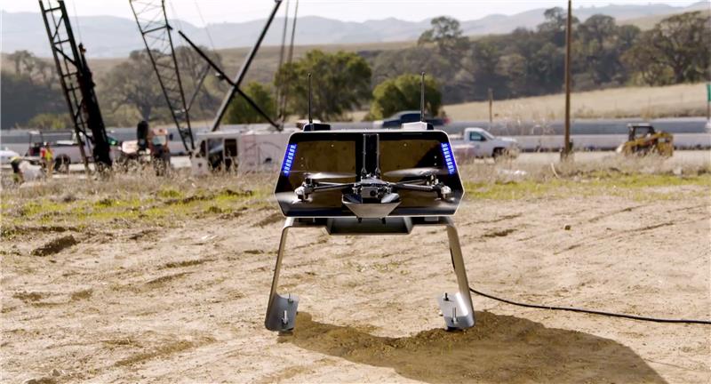
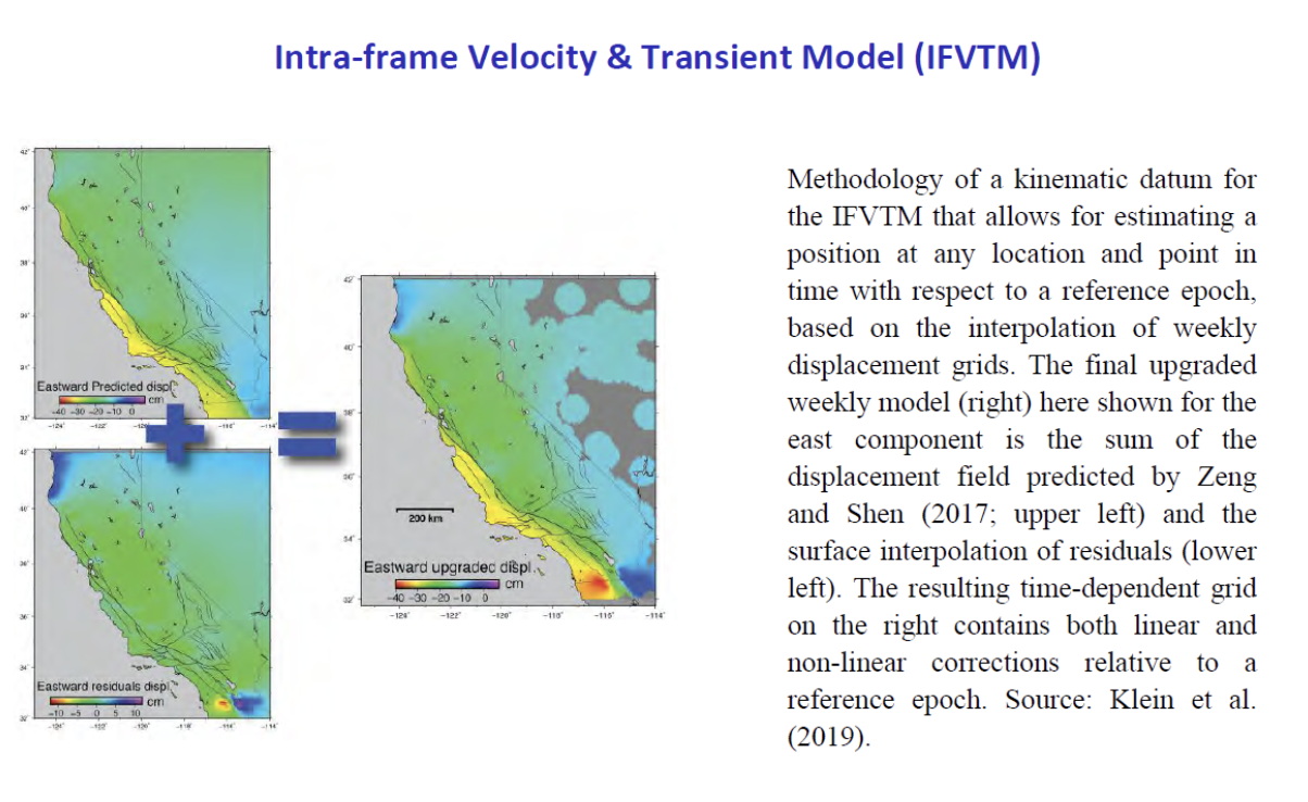
    Prior to the advent of tilt compensation for surveying and construction GNSS rovers, there were incremental approaches to tilt, with limited success. However, five years ago, “no-calibration tilt compensation” was first incorporated as a standard option for rovers. Some users remain skeptical or exercise the same caution as they did when such innovations as EDMs were first introduced. Nevertheless, the adoption of tilt compensation — for appropriate tasks — has spread rapidly. How did we get to this point?

    For centuries, plumb bobs and bubbles were the only viable options to level an instrument or pole about a point. Early references to spirit levels appeared in the 15th century; however, siphon style water levels may have been in use in ancient Greece, China, and elsewhere for much longer. In more recent centuries, various types of level vials became a standard feature for surveying transits, theodolites and levels. Vials with a slight upward curve position a bubble between defined center marks when level.

    Circular, convex glass bubbles appeared for industrial applications in the 19th century and were soon incorporated into surveying instruments and survey poles. In recent decades, electronic bubbles, or “e-bubbles” emerged, using microelectromechanical (MEMS) tilt sensors along with various methods to apply an orientation to compute the position of the pole tip relative to the phase center of the GNSS antenna. This is in contrast to relying on a bubble alone to orient the phase center directly above the pole tip.

    There are both pitfalls and potential productivity losses if the pole has to be leveled solely with a bubble for each measurement; we’ll examine these later. If freed from the bubble — as electronic bubbles, tilt sensors, and various methods for orientation enable — how much productivity gain can be realized? For which tasks do the users find tilt compensation most useful? For which do they not? We talked with manufacturers, dealers and field users to find out.

    Early adopters

    Tilt for safer surveying. (Image: Lee Landman)
    Tilt for safer surveying. (Image: Lee Landman)

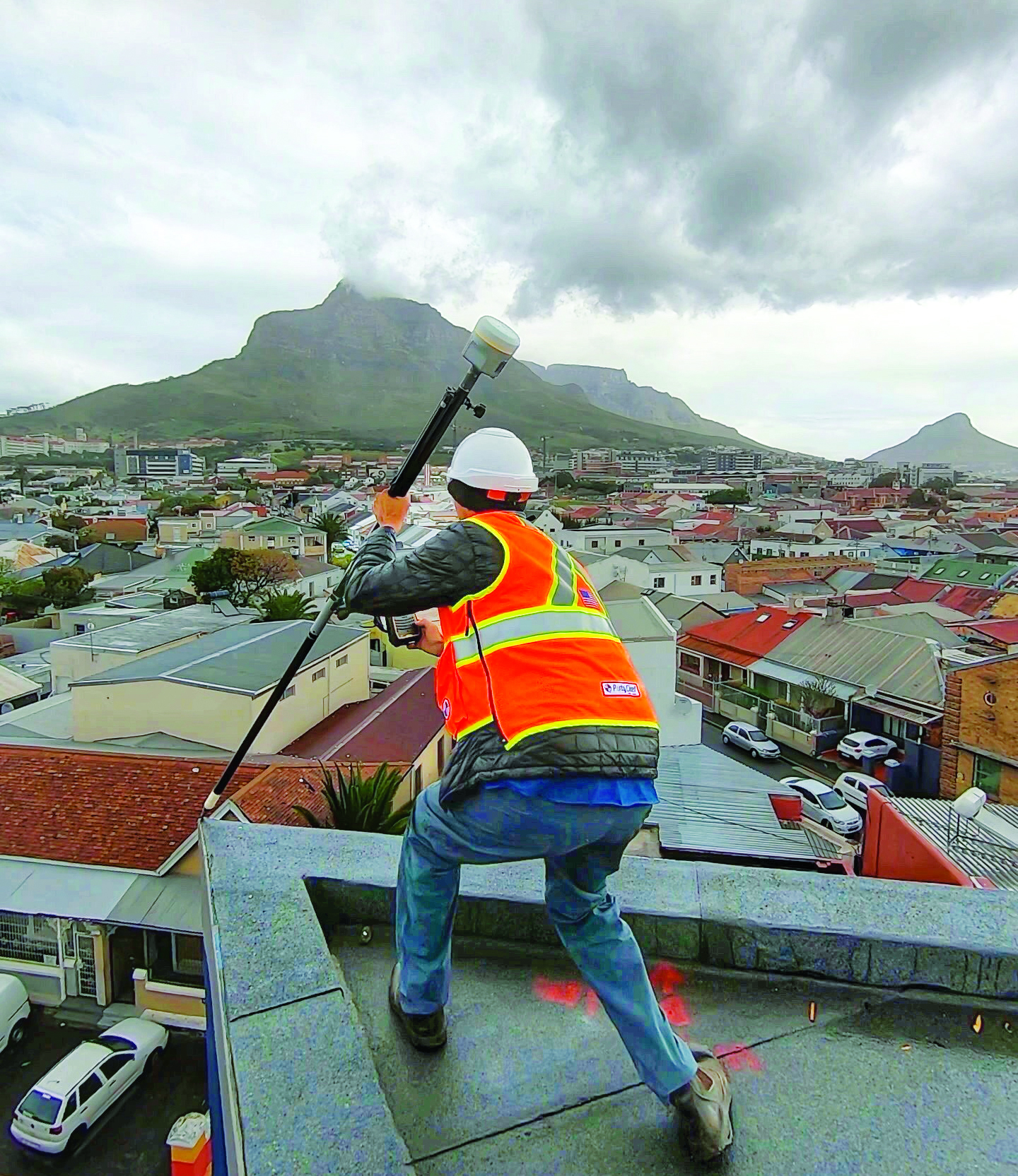
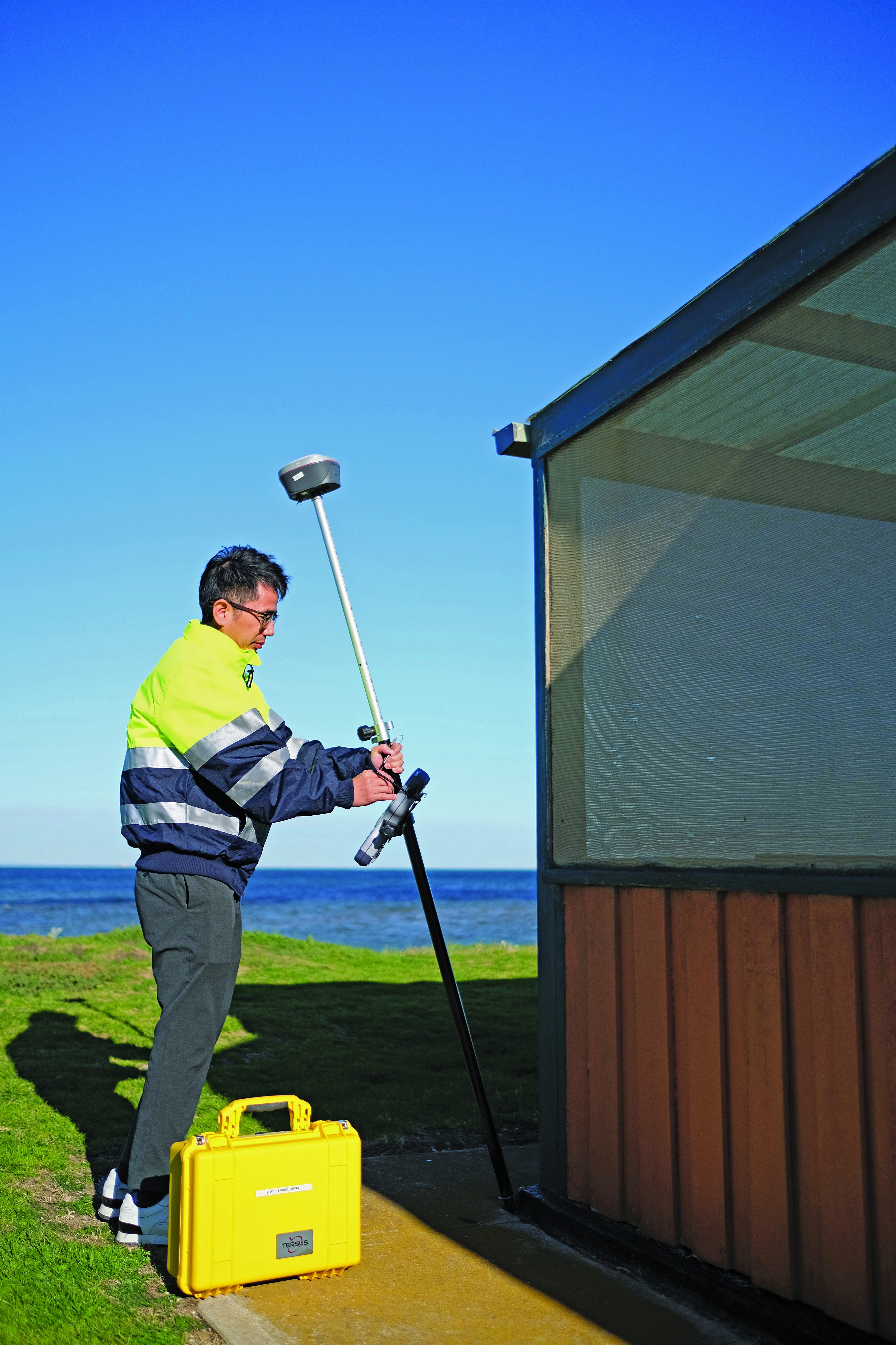
    Lee Landman owns a firm in the Cape Town area of South Africa that provides construction layout, civil engineering layout and related topographic mapping services. Landman obtained a Trimble R12i GNSS rover, with no-calibration tilt, shortly after its release in 2020.

    “Tilt is my go-to tool for almost all tasks now, except layout that needs better than 15 mm to 20 mm tolerance,” Landman said. “For topographic mapping, I will get everything possible with tilt, and then use a total station to get the points I can’t with the rover.”

    Landman reports productivity gains of 30% to 50% on certain jobs. His crews will try to leverage a tilt rover for as much of a job as they can, provided it meets precision needs. For checking work, such as grade checking or layout verification, they will try to use tilt for everything first. Then in any areas that look suspect, they will set up a total station to confirm. He said this saves a lot of time up front.

    After several years of use, Landman said there are specific tasks where they will not use tilt, and we find this echoed by other users interviewed (and from my own tests). For instance, construction layout of such structures as walls and columns where a consistent 5 mm to 10 mm tolerance is required. He said the same applies for tasks where precise elevation is key, such as on road curbs and final road levels. However, he noted: “That’s a GNSS precision thing, not a tilt issue.”

    Landman provides other caveats,“I am nervous using tilt on long rods or when you constantly change rod height, as the results of using a wrong rod height would be disastrous, and the deflection on long rods could also degrade the results.”

    Summarizing the overall impact on his operations, Landman explained, “We have become more competitive. Not by sharpening our price, but by the fact that using tilt is less fatiguing and faster to do layout and data collection. That gives us an edge over firms that are not using it.” He provided the example of a foundation layout that needed 300-400 points laid out and chalked in an hour or two so that the excavators that were standing by could start digging as soon as possible. “It normally takes two to three moves of the pole and bubble checks to get a point on position without tilt,” Landman said. “Now, when you are doing 300 points, that is 600-900 times that I don’t have to look at the bubble and adjust the rod. The amount of energy and fatigue that saves is just outstanding. No sore lat muscles and eye fatigue.”

    In the southwest of England, where Benchmark Surveys operates, fields and roadways are often lined with thick brambles, making if difficult to shoot features underneath them, such as utilities. James Richards of Benchmark says tilt has revolutionized the way they survey, enabling shots in places where even a total station (where the rod needs to be plumb) cannot take them. (Image: Benchmark Surveys)
    In the southwest of England, where Benchmark Surveys operates, fields and roadways are often lined with thick brambles, making if difficult to shoot features underneath them, such as utilities. James Richards of Benchmark says tilt has revolutionized the way they survey, enabling shots in places where even a total station (where the rod needs to be plumb) cannot take them. (Image: Benchmark Surveys)

    Then there are shots that you cannot get with a bubble plumbed pole, Landman said. For instance, in checking rebar layouts prior to construction, as well as marking out on or below the steel rebar cages for plumbing points, voids and slab penetrations.

    “Previously we could not easily do this, as you cannot get the pole plumb for total station shots or GNSS to place or check a point,” Landman said. “You just have to check positions on the steel for a column or wall to see if it has enough concrete cover or is in the right position prior to pouring concrete.”

    James Richards is the survey manager for Benchmark Surveys, a family-owned and operated firm in the southwest of the UK that has steadily grown its portfolio of services. In part, this growth has resulted from their willingness to embrace new and emerging technologies. This included adding tilt compensated R12i rovers to their instrument inventory shortly after they became commercially available.

    “We use tilt on every surveying task where we can use GNSS,” Richards said. “Tilt has enabled us to complete numerous jobs where we would have otherwise only been able to use a total station.” Apart from control, there are not many tasks for which Richards would not recommend using tilt, “It has helped improve our surveys. We can capture data quicker and easier than before and with greater accuracy.” Examples of daily challenges his crews face include getting shots in and around ditches, field boundaries, and boundary fences in foliage, and walls with foliage overhang. These are now easily captured using tilt.

    “Tilt has had an enormous impact on our business. We complete work to a higher standard, capturing data quicker and easier,” said Richards. “It helps us capture data that was not possible without offsets. We’ve seen a rise in profitability since using tilt. Surveyors seem to be happier with day-to-day work, knowing that they can capture the data required to meet our high standards, and clients are also happier when receiving more data than expected from surveys.”

    Stages of adoption

    CHC Navigation is a GNSS developer and manufacturer that has sold hundreds of thousands of units over the past 15 years. They were quick to develop and implement tilt compensation technology, which has now become standard on all of their current models.

    Rachel Wang, product manager of CHC Navigation’s Surveying and Engineering division explained the four stages they undertook in developing tilt.

    “In the first stage,” said Wang, “users had to rely on the survey pole’s bubble to maintain a centered state, which had significant limitations in terms of measurement accuracy and accessibility.”

    In addition to any GNSS error, there could be additional error due to a poorly calibrated bubble, a pole that is not straight, misalignments with each joint of telescoping rods, and user error in trying to keep the bubble lined up while simultaneously operating the field collector (if not using a bipod). Often it seemed that a surveyor would need extra hands and an extra set of eyes.

    “The second stage introduced the first generation of tilt compensation using an electronic compass,” said Wang. “Although this technology enabled the first tilt measurements, it was hampered by problems such as low accuracy, tedious calibration, poor reliability, and susceptibility to interference from electrical currents or magnetic fields.”

    Common applications for tilt features include getting shots up against structures and improving sky view. For example, for this bridge column with sky partially obstructed by the bridge deck. (Image: CHCNAV)
    Common applications for tilt features include getting shots up against structures and improving sky view. For example, for this bridge column with sky partially obstructed by the bridge deck. (Image: CHCNAV)

    Such magnetic oriented tilt compensation had been implemented on rovers several years prior to no-calibration methods, by manufacturers that included Javad, Trimble, Topcon, and others. The calibration step often involved rotating the rover vertically in eight or more horizontal positions. This was cumbersome, and the orientation quality changed over time, mostly unbeknownst to the user. It was no surprise that “mag tilt” never really caught on, and unfortunately it made some users wary of tilt in general, even when no-calibration solutions came along.

    “The third step was the development of the second generation of tilt compensation, using hybrid positioning based on GNSS + IMU,” Wang said. “This technology was less affected by magnetic interference, but still required initialization of the IMU by shaking the survey pole.” I had tried several models from manufacturers of early “minimal calibration tilt” enabled rovers. For each, a certain amount of movement had to be induced on the pole, by walking around a bit, swinging the pole back and forth, or in a circular sweep. It often did not take more than a minute or so, and then normal moving around on the site would usually keep it calibrated. This was a tremendous step up compared to the old “mag tilt.”

    “More recently, we are proud to announce the fourth step in our tilt measurement technology integrated into our new i93 GNSS RTK rover,” Wang said. “Our Auto-IMU technology further simplifies the IMU initialization process by observing acceleration at some point between startup and RTK operation. This replaces the previous repeated shaking of the survey pole for initialization. In fact, users can initialize the IMU while walking or moving normally. In addition, once initialized, the IMU feature is not easily lost even if the pole is carried on the shoulder, held horizontally, or even upside down.”

    Wang said that all current CHC survey rovers are equipped with their newest tilt compensation technology. Since the international launch of their first CHCNAV GNSS RTK with IMU, the i90 GNSS in 2019, they have continued to incorporate this feature into all subsequent GNSS rovers. “Based on feedback from users, we know how valuable this feature is,” said Wang. “That is why we have made tilt compensation a standard feature on our current i73, i83, i90 and i93 models.”

    Uptake

    Greg Maier of the City of Kelowna, Canada, was an early adopter of tilt. He found it invaluable to access hard to reach features, such as this inlet under a car, and for safer surveying along the edges of roadways. (Image: Greg Maier)
    Greg Maier of the City of Kelowna, Canada, was an early adopter of tilt. He found it invaluable to access hard to reach features, such as this inlet under a car, and for safer surveying along the edges of roadways. (Image: Greg Maier)

    For the past year, I’ve been talking to other GNSS manufacturers, their dealers, and customers, together with monitoring the subject in surveying and construction groups and forums online. Manufacturers have reported overwhelmingly positive feedback from dealers and customers about the tilt function. Typical feedback focuses on convenience and time savings of not having to level the pole manually.

    “Based on our research, we have found this feature to be extremely useful for surveying and staking out on construction sites,” Wang said. “It has increased speed and efficiency by up to 30%.” I have heard similar statistics from each of the manufacturers contacted, as well as their dealers, and most of their customers that have used tilt.

    There are common threads to much of the feedback from various sources: the tilt function is now an indispensable tool for many surveying applications.

    As Wang noted, “While some users still prefer to use the traditional bubble to plumb the pole, we have seen a clear trend toward adoption of the tilt function in the field. The benefits of tilt, such as faster and easier surveying, are becoming more apparent to our users. As we continue to improve the accuracy of our tilt-compensation, we expect that more and more users will choose this convenient feature over other traditional GNSS rovers in the future.”

    Another common observation (no pun intended): even if the pole-tilt feature offers significant convenience and time-saving benefits, it may not be the best option for tasks that require very high accuracy, such as surveying control points. For such tasks, manufacturers, dealers, and users recommend using the traditional bubble on a pole with a bi-pod mount for more accurate measurement.

    As something completely new, the uptake across the surveying profession and for construction took time to grow. “It took quite a while to catch on here,” said Keith

    Belsham, branch manager for Spatial Technologies, a measurement solutions dealer in the Vancouver region of British Columbia Canada. They specialize in solutions from Leica Geosystems and were an early provider of the Leica GS18 T, widely recognized as the first GNSS rover with no-calibration tilt.

    “My perception is that in the United States and some other countries, there are more companies trying to stay at the top of technology,” Belsham said. “However, in our region surveyors are very cautious and need to do a lot of checks and look to see how others respond before they consider it. It was that way with other new technologies; I have memories of numerous total station demonstrations, when prism-less EDM’s were first coming out, where surveyors would pull out a tape measure to check whether the instrument was giving the correct distance.”

    About three years after the introduction of no-calibration tilt is when Belsham said it really took off in his region, and it is now quite popular. He gave an example of a customer buying a Leica GS16 (no tilt), saying that they did not see a need for tilt, considering the extra expense. They then upgraded a week later once they were in the field and recognized many instances where the tilt would have saved them time.

    Rather than go the OEM route, Tersus GNSS developed its own GNSS board, positioning engines, and IMU tilt integration. (Image: Tersus GNSS)
    Rather than go the OEM route, Tersus GNSS developed its own GNSS board, positioning engines, and IMU tilt integration. (Image: Tersus GNSS)

    A Spatial Technologies customer that has found tilt useful for numerous applications is Lucas Geomatics, a surveying firm based in Surrey B.C. “When I set up GNSS units for construction companies, tilt is great as they don’t have to be super accurate,” said Peter Smith. “I mean, here’s a machine with a bucket that’s 3 f wide, and the bucket is about an inch thick. The grade checked does not have to be super accurate for the machine to hit it, because end users in construction companies do not have to do precise surveying. They’re great guys who dig trenches and tilt gives them more than enough precision for their needs.”

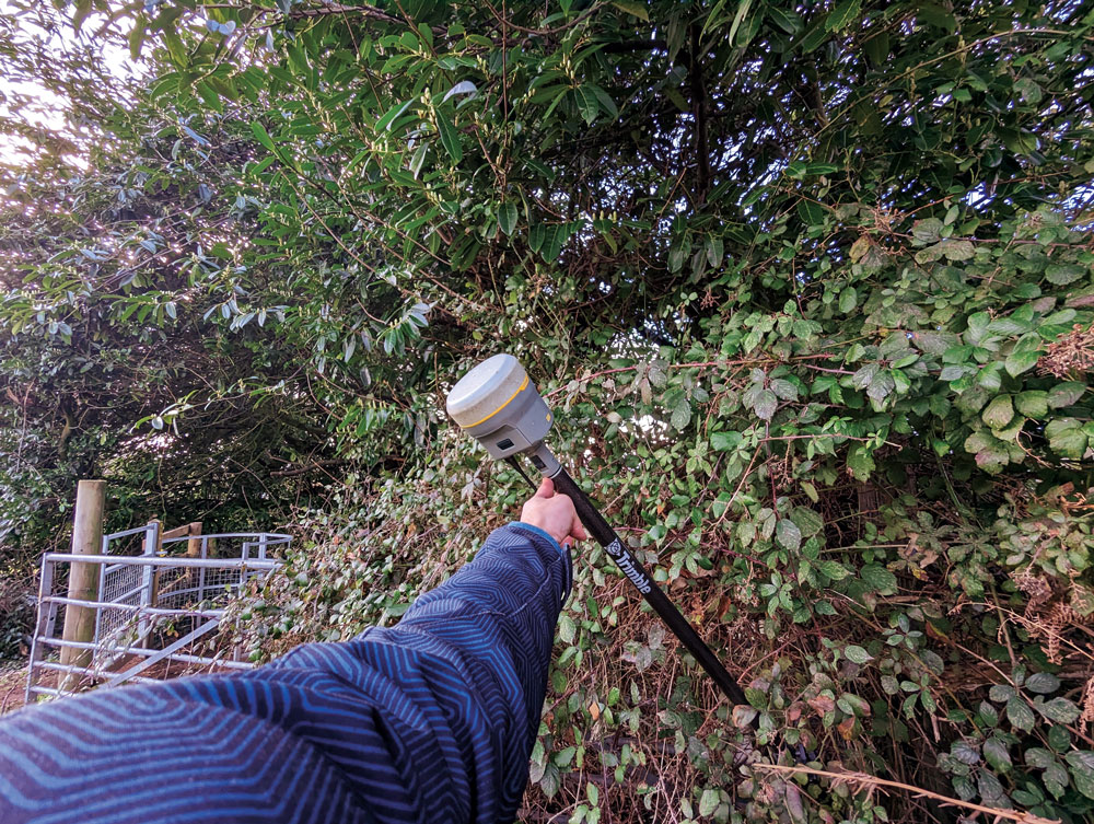
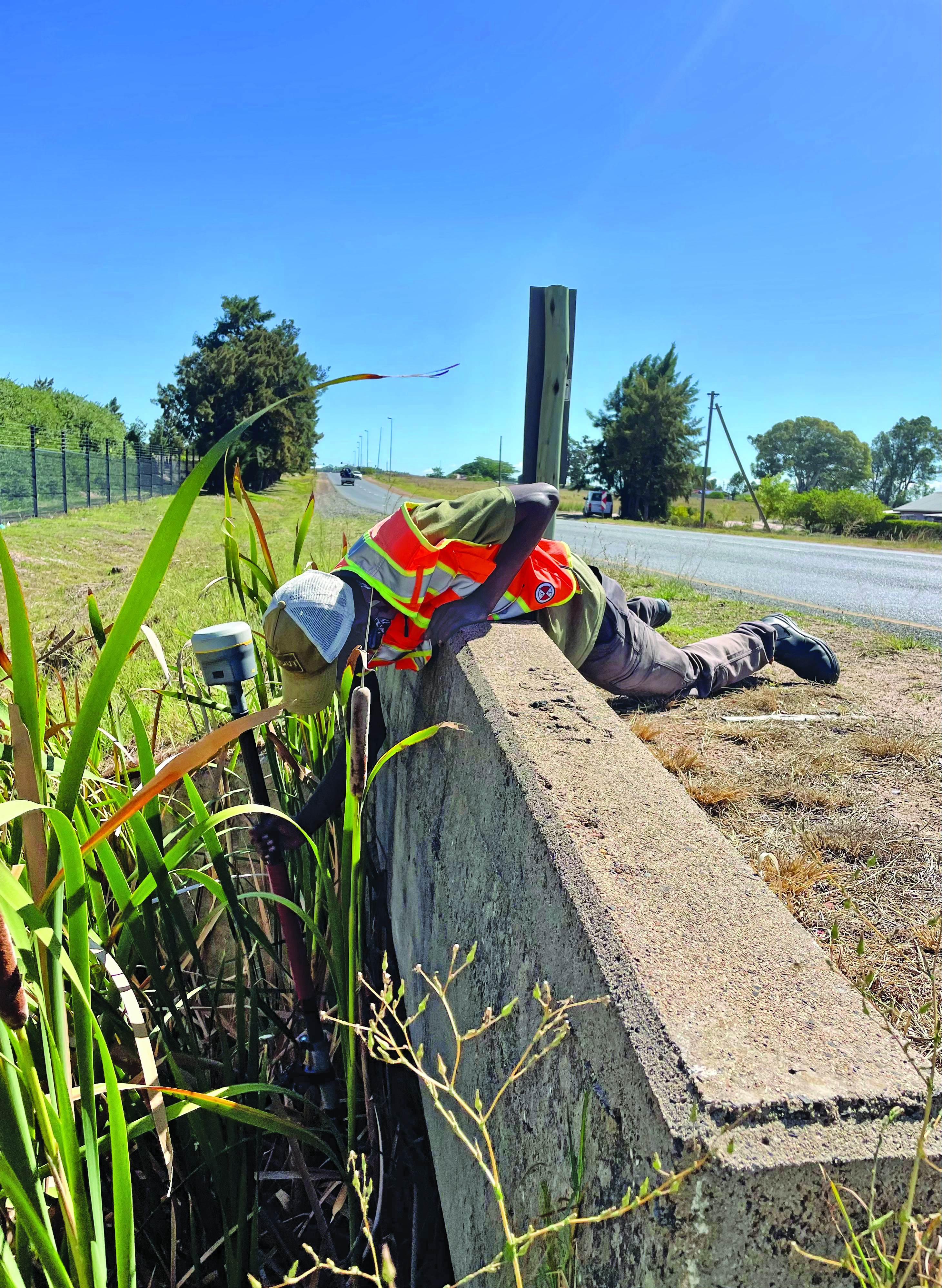
    Among the many uses Smith has found for tilt, he has also adapted it in a very creative way to deal with areas of deep foliage. A common approach to working in thick foliage is to raise the GNSS rover up on a tall or extended pole; this can increase the number of satellites viewed and reduce multipath. However, working with a bubble low enough on the pole to see makes it quite difficult to keep the rover at the top sufficiently still and plumbed over the tip. I remember some clever (albeit questionable) solutions folks cobbled together to help plumb very tall poles, such as a small live video camera pointing down over a bubble near the top of the pole to view on a phone. Smith said that tilt solved this problem, and he uses various tall rods, including one that extends to as much as 12 m. He chose a non-conducting pole, such as those used by utility companies for high foliage.

    He does prefer to use the rover on a bipod, though, and bubble for control and points requiring very high precision. He sets the data collector software to log positions at 5 Hz or 10 Hz (standard in most systems) and has the software average multiple positions over the course of a minute or more.

    Smith said that tilt has made a lot of difference in their surveys, especially where they want a lot of productivity, but do not need very high precision. Part of why he is impressed with the GS18 T is that they had upgraded from an older system, that only used two constellations, to full constellation support on their new rover.

    Stability through motion

    It sounds counter to one of the key principles for surveying measurement: the instrument and pole must be kept very still. However, in other data collection technologies, including aerial mapping and mobile mapping, leveraging predictable motion, acceleration, and trajectory caught on decades ago. There are numerous integrated GNSS + IMU solutions from, for instance, Applanix and NovAtel, that are the key positioning components for kinematic mapping systems. Such integrated sensor solutions are also in broad use now for UAV real-time and post-processing workflows.

    One challenge for integration into survey rovers, was miniaturization. Additionally, such solutions needed a wealth of satellites and signals to be usable at tilted angles. The Galileo and BeiDou constellations reached full complement at about the same time as no-calibration tilt was introduced. Some manufacturers even integrated new antenna designs to better utilize satellites at tilted angles, for example in the Leica GS18 T.

    The electronic bubble aspect of such solutions was in some ways the easiest to achieve. Depending on the quality of components, multiple tilt sensors can measure the angle of tilt at precisions matching, or even bettering that of typical pole bubbles. Plus, they are built into the rover boards with a direct relationship to the axis and phase center, whereas the bubble is external, down on the pole.

    Integrated IMUs, with as many as nine axes, are highly sensitive, as are accelerometers (if an integration utilizes those). Skeptics always point out that IMUs are subject to drifting over time. However, the observed high-rate GNSS positions and motion sensors are continuously updating the calibration of the IMU. It is true of no-calibration tilt systems that if you hold the pole still too long, it will lose its calibration. Or if you move it too fast. Though on every tilt rover I’ve tried, I moved it around vigorously and spun it (more than would happen in normal operations) and it still kept its calibration. There can also be instances of environments with excessive multipath hazards — such as heavily wooded areas, urban canyons, or congested construction sites — where users often find it best to turn off the tilt for certain shots.

    Industry penetration

    Tilt for shooting inverts. (Image: Lee Landman)
    Tilt for shooting inverts. (Image: Lee Landman)

    While manufacturers have approached the GNSS/IMU solution in varied ways, the fundamentals are the same. Once some of the major vendors developed and integrated tilt, they began offering this feature for OEM customers, and in recent years we see tilt on many other brands worldwide. There are relatively new players in the market that took a different approach, developing not only their own GNSS boards and positioning engines, but IMU solutions as well.

    Tersus GNSS has rapidly gained a presence in various global markets, though relatively new in North America. While starting as an OEM, the company pivoted to developing its own boards in 2015, and GNSS + IMU integrations more recently. It recently published a paper about what they call its “Extreme RTK Solution” that has a section with data from their own tests for both plumbed and tilted observations.

    I did some quick tests with a Tersus Oscar Ultimate, at various angles of tilt, and in mixed environments. The results aligned closely with those in the paper, as did tests with other tilt rovers. I have had the opportunity to try rovers of several different brands, to check precision at various tilt angles against points established with static observations (to see how much the tilt added to the total error). While these were not comprehensive tests, I did compare notes with surveyors who did their own tests, and we’ve all been finding out the practical limits of tilt. Perhaps part of why tilt took a while to catch on was that surveyors needed some time with these units in real-world environments, to get a feel for sweet spots for tilt for different tasks that have specified error budgets.

    To get an idea of potential productivity gains, I did a small topographic survey of an area I had previously surveyed with a conventional rover, total station, and scanner. The total station and tilt-less GNSS took about the same amount of time — but with tilt it took about half the time. Many variables can and do come into play, but the figure I keep hearing of up to 30% efficiency gain for many applications seems realistic. Certainly, for asset and resource mapping, tilt could easily fit the looser precision requirements.

    As for degradation at various angles of tilt, checks against static points (beyond standard GNSS error) showed negligible differences under 5°, 1 cm up to 15°, 2 cm or more around 45°, and 3 cm or more at 60°. This was just a cursory look, and indeed any surveyors that use tilt should do their own testing. I did notice in the data that when doing simple topo shots, just moving around the site, the pole did not often exceed 5°. Therefore, moving around quickly and efficiently for topo, not having to look at the bubble, improves productivity without significantly compromising quality.
    Layout, as surveyors and construction folks who use tilt say, can be quite a snap compared to the old “plumb-shoot, move-plumb-shoot, move-again-plumb-shoot, etc.,” process. You simply move the tip of the pole around until you are on the point.

    Enabling further sensor integration

    tilt compensation has now extended to non-GNSS tech, for instance Leica Geosystems AP20 prism poles (used with robotic total stations). (Image: Gavin Schrock)
    Tilt compensation has now extended to non-GNSS tech, for instance Leica Geosystems AP20 prism poles (used with robotic total stations). (Image: Gavin Schrock)

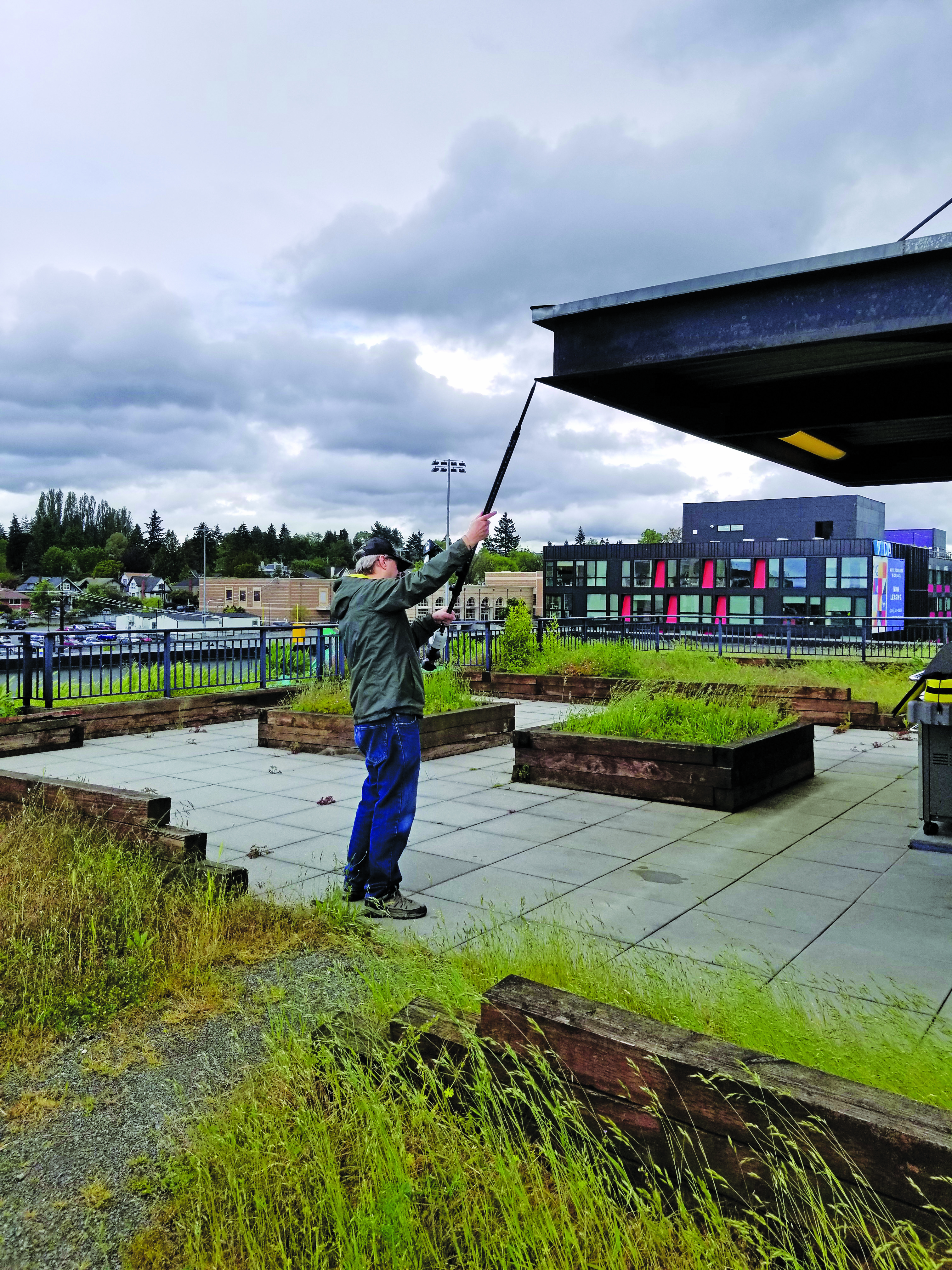
    No-calibration tilt, and multi-constellation GNSS, have enabled further developments that may not have been practical otherwise. Leica has since added an image point extraction feature to its GS18I. This marries the tilt and a camera with a clear path to processing the images in the data collector software. With tilt running, and at ranges under 6 meters, you can roughly aim the camera side of the rover toward say, features under an overhang, that you would not otherwise be able to shoot with a GNSS alone. You walk past the features as the camera takes a series of images. Then, in the software, you identify the points in multiple images and photogrammetrically it gives the offset. You can also process the image series into point clouds. There were several attempts at this sort of solution in the past by various brands. However, without tilt it was too cumbersome as you would need to stop and plum for each image in the series. As one user told me, the new image point features are “like having a UAV on a pole.”

    Tersus GNSS has taken a slightly different approach to their image point solution. You pick the point you desire in the camera view on the data collector, and then move along as the software automatically identifies the same point in subsequent frames, until it has enough matches from multiple angles to calculate the offset. CHC Navigation has just announced its own image point feature, with a two-camera integration in the i93 Visual GNSS RTK rover.

    Pole tilt also has been integrated into non-GNSS solutions. For instance, the recent release of a prism-pole tilt solution by Leica, the AP20. A constant stream of positions of the prism, from the total station, takes the place of GNSS in this application. They’ve also included a rather clever automated pole-height feature.

    What could be next? Perhaps small solid state lidars on rovers, or combined lidar/camera solutions such as on an iPhone/iPad, or a tiny SLAM scanner (that could also aid in position stabilization)? Not to mention what might be coming in the not-too-distant future in the realm of quantum sensing.

    In considering all feedback about no-calibration tilt, it seems it is very much here and here to stay. There are many who love it and try to use it for everything (perhaps, in some cases, too many tasks). For others, it is conditional love: use where appropriate. While others still hate it immediately, perhaps on principle, though I find those folks typically have never tried it. Legacy tools and methods provide comfort and known levels of risk. New features such as tilt, provided some time is spent gauging its performance and appropriateness for various tasks, can deliver productivity gains that should prompt reevaluation of some long-held assumptions.

  • Hexagon│NovAtel receivers track Xona PULSAR LEO signal generated by Spirent simulator

    Hexagon│NovAtel receivers track Xona PULSAR LEO signal generated by Spirent simulator


    Image: Hexagon │ NovAtel
    Image: Hexagon │ NovAtel

    Hexagon│NovAtel’s OEM7 GNSS receivers have successfully tracked Xona Space Systems PULSAR signals generated by a simulator from Spirent Communications. This test proved NovAtel GNSS receivers can track a Spirent simulated L-band signal identical to the PULSAR signal broadcast by Xona’s low-Earth orbit (LEO) satellites.

    The Xona LEO signals will complement GNSS, improving resiliency, security, and precision for positioning, navigation and timing (PNT).

    “Using Spirent’s simulated PULSAR signal, we have successfully tested our receiver’s capability to track the L-band signal planned to be broadcast from Xona’s LEO satellites,” Sandy Kennedy, VP of innovation at Hexagon’s Autonomy and Positioning division, said. “The OEM7 is a powerful platform, designed for both resiliency and flexibility; it is exciting to test our forethought by trialing this new signal type.”

    Join Hexagon│NovAtel on Thursday, June 15, at the ION Joint Navigation Conference (JNC) where it will co-present “Testing of LEO PNT for Resilience in GNSS Contested Environments.

  • Septentrio and Xona Space Systems collaborate on GNSS receiver

    Septentrio and Xona Space Systems collaborate on GNSS receiver

    Image: Septentrio
    Image: Septentrio

    Septentrio and Xona Space Systems have collaborated to develop an experimental receiver compatible with Xona multi-frequency PULSAR signals.

    The multi-frequency receiver will be one of the first to decode all PULSAR signals alongside standard GNSS signals such as GPS, Galileo, GLONASS and BeiDou.

    Septentrio will be showcasing this receiver at the ION Joint Navigation Conference, June 12-15, 2023, in San Diego, California.

    “As Xona PULSAR signals become available, a Septentrio receiver will offer users an opportunity to be the first to experiment with PULSAR and GNSS in many different scenarios,” Bryan Chan, VP of business development and strategy, Xona Space Systems, said.

  • Skydio gets BVLOS approval for UAV operations in Japan

    Skydio gets BVLOS approval for UAV operations in Japan

    Image: Screenshot of Skydio product video
    Image: Screenshot of Skydio product video

    The Japan Civil Aviation Bureau (JCAB) has granted Skydio nationwide approval to remotely fly UAVs beyond visual line of sight (BVLOS). The approval enables streamlined BVLOS operations using Skydio Dock and Remote Ops.

    Skydio’s artificial intelligence and autonomous technology enables UAVs to safely fly missions near structures in a way that would be difficult or impossible with manually-operated UAVs — even when operated remotely without a pilot on-site.

    Under the JCAB approval, there is no requirement to use additional crew members, such as visual observers, or technology to detect crewed aircraft — eliminating some of the challenges faced by UAV operators. The BVLOS approval applies across Japan.

    Notification of the flight area is required prior to takeoff using JCAB’s web portal. Operators can now remotely inspect critical infrastructure — buildings, roads, power plants and the scenes of natural disasters — safely and quickly without placing people at risk.

  • Trimble releases laser scanning system

    Trimble releases laser scanning system


    Image: Trimble
    Image: Trimble

    Trimble has released the X9 3D laser scanning system — a versatile reality capture solution suitable for surveying, construction and engineering users. The X9 is designed to enhance performance in more environments while leveraging Trimble’s X-Drive technology for automatic instrument calibration, survey-grade self-leveling and laser pointer for georeferencing.

    The X9 expands on Trimble’s X7, delivering longer range, higher accuracy, shorter scan times and sensitivity, improving scan results. Advanced processing and a high-performance laser increase the sensitivity of all scans, enabling the X9 to capture difficult dark or reflective surfaces. A new center unit design also improves signal transmission for better scan quality.

    The X9 provides accurate and dependable data, enabling confident decision making both in the field and in the office through in-field registration with Trimble Perspective and FieldLink software by minimizing the need for target deployment. The auto-calibration eliminates the need for annual calibration.

    In addition, the X9 includes survey-grade self-leveling with the industry’s widest compensation range for fast, easy setup.

    The X9 data can be delivered directly from the Perspective or FieldLink software to Trimble’s office software — including the Realworks 3D scanning software — business center office software, SketchUp and Tekla, or exported to industry-standard formats to produce application-specific deliverables.

  • Autonomous trucks begin testing on Japanese expressway

    Autonomous trucks begin testing on Japanese expressway

    Image: TuSimple Holdings
    Image: TuSimple Holdings

    TuSimple Holdings, a global autonomous driving technology company, has started Level 4 autonomous test runs on the freight corridor that connects the major cities of Tokyo, Nagoya and Osaka.

    In 2021, TuSimple Japan, a subsidiary of TuSimple, completed a series of safety validation and testing work of its autonomous driving system with a truck provided by a Japanese OEM. In January, TuSimple Japan commenced regular testing on the Tomei Expressway.

    It has been reported that the Japanese government is planning to launch a self-driving lane on some sections of the new Tomei Expressway by 2024 and will allow commercial operation of SAE Level 4 fully autonomous trucks in 2026.

    TuSimple is developing a commercial-ready, fully autonomous (SAE Level 4) driving solution for long-haul, heavy-duty trucks. As of March 2023, TuSimple trucks have recorded more than 10 million cumulative miles through testing, research, and freight delivery.

  • Tallysman, u-blox partner on GNSS antennas and receivers

    Tallysman, u-blox partner on GNSS antennas and receivers


    Image: Tallysman Wireless
    Image: Tallysman Wireless

    Tallysman Wireless and u-blox have partnered to develop PointPerfect precise point positioning real-time kinematic augmented smart antennas.

    The ZED-F9R high precision GNSS and the NEO-D9S L-band receivers from u-blox have been integrated with Tallysman’s technology. The product integration will provide accuracy and precision.

    The multi-band (L1/L2 or L1/L5) architecture removes ionospheric errors, and the multi-stage enhanced XF filtering improves noise immunity while relying on the dual-feed Tallysman Accutenna element to mitigate multi-path signal interference rejection. Some versions of the new smart antenna solutions include an inertial measurement unit (dead reckoning) and an integrated L-band corrections receiver to ensure operation beyond terrestrial network reach.

    The PointPerfect GNSS augmentation service is now available in North America, Europe and parts of Asia Pacific.

  • GNSS at the front end and back end  of Intelligent Transportation

    GNSS at the front end and back end of Intelligent Transportation

    Image: Hexagon | NovAtel
    Image: Hexagon | NovAtel

    It has been a wild decade, with so many players in the autonomous vehicle (AV) market, all striving for a leg up. Until the dominant design of present AV stacks emerged, there was no small amount of experimentation and less-than-successful alternate approaches. For instance, there was one big-name player that initially sought to create an AV solution without GNSS. Reality set in, and they soon embraced GNSS as an essential component.

    Gordon Heidinger, segment manager, automotive and safety critical systems at Hexagon’s Autonomy and Positioning division, has had a front-row seat from which to observe, and contribute to the evolution of AV.

    “I’ve been in the automotive industry for 20 years, all the way from OEMs like Chrysler to tier ones like Harman,” Heidinger said. “I’ve worked on the engineering side, on the project management side, and have now joined Hexagon | NovAtel to help further their involvement in the automotive industry. NovAtel was there for aviation 20 years ago, helping develop systems for planes to take off and land autonomously — we have a deep bench when it comes to applying such expertise for vehicular autonomy.”

    NovAtel has long provided GNSS and IMU products and solutions, as well as real-time positioning services. Each are key elements of AV sensor stacks and overall autonomy solutions. Parent company Hexagon has multiple divisions contributing to intelligent transportation — on both the front end and back end.

    The Front End

    AV systems require highly reliable and smart sensor stacks that typically include cameras, radar, lidar and sonic sensors; these provide the relative positioning for advanced driver assistance systems (ADAS), which are becoming commonplace for newer vehicles. There are also implementations that include GNSS/IMU for navigation and lane keeping.

    “Lane keeping is possible to a limited degree with combinations of the other sensors; however, you need GNSS to let you know where you truly are for autonomous driving,” Heidinger said. “Are you on the right freeway lane in Ottawa, or is this an exit ramp? This was a big problem with today’s simple single frequency solution; a car can assume highway speeds on an exit ramp, not realizing it was an exit ramp.”

    Only with the absolute precise positioning that GNSS provides, and a high-definition map, level 4 autonomy — and potentially level 5 someday — could be achieved. With current sensor stacks, when the car is moving, it can reliably detect the other cars moving in its vicinity. Furthermore, vehicle-to-vehicle (V2V) solutions are being developed and tested, which enable a vehicle to share data about where it is going, its speed and acceleration, and its current location. We may remain far from full autonomy until such solutions are broadly deployed, however we will see some of the vehicle-to-everything (V2X) solutions sooner than later.

    Various developers and departments of transportation around the world are testing short range V2X communication systems.
    “We would need real-time construction zone updates,” Heidinger said. “It would be tough to do lane keeping if a construction site closes or diverts lanes during the course of a day. Or if cameras detect crashes, or blocked lanes, this will need to be broadcast immediately and continuously in real-time.”

    A representative example of a production high precision positioning system was demonstrated at the recent Consumer Electronics Show 2023 (CES 2023). ZF Friedrichshafen AG (ZF) has developed ProConnect — a dedicated short-range communication (DSRC) solution that enables positioning and communication for use in applications with roadside infrastructure, such as traffic lights. It can be scaled to include other over-the-air alerts that could include first responder vehicle proximity and construction site status. At CES, the GNSS positioning was demonstrated with an autonomous vehicle platform from Hexagon.

    “The precise map and the real-time updates from V2V and V2X systems all need precise absolute positions to relate objects to each other,” Heidinger stated. The question then becomes “…how reliable and trustworthy is that solution”?

    There are international automotive-grade requirements such as the ISO 26262 standard for electrical/electronic systems, and automotive safety integrity levels. For instance, ASIL-B(D), and cybersecurity standard ISO/SAE 21434. The latter provides protection against external access without authorization.

    “The level of reliability required is extremely high,” Heidinger said. “After all, these are human lives, in metal boxes hurtling along at highways speeds. There are ASIL standards that call for a probability of 10-8, or 1 in 100 million, in an hour that the system is wrong. These levels of reliability need to apply to electronic components, communications, and the availability of the GNSS positioning solution to really automate any type of vehicles. You’ll encounter similar AV standard references to five-nines, or 99.999%.”

    Positioning Services

    Heidinger explained that for most aspects of autonomy, GNSS can be “good enough”, even just to a foot. However, uncorrected, GNSS can never meet even those needs — achieving an accuracy of a few meters at best. Then there is the matter of reliability. Augmentations like real-time kinematics (RTK) and precise point positioning (PPP) apply broadcast “correctors” that can yield centimeter positions. RTK is not practical for broad areas or highway and road networks as it requires dense infrastructure and two-way communication with the vehicle, which can introduce security challenges.

    Solutions for autonomy are typically PPP. While there are many applications of PPP that use clock, orbit and ionospheric model data broadcast from geostationary L-band satellites, for applications such as surveying, mapping, maritime and agriculture, this would not meet the reliability requirements for AV. The Achilles heel of broadcast PPP is that the satellites are usually limited in number and positioned over the equator; the vehicle can often lose sight of these. Instead, PPP services, such as that provided by NovAtel and others, are tapped by vehicles via mobile internet connections; this means cellular networks. While cellular services can often meet reliability goals, there are still vast areas of highways where availability is sparse.

    The other challenge for PPP is the convergence time needed to get reliable sub-foot precision.

    “No one wants to wait five minutes or more for it to converge,” Heidinger said. “By processing data from semi-dense networks of reference receivers, our PPP can converge rapidly enough to be ready to roll as soon as you start driving.”

    The Back End

    A free-for-all of autonomy is not going to happen on highways and roads that are not precisely mapped and kept up to date.
    “There are visions of crowd sourcing map updates from the sensors in cars,” Heidinger said.

    Crowd-sourced data is not systematic enough, though, and could be inconsistent. After all, there are privacy considerations, and how many vehicle owners would be willing enough to participate?

    There are numerous mapping and imaging “buggies” plying road and highway networks on an ongoing basis; this could provide a base layer. But how precise? The specific applications these mapping buggies support may not need high precision. And operators may not be willing to invest in high precision/accuracy. The precision of the 3D maps would need to be higher than the target range of the AV systems. The technology exists and is broadly used for various applications in the form of centimeter precision 3D mobile mapping — at highway speeds. Such systems with lidar scanners, cameras, and positioning solutions can include GNSS, IMU, wheel speed encoders, and SLAM lidar for enhanced position stabilization. An example is the Pegasus TRK from Hexagon | Leica Geosystems.

    GNSS is the key component — the provider of precise absolute positioning. When people drive, they are the sensor stack, and they are (mostly) aware of the context of where they are and can see and hear what is going on around them. Before we can hand over the driving duties to machines, and fully accept any autonomous driving technology, it will not only need to be as smart and aware as humans, but much better and more aware than humans. Autonomy sensor stacks can tell a car what it is doing, and what other things are doing in its immediate vicinity, but without a precise map, and knowing precisely where it is in real-time, a car would be still tip-toeing around in a fog of uncertainty.

  • Birmingham creates mapping portal using Bluesky Tree data

    Birmingham creates mapping portal using Bluesky Tree data

    Image: Bluesky International
    Image: Bluesky International

    Birmingham City Council has launched a mapping portal to address the issue of tree equity across the city.

    With UK national tree map data, created by aerial mapping company Bluesky International, the interactive tool allows users to identify which parts of the city have lower than average tree canopy cover and investigate possible relationships between canopy cover and other socio-economic and environmental factors. The online platform also enables users to model different scenarios and targets to identify planting opportunities and locations to increase the number of trees.

    The national tree map was created using innovative algorithms and image processing techniques, from the most up-to-date aerial photography and terrain data for the whole of Great Britain and Ireland. It provides a detailed reference as to the location, canopy cover and height of trees 3 m and taller that can be applied alongside other data to establish ownership, proximity to other features or assets, and relationships between demographic, economic or social data.

    National tree map data is widely used by a number of different market sectors such as local authorities, energy companies, property developers and academic and research organizations, investigating the role of trees and green spaces and their impact on health, environment and infrastructure.

  • Authoritative reference: Projecting GNSS trends through EUSPA’s first market report

    Authoritative reference: Projecting GNSS trends through EUSPA’s first market report

    The European Union Agency for the Space Programme (EUSPA) has released its first EO and GNSS Market Report, where EO stands for Earth observation. The report is the result of a collaboration between 15 EUSPA experts from various fields and market research companies supporting EUSPA, backed by more than 50 external experts who helped validate the market trends and the data. In his foreword to the report, Rodrigo da Costa, EUSPA’s executive director, wrote: “Since its inception, the report has established itself as the most authoritative reference document for information on the global GNSS market. It is regularly referenced by policymakers and business leaders around the world.”

    EUSPA’s EO and GNSS Market Report combines market and application data into one report that provides global coverage of EO and GNSS applications across 17 different market segments: agriculture; aviation and UAVs; biodiversity, ecoystems and natural capital; climate services; consumer solutions, tourism and health; emergency management and humanitarian aid; energy and raw materials; environmental monitoring; fisheries and aquaculture; forestry; infrastructure; insurance and finance; maritime and inland waterways; rail; road and automotive; space; urban development and cultural heritage.

    GNSS receiver shipments will grow continuously in the next decade, from 1.8 bn units in 2021 to 2.5 bn units by 2031. (All images courtesy of EUSPA)
    GNSS receiver shipments will grow continuously in the next decade, from 1.8 bn units in 2021 to 2.5 bn units by 2031. (All images courtesy of EUSPA)

    Growth dominated by consumer solutions

    Between 2021 to 2031, yearly shipments of GNSS receivers are projected to grow from 1.8 billion units to 2.5 billion units. The shipments will be dominated by the consumer solutions, tourism and health segments as the global sales of smartphones and wearables continues to increase.

    The overall installed base will increase from 6.5 bn units in 2021 to 10.6 bn units by 2031.
    The overall installed base will increase from 6.5 bn units in 2021 to 10.6 bn units by 2031.

    The global installed base of GNSS devices in use is expected to reach more than 10 billion units by 2031 — dominated by consumer solutions, tourism and health, and road and automotive market segments, which will contribute to 98% of all devices in use. The global GNSS downstream market revenues, which covers both device sales and service-related revenues, is expected to grow at a CAGR of 9.2% over the next decade, reaching €492 billion by 2031. More than 82% of the revenue will be generated by value-added services. Beyond the mass markets, the markets of agriculture, urban development and cultural heritage, and infrastructure will be the main contributors to the global GNSS revenue stream.

    The Asia-Pacific region continues to be at the top of the GNSS revenue market both for device sales and service revenues based on demand. The region is expected to increase its share of the global services revenues, nearing 46% by 2031; however, it will see a decline of its market share of device revenues. The Asia-Pacific region will be challenged by the upcoming markets of South America and the Caribbean, Non-EU27 Europe, the Middle East, and African regions.

    The GNSS market

    The report defines the GNSS market as activities in which GNSS-based positioning, navigation and/or timing is a significant enabler for functionality. The GNSS market is comprised of device revenues, revenues derived from augmentation and added-value services attributable to GNSS.

    The aviation and UAV market is expected to have significant growth, increasing from 42 m units in 2021 to 49 m units by 2031.
    The aviation and UAV market is expected to have significant growth, increasing from 42 m units in 2021 to 49 m units by 2031.
    The global GNSS downstream market revenues from both device sales and services will grow from €199 bn in 2021 to €492 bn by 2031 with a CAGR of 9.2%. This growth is mainly generated through the revenues from added-value services.
    The global GNSS downstream market revenues from both device sales and services will grow from €199 bn in 2021 to €492 bn by 2031 with a CAGR of 9.2%. This growth is mainly generated through the revenues from added-value services.

    Augmentation services include software products, digital maps and GNSS augmentation subscriptions. Added-value service revenues include data downloaded through cellular networks specifically to run location-based applications, the GNSS-attributable revenues of smartphone apps, subscription revenues from fleet management services, and UAV service revenues across a range of industries. For multi-function devices such as smartphones, the revenues include only the value of GNSS-functionality, not the full device price, so, a case-specific correction factor is used.

    About the charts

    Data on the charts presented in the report start from the year 2020 and are estimated, projected and subject to update in the next edition of EUSPA’s Market Report. Historical figures are actual numbers based on reliable sources, per EUSPA. These will change if the number of applications is expanded in future reports.


    Source: EUSPA EO and GNSS Market Report ISSUE 1,
    copyright EU Agency for the Space Programme, 2022

  • California Spatial Reference Center (CSRC) 2023 Spring Meeting

    California Spatial Reference Center (CSRC) 2023 Spring Meeting

    On April 27, I attended (virtually) the spring 2023 meeting of the California Spatial Reference Center (CSRC) coordinating council. See the agenda below. This column will highlight some activities with which the CSRS is involved and how it’s advancing the science of geodesy. Anyone who has been following my latest columns knows that I am an advocate for any person or organization that promotes the advancement of geodesy and recognizes that the United States is experiencing a geodetic crisis.

    First, I would like to state that Yehuda Bock, the director of CSRS, has been instrumental in advancing accurate geodetic positioning for as long as I have known him. I first met Bock in 1978 while I was attending the Ohio State University.

    A video of the meeting is available from the CSRC here.

    During the meeting, Bock presented the director’s report. He started with mentioning how geodetic infrastructure and methodologies are essential to mitigating the effects of natural hazards. That is something that affects everyone in the world, especially California, and one of the reasons that I always end my email messages and presentations with the following statement: “Geodesy is the foundation for all geospatial products and services.”

    Geodetic infrastructure and methodologies. (Image: Yehuda Bock, Scripps Institution of Oceanography)
    Geodetic infrastructure and methodologies. (Image: Yehuda Bock, Scripps Institution of Oceanography)

    Bock highlighted how GNSS is important to explaining natural phenomena and hazards of the Earth. Most individuals use GNSS to know where they are on a map on a phone, but GNSS (and geodesy) is so much more important to the average citizen than just knowing their location on Earth. As you can see from the image below, GNSS positioning provides information about many of Earth’s systems, such as changes in local mean sea level, the values of atmospheric parameters, the status of water resources, and the movement of the Earth’s surface due to tectonic plates, glaciers, earthquakes and volcanoes. One or more of these activities are important to every individual in the world.

    (Image: Yehuda Bock, Scripps Institution of Oceanography)
    (Image: Yehuda Bock, Scripps Institution of Oceanography)

    Bock provided examples of how GNSS has been used to investigate and monitor earthquakes, which is extremely important in California. See the image below  

    Displacement due to earthquakes. (Image: Yehuda Bock, Scripps Institution of Oceanography)
    Displacement due to earthquakes. (Image: Yehuda Bock, Scripps Institution of Oceanography)

    He highlighted a methodology of a kinematic datum that uses an intra-frame velocity model to estimate positions at any location and at anytime with respect to a reference frame and epoch.  This concept is part of the National Geodetic Survey’s new, modernized, National Spatial Reference System (NSRS). Several of my previous columns have discussed NGS’ NSRS and time-dependent coordinates (for example, see my August 2022 column). 

    (Image: Yehuda Bock, Scripps Institution of Oceanography)
    (Image: Yehuda Bock, Scripps Institution of Oceanography)

     California’s geodetic network is significantly affected by crustal movement. To help address this issue, the CSRS updated the NAD 83 coordinates. It’s denoted as CSRS epoch 2017.5 (NAD 83). See the image below for the project report on the update. This is important to anyone surveying in California because of the crustal movement affecting the coordinates of the monuments. California is well positioned to implement NGS’ NSRS. Part of the implementation of the CSRC epoch 2017.50 (NAD 83) was to have the new epoch-date coordinates transmitted with RTCM 3.0 data streams. This is something that other RTN operators from around the nation will have to do after NGS publishes the NSRS coordinates. The CSRS is a model from which others can learn. 

    Excerpt from CSRC epoch 2017.5 project report. (Image: http://sopac-csrc.ucsd.edu/index.php/epoch2017/)
    Excerpt from CSRC epoch 2017.5 project report. (Image: http://sopac-csrc.ucsd.edu/index.php/epoch2017/)

    Users that access CSRC’s epoch 2017.50 website, can find the coordinates of marks published in CSRC epoch 2017.50 (NAD83). See the image below for an example. 

    Mark p530 in CSRC epoch 2017.50 (NAD83). (Image: CSRC Website)
    Mark p530 in CSRC epoch 2017.50 (NAD83). (Image: CSRC Website)

    Bock discussed the integration of InSAR and GNSS to estimate accurate land changes over large areal extents. This type of research can help in developing an accurate intraframe deformation model (IFDM) to account for movement between survey epoch coordinates (SEC) and reference epoch coordinates (REC). See my August 2022 column for more on NGS’s definition of SEC and REC coordinates.   

     (Image: Yehuda Bock, Scripps Institution of Oceanography)

    (Image: Yehuda Bock, Scripps Institution of Oceanography)
     (Image: Yehuda Bock, Scripps Institution of Oceanography)

    (Image: Yehuda Bock, Scripps Institution of Oceanography)
    (Image: Yehuda Bock, Scripps Institution of Oceanography)
    (Image: Yehuda Bock, Scripps Institution of Oceanography)

    The rest of the director’s report included the following topics: 

    • reference surfaces for unified reference frame 
    • observation systems: terrestrial and marine geoids 
    • unified reference frame 
    • GNSS-IR 
    • airborne gravity 
    • geoid model 
    • machine l;earning 
    • tracking atmospheric rivers with GNSS meteorology 
    • tracking extreme weather events with GNSS meteorology 
    • cluster analysis to unsupervised analysis of GNSS time series isolate geophysical effects 
    • proposed geodesy curriculum at SIO. 

    The last one was the most important one to me because developing educational curriculums that include geodetic topics will help advance the science of geodesy.   

    (Image: Yehuda Bock, Scripps Institution of Oceanography)
    (Image: Yehuda Bock, Scripps Institution of Oceanography)


    Other speakers at the coordinating council meeting discussed the use of geodetic science in projects such as measuring sea level rise along the California coast as well as performing geodesy on the seafloor.  

    There was an interesting presentation by Humberto Gallegos discussing how to fill the skill gaps through the Geo-Spatial Engineering and Technologies (GSET) program at East Los Angeles College (ELAC). This program is helpful in developing future surveyors and geodesists. 

    (Image: EarthScope)
    (Image: EarthScope)

    There also was a presentation on EarthScope by Bill Funderburk. See below for a few slides from Bill’s presentation. The presentation discussed the update on the Network of the Americas (NOTA). Bill provided information on NOTA partners, NOTA network and data, NOTA in California, and the EarthScope merger. His presentation also highlighted the many partners that support the NOTA, which includes 1,147 GPS/GNSS stations across the United States, Mexico and the Caribbean. Many individuals may not know it, but UNAVCO and IRIS merged on January 1, to become the EarthScope Consortium. Readers can find more information on this new organization here

    Photo:
    (Image: EarthScope)
    (Image: EarthScope)
    (Image: EarthScope)

    I only highlighted a few items from the meeting. Please see the video of the meeting for more details.  

    During the meeting, Bock was also presented with the CSRC Founders Award. It was a great honor for me to say a few words recognizing the important contributions that Bock has made to the geodetic community over the past five decades. It is in large part due to his leadership that California has progressed so much in geospatial positioning services. The following are a few photos from the ceremony and a statement from the CSRS. 

    Recognition Statement from the California Spatial Reference Center

    “Distinguished Research Scientist, Yehuda Bock, was recognized by the California Spatial Reference Center (CSRC: http://sopac-csrc.ucsd.edu/index.php/csrc/) with the Founders Day Award. Presented by Dana Caccamise, Bock was honored for the “thriving science and community outreach facilitated through [his] vision and implementation of the Center for decades.” With Bock’s guidance, CSRC was established in 1997 as a partnership with surveyors, engineers, GIS professionals, the National Geodetic Survey (NGS), the California Department of Transportation (Caltrans), and the geodetic and geophysical communities, and has become of IGPP’s most successful outreach efforts.”

    (Image: Karissa Duran, Scripps Institution of Oceanography)
    From left to right: Gregory Helmer, Sharona Benami, Yehuda Bock, Dana J Caccamise II (Image: Karissa Duran, Scripps Institution of Oceanography)
    The dedicated plaque and monument. (Image: Karissa Duran, Scripps Institution of Oceanography)
    The dedicated plaque and monument. (Image: Karissa Duran, Scripps Institution of Oceanography)


    In my opinion, integrated and collaborative organizations are necessary for the successful development of geospatial products and services.  

    I would like to highlight how the Ohio State University is integrating geodesy in a geology program. The Ohio State University Geology Field Camp is a geology class that is held every year. This year, the OSU Geodetic Department is going to participate in the program to explain how the science of geodesy is helpful to geologists. The plan is to provide exercises to explain how the camp’s activities can be enhanced with geodetic techniques. 

    The 2023 geology summer field course lasts six weeks. This year, the course starts on Thursday, June 1, and ends on Friday, July 14. Students receive six semester credit hours for completion of the course. 

    The course emphasize the following: 

    • observation of stratigraphic units and their characteristics 
    • interpretation and synthesis of structures, paleoenvironments, and geologic history 
    • presentation of results by means of geologic maps and cross-sections 
    • experience with 3D visualization, GIS, GPS and computer analysis of field data 

    In conclusion, on June 22, NGS is hosting a webinar that will discuss some of the benefits and challenges of transitioning to the modernized NSRS. The presenters are not NGS employees.  They are guest speakers from the geospatial community. I would encourage all users to register for this webinar. 

    (Image: NGS Website)
    (Image: NGS Website)
  • Inmarsat to deliver SouthPAN satellite service to Australia and New Zealand

    Inmarsat to deliver SouthPAN satellite service to Australia and New Zealand

    Image: Inmarsat
    Image: Inmarsat

    Inmarsat has partnered with Australia and New Zealand to deliver the Southern Positioning Augmentation Network (SouthPAN), which will provide accurate, reliable, and instant positioning services in the Asian Pacific region. The positioning service will be delivered on one of Inmarsat’s three new I-8 satellites in 2027.

    SouthPAN will improve positioning accuracy to 10 cm for users in the maritime, agriculture and construction industries.

    “SouthPAN represents extraordinary potential for the region,” Todd McDonell, president of Inmarsat Global Government, said. “It can save lives by enabling precision safety tracking, help farmers improve productivity through automated device tracking, or even support transport management systems of the future.”

    The Inmarsat I-8 satellites will also be a critical part of a safety-of-life-certified SouthPAN for aviation and other applications, scheduled for 2028.