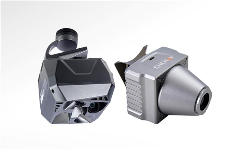
CHC Navigation has released the C5 and C30 orthographic and oblique cameras for aerial surveys. The systems are designed to provide high-quality imaging solutions for photogrammetric applications and to complement lidar survey data.
The C5 camera is an efficient and lightweight system for aerial surveys, weighing 290 g for increased flight endurance. Its compact size of 75 mm x 63.5 mm x 102.5 mm allows easy integration into UAVs. The C30 camera’s weight is 600 g with a size of 110mm x 108 mm x 85 mm. The C30 is also designed for aerial surveying.
The C5 and C30 cameras’ universal installation design makes them compatible with a wide range of fixed-wing and rotor UAV platforms. Both cameras are supported by the CHCNAV’s BB4 Mini and P330 Pro UAVs as well as the DJI’s M300 RTK.
The Alphaport (the A-type hardware interface) enables the C5 and C30 to be easily mounted into various UAVs and converted into the DJI Skyport connector for extended compatibility.
The C5 and C30 cameras give maximum flexibility for photogrammetric applications. They can be used independently on real-time kinematic-enabled UAVs to capture high-resolution imagery or installed directly on the CHCNAV’s lidar series to colorize point cloud data. This feature allows seamless imagery and lidar data integration for a more complete view of the surveyed area.
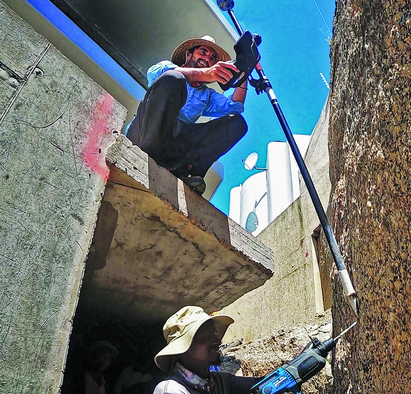
For tough shots in complex construction sites, Lee Landman says that tilt make impossible shots possible. (Image: Lee Landman)
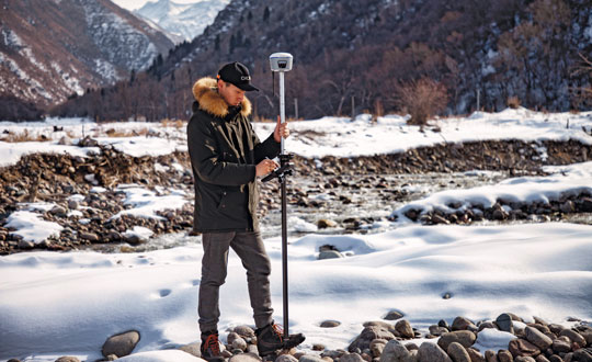
Prior to the advent of tilt compensation for surveying and construction GNSS rovers, there were incremental approaches to tilt, with limited success. However, five years ago, “no-calibration tilt compensation” was first incorporated as a standard option for rovers. Some users remain skeptical or exercise the same caution as they did when such innovations as EDMs were first introduced. Nevertheless, the adoption of tilt compensation — for appropriate tasks — has spread rapidly. How did we get to this point?
For centuries, plumb bobs and bubbles were the only viable options to level an instrument or pole about a point. Early references to spirit levels appeared in the 15th century; however, siphon style water levels may have been in use in ancient Greece, China, and elsewhere for much longer. In more recent centuries, various types of level vials became a standard feature for surveying transits, theodolites and levels. Vials with a slight upward curve position a bubble between defined center marks when level.
Circular, convex glass bubbles appeared for industrial applications in the 19th century and were soon incorporated into surveying instruments and survey poles. In recent decades, electronic bubbles, or “e-bubbles” emerged, using microelectromechanical (MEMS) tilt sensors along with various methods to apply an orientation to compute the position of the pole tip relative to the phase center of the GNSS antenna. This is in contrast to relying on a bubble alone to orient the phase center directly above the pole tip.
There are both pitfalls and potential productivity losses if the pole has to be leveled solely with a bubble for each measurement; we’ll examine these later. If freed from the bubble — as electronic bubbles, tilt sensors, and various methods for orientation enable — how much productivity gain can be realized? For which tasks do the users find tilt compensation most useful? For which do they not? We talked with manufacturers, dealers and field users to find out.
Early adopters
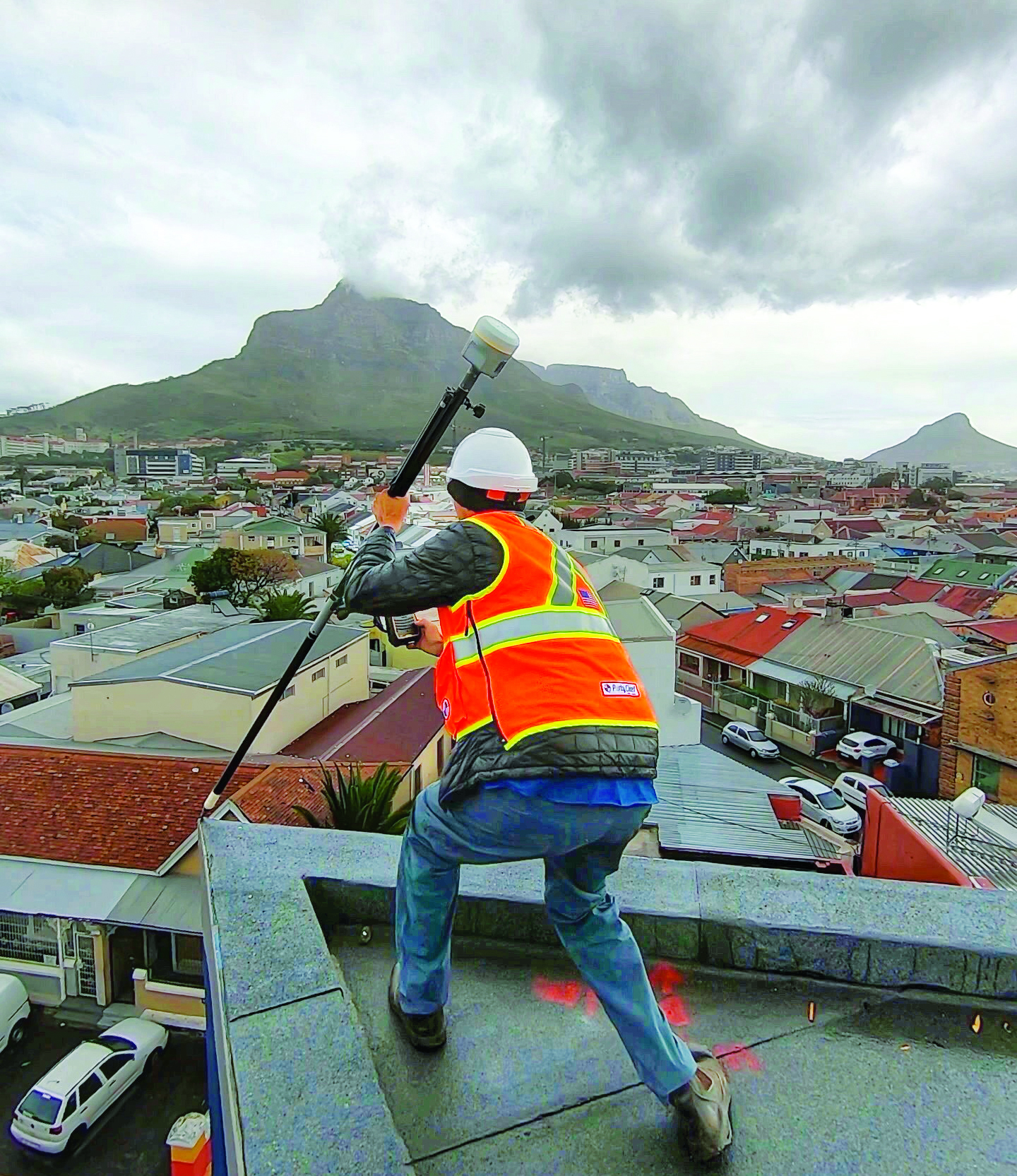
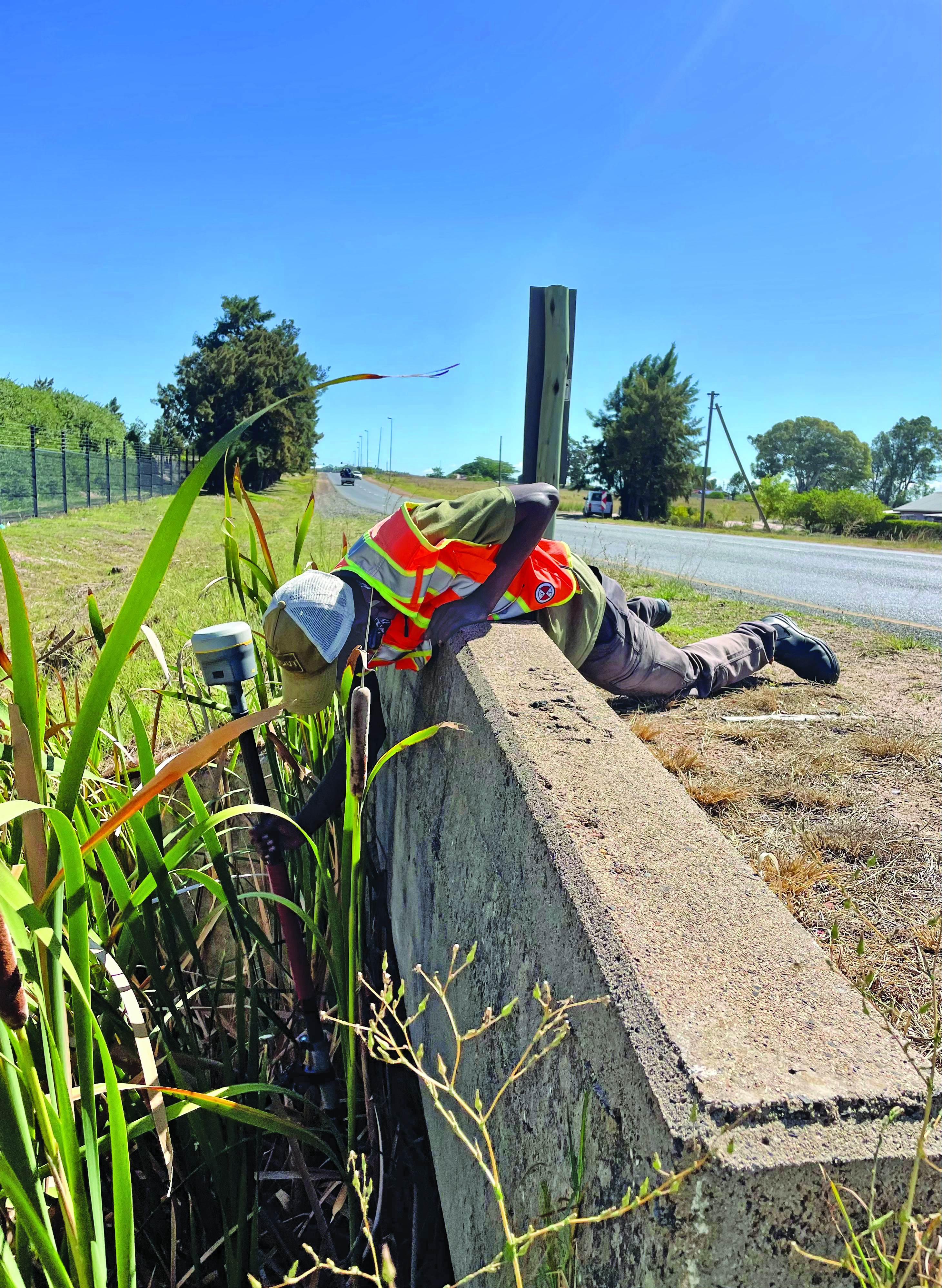
Tilt for safer surveying. (Image: Lee Landman)
Lee Landman owns a firm in the Cape Town area of South Africa that provides construction layout, civil engineering layout and related topographic mapping services. Landman obtained a Trimble R12i GNSS rover, with no-calibration tilt, shortly after its release in 2020.
“Tilt is my go-to tool for almost all tasks now, except layout that needs better than 15 mm to 20 mm tolerance,” Landman said. “For topographic mapping, I will get everything possible with tilt, and then use a total station to get the points I can’t with the rover.”
Landman reports productivity gains of 30% to 50% on certain jobs. His crews will try to leverage a tilt rover for as much of a job as they can, provided it meets precision needs. For checking work, such as grade checking or layout verification, they will try to use tilt for everything first. Then in any areas that look suspect, they will set up a total station to confirm. He said this saves a lot of time up front.
After several years of use, Landman said there are specific tasks where they will not use tilt, and we find this echoed by other users interviewed (and from my own tests). For instance, construction layout of such structures as walls and columns where a consistent 5 mm to 10 mm tolerance is required. He said the same applies for tasks where precise elevation is key, such as on road curbs and final road levels. However, he noted: “That’s a GNSS precision thing, not a tilt issue.”
Landman provides other caveats,“I am nervous using tilt on long rods or when you constantly change rod height, as the results of using a wrong rod height would be disastrous, and the deflection on long rods could also degrade the results.”
Summarizing the overall impact on his operations, Landman explained, “We have become more competitive. Not by sharpening our price, but by the fact that using tilt is less fatiguing and faster to do layout and data collection. That gives us an edge over firms that are not using it.” He provided the example of a foundation layout that needed 300-400 points laid out and chalked in an hour or two so that the excavators that were standing by could start digging as soon as possible. “It normally takes two to three moves of the pole and bubble checks to get a point on position without tilt,” Landman said. “Now, when you are doing 300 points, that is 600-900 times that I don’t have to look at the bubble and adjust the rod. The amount of energy and fatigue that saves is just outstanding. No sore lat muscles and eye fatigue.”
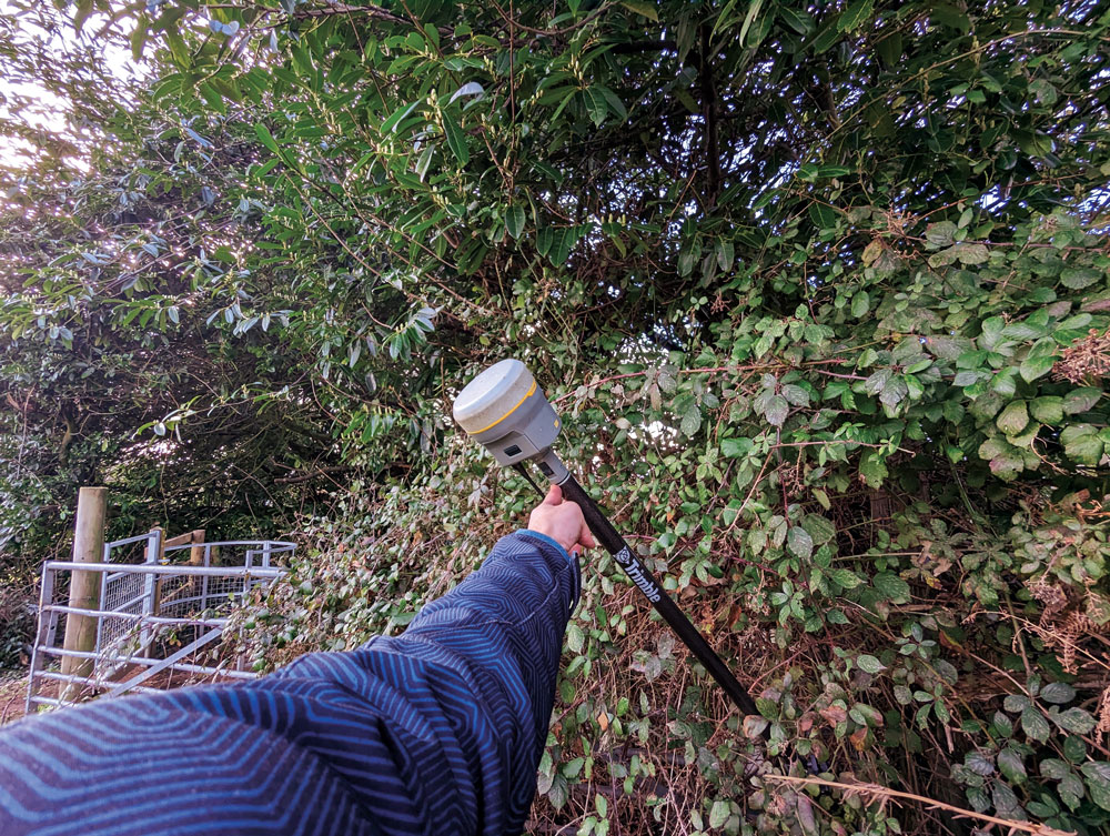
In the southwest of England, where Benchmark Surveys operates, fields and roadways are often lined with thick brambles, making if difficult to shoot features underneath them, such as utilities. James Richards of Benchmark says tilt has revolutionized the way they survey, enabling shots in places where even a total station (where the rod needs to be plumb) cannot take them. (Image: Benchmark Surveys)
Then there are shots that you cannot get with a bubble plumbed pole, Landman said. For instance, in checking rebar layouts prior to construction, as well as marking out on or below the steel rebar cages for plumbing points, voids and slab penetrations.
“Previously we could not easily do this, as you cannot get the pole plumb for total station shots or GNSS to place or check a point,” Landman said. “You just have to check positions on the steel for a column or wall to see if it has enough concrete cover or is in the right position prior to pouring concrete.”
James Richards is the survey manager for Benchmark Surveys, a family-owned and operated firm in the southwest of the UK that has steadily grown its portfolio of services. In part, this growth has resulted from their willingness to embrace new and emerging technologies. This included adding tilt compensated R12i rovers to their instrument inventory shortly after they became commercially available.
“We use tilt on every surveying task where we can use GNSS,” Richards said. “Tilt has enabled us to complete numerous jobs where we would have otherwise only been able to use a total station.” Apart from control, there are not many tasks for which Richards would not recommend using tilt, “It has helped improve our surveys. We can capture data quicker and easier than before and with greater accuracy.” Examples of daily challenges his crews face include getting shots in and around ditches, field boundaries, and boundary fences in foliage, and walls with foliage overhang. These are now easily captured using tilt.
“Tilt has had an enormous impact on our business. We complete work to a higher standard, capturing data quicker and easier,” said Richards. “It helps us capture data that was not possible without offsets. We’ve seen a rise in profitability since using tilt. Surveyors seem to be happier with day-to-day work, knowing that they can capture the data required to meet our high standards, and clients are also happier when receiving more data than expected from surveys.”
Stages of adoption
CHC Navigation is a GNSS developer and manufacturer that has sold hundreds of thousands of units over the past 15 years. They were quick to develop and implement tilt compensation technology, which has now become standard on all of their current models.
Rachel Wang, product manager of CHC Navigation’s Surveying and Engineering division explained the four stages they undertook in developing tilt.
“In the first stage,” said Wang, “users had to rely on the survey pole’s bubble to maintain a centered state, which had significant limitations in terms of measurement accuracy and accessibility.”
In addition to any GNSS error, there could be additional error due to a poorly calibrated bubble, a pole that is not straight, misalignments with each joint of telescoping rods, and user error in trying to keep the bubble lined up while simultaneously operating the field collector (if not using a bipod). Often it seemed that a surveyor would need extra hands and an extra set of eyes.
“The second stage introduced the first generation of tilt compensation using an electronic compass,” said Wang. “Although this technology enabled the first tilt measurements, it was hampered by problems such as low accuracy, tedious calibration, poor reliability, and susceptibility to interference from electrical currents or magnetic fields.”
Common applications for tilt features include getting shots up against structures and improving sky view. For example, for this bridge column with sky partially obstructed by the bridge deck. (Image: CHCNAV)
Such magnetic oriented tilt compensation had been implemented on rovers several years prior to no-calibration methods, by manufacturers that included Javad, Trimble, Topcon, and others. The calibration step often involved rotating the rover vertically in eight or more horizontal positions. This was cumbersome, and the orientation quality changed over time, mostly unbeknownst to the user. It was no surprise that “mag tilt” never really caught on, and unfortunately it made some users wary of tilt in general, even when no-calibration solutions came along.
“The third step was the development of the second generation of tilt compensation, using hybrid positioning based on GNSS + IMU,” Wang said. “This technology was less affected by magnetic interference, but still required initialization of the IMU by shaking the survey pole.” I had tried several models from manufacturers of early “minimal calibration tilt” enabled rovers. For each, a certain amount of movement had to be induced on the pole, by walking around a bit, swinging the pole back and forth, or in a circular sweep. It often did not take more than a minute or so, and then normal moving around on the site would usually keep it calibrated. This was a tremendous step up compared to the old “mag tilt.”
“More recently, we are proud to announce the fourth step in our tilt measurement technology integrated into our new i93 GNSS RTK rover,” Wang said. “Our Auto-IMU technology further simplifies the IMU initialization process by observing acceleration at some point between startup and RTK operation. This replaces the previous repeated shaking of the survey pole for initialization. In fact, users can initialize the IMU while walking or moving normally. In addition, once initialized, the IMU feature is not easily lost even if the pole is carried on the shoulder, held horizontally, or even upside down.”
Wang said that all current CHC survey rovers are equipped with their newest tilt compensation technology. Since the international launch of their first CHCNAV GNSS RTK with IMU, the i90 GNSS in 2019, they have continued to incorporate this feature into all subsequent GNSS rovers. “Based on feedback from users, we know how valuable this feature is,” said Wang. “That is why we have made tilt compensation a standard feature on our current i73, i83, i90 and i93 models.”
Uptake
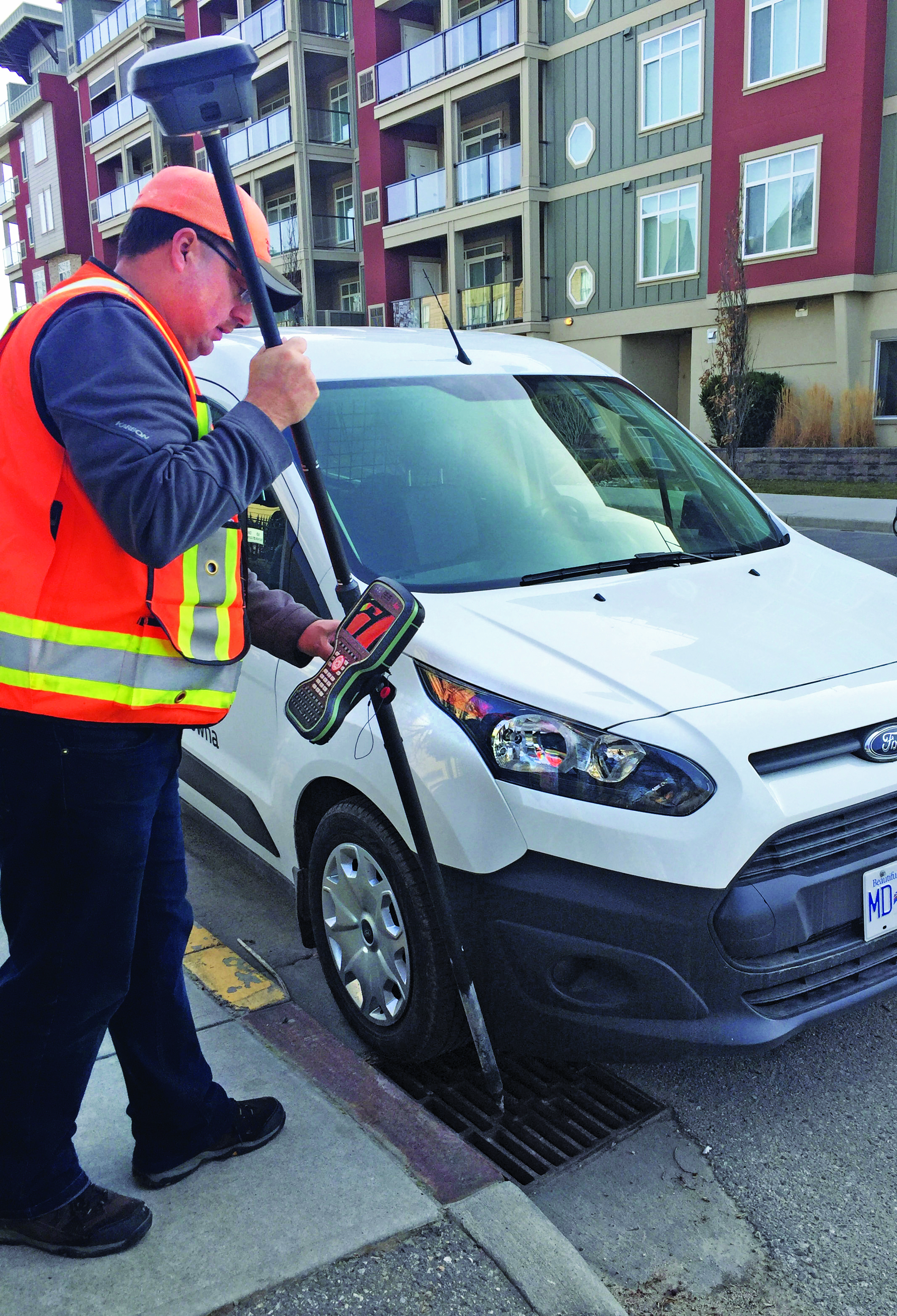
Greg Maier of the City of Kelowna, Canada, was an early adopter of tilt. He found it invaluable to access hard to reach features, such as this inlet under a car, and for safer surveying along the edges of roadways. (Image: Greg Maier)
For the past year, I’ve been talking to other GNSS manufacturers, their dealers, and customers, together with monitoring the subject in surveying and construction groups and forums online. Manufacturers have reported overwhelmingly positive feedback from dealers and customers about the tilt function. Typical feedback focuses on convenience and time savings of not having to level the pole manually.
“Based on our research, we have found this feature to be extremely useful for surveying and staking out on construction sites,” Wang said. “It has increased speed and efficiency by up to 30%.” I have heard similar statistics from each of the manufacturers contacted, as well as their dealers, and most of their customers that have used tilt.
There are common threads to much of the feedback from various sources: the tilt function is now an indispensable tool for many surveying applications.
As Wang noted, “While some users still prefer to use the traditional bubble to plumb the pole, we have seen a clear trend toward adoption of the tilt function in the field. The benefits of tilt, such as faster and easier surveying, are becoming more apparent to our users. As we continue to improve the accuracy of our tilt-compensation, we expect that more and more users will choose this convenient feature over other traditional GNSS rovers in the future.”
Another common observation (no pun intended): even if the pole-tilt feature offers significant convenience and time-saving benefits, it may not be the best option for tasks that require very high accuracy, such as surveying control points. For such tasks, manufacturers, dealers, and users recommend using the traditional bubble on a pole with a bi-pod mount for more accurate measurement.
As something completely new, the uptake across the surveying profession and for construction took time to grow. “It took quite a while to catch on here,” said Keith
Belsham, branch manager for Spatial Technologies, a measurement solutions dealer in the Vancouver region of British Columbia Canada. They specialize in solutions from Leica Geosystems and were an early provider of the Leica GS18 T, widely recognized as the first GNSS rover with no-calibration tilt.
“My perception is that in the United States and some other countries, there are more companies trying to stay at the top of technology,” Belsham said. “However, in our region surveyors are very cautious and need to do a lot of checks and look to see how others respond before they consider it. It was that way with other new technologies; I have memories of numerous total station demonstrations, when prism-less EDM’s were first coming out, where surveyors would pull out a tape measure to check whether the instrument was giving the correct distance.”
About three years after the introduction of no-calibration tilt is when Belsham said it really took off in his region, and it is now quite popular. He gave an example of a customer buying a Leica GS16 (no tilt), saying that they did not see a need for tilt, considering the extra expense. They then upgraded a week later once they were in the field and recognized many instances where the tilt would have saved them time.
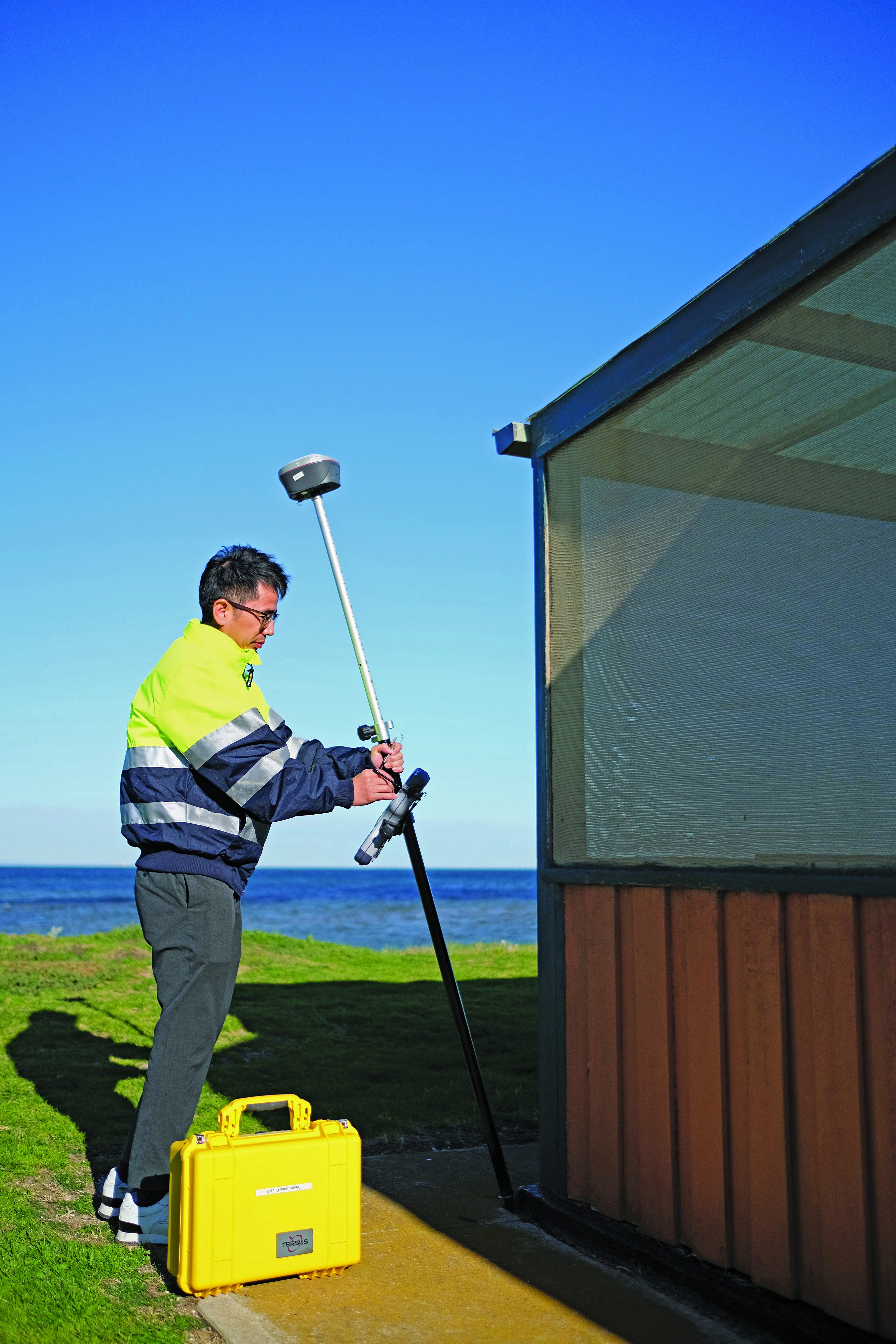
Rather than go the OEM route, Tersus GNSS developed its own GNSS board, positioning engines, and IMU tilt integration. (Image: Tersus GNSS)
A Spatial Technologies customer that has found tilt useful for numerous applications is Lucas Geomatics, a surveying firm based in Surrey B.C. “When I set up GNSS units for construction companies, tilt is great as they don’t have to be super accurate,” said Peter Smith. “I mean, here’s a machine with a bucket that’s 3 f wide, and the bucket is about an inch thick. The grade checked does not have to be super accurate for the machine to hit it, because end users in construction companies do not have to do precise surveying. They’re great guys who dig trenches and tilt gives them more than enough precision for their needs.”
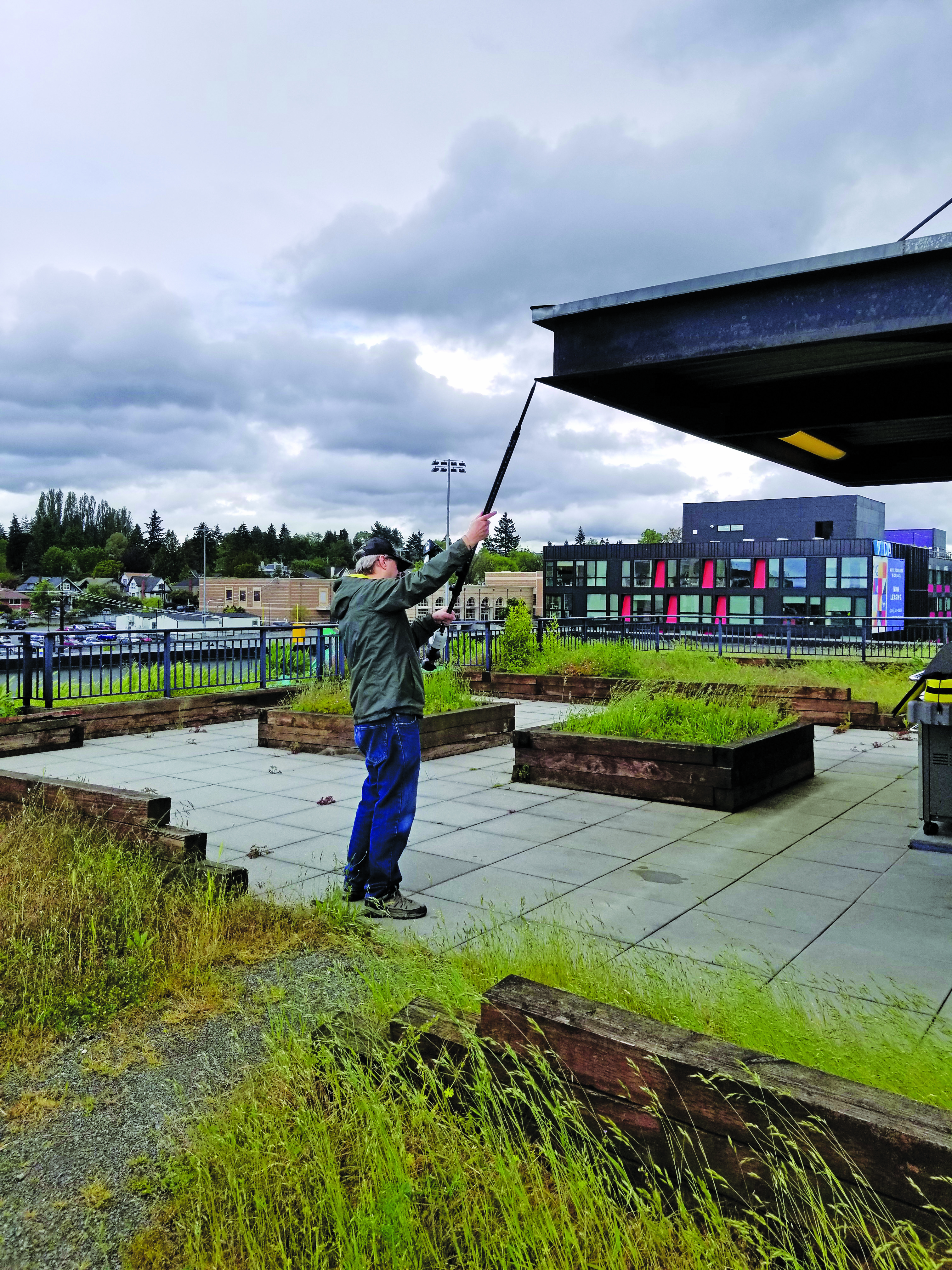
Among the many uses Smith has found for tilt, he has also adapted it in a very creative way to deal with areas of deep foliage. A common approach to working in thick foliage is to raise the GNSS rover up on a tall or extended pole; this can increase the number of satellites viewed and reduce multipath. However, working with a bubble low enough on the pole to see makes it quite difficult to keep the rover at the top sufficiently still and plumbed over the tip. I remember some clever (albeit questionable) solutions folks cobbled together to help plumb very tall poles, such as a small live video camera pointing down over a bubble near the top of the pole to view on a phone. Smith said that tilt solved this problem, and he uses various tall rods, including one that extends to as much as 12 m. He chose a non-conducting pole, such as those used by utility companies for high foliage.
He does prefer to use the rover on a bipod, though, and bubble for control and points requiring very high precision. He sets the data collector software to log positions at 5 Hz or 10 Hz (standard in most systems) and has the software average multiple positions over the course of a minute or more.
Smith said that tilt has made a lot of difference in their surveys, especially where they want a lot of productivity, but do not need very high precision. Part of why he is impressed with the GS18 T is that they had upgraded from an older system, that only used two constellations, to full constellation support on their new rover.
Stability through motion
It sounds counter to one of the key principles for surveying measurement: the instrument and pole must be kept very still. However, in other data collection technologies, including aerial mapping and mobile mapping, leveraging predictable motion, acceleration, and trajectory caught on decades ago. There are numerous integrated GNSS + IMU solutions from, for instance, Applanix and NovAtel, that are the key positioning components for kinematic mapping systems. Such integrated sensor solutions are also in broad use now for UAV real-time and post-processing workflows.
One challenge for integration into survey rovers, was miniaturization. Additionally, such solutions needed a wealth of satellites and signals to be usable at tilted angles. The Galileo and BeiDou constellations reached full complement at about the same time as no-calibration tilt was introduced. Some manufacturers even integrated new antenna designs to better utilize satellites at tilted angles, for example in the Leica GS18 T.
The electronic bubble aspect of such solutions was in some ways the easiest to achieve. Depending on the quality of components, multiple tilt sensors can measure the angle of tilt at precisions matching, or even bettering that of typical pole bubbles. Plus, they are built into the rover boards with a direct relationship to the axis and phase center, whereas the bubble is external, down on the pole.
Integrated IMUs, with as many as nine axes, are highly sensitive, as are accelerometers (if an integration utilizes those). Skeptics always point out that IMUs are subject to drifting over time. However, the observed high-rate GNSS positions and motion sensors are continuously updating the calibration of the IMU. It is true of no-calibration tilt systems that if you hold the pole still too long, it will lose its calibration. Or if you move it too fast. Though on every tilt rover I’ve tried, I moved it around vigorously and spun it (more than would happen in normal operations) and it still kept its calibration. There can also be instances of environments with excessive multipath hazards — such as heavily wooded areas, urban canyons, or congested construction sites — where users often find it best to turn off the tilt for certain shots.
Industry penetration
Tilt for shooting inverts. (Image: Lee Landman)
While manufacturers have approached the GNSS/IMU solution in varied ways, the fundamentals are the same. Once some of the major vendors developed and integrated tilt, they began offering this feature for OEM customers, and in recent years we see tilt on many other brands worldwide. There are relatively new players in the market that took a different approach, developing not only their own GNSS boards and positioning engines, but IMU solutions as well.
Tersus GNSS has rapidly gained a presence in various global markets, though relatively new in North America. While starting as an OEM, the company pivoted to developing its own boards in 2015, and GNSS + IMU integrations more recently. It recently published a paper about what they call its “Extreme RTK Solution” that has a section with data from their own tests for both plumbed and tilted observations.
I did some quick tests with a Tersus Oscar Ultimate, at various angles of tilt, and in mixed environments. The results aligned closely with those in the paper, as did tests with other tilt rovers. I have had the opportunity to try rovers of several different brands, to check precision at various tilt angles against points established with static observations (to see how much the tilt added to the total error). While these were not comprehensive tests, I did compare notes with surveyors who did their own tests, and we’ve all been finding out the practical limits of tilt. Perhaps part of why tilt took a while to catch on was that surveyors needed some time with these units in real-world environments, to get a feel for sweet spots for tilt for different tasks that have specified error budgets.
To get an idea of potential productivity gains, I did a small topographic survey of an area I had previously surveyed with a conventional rover, total station, and scanner. The total station and tilt-less GNSS took about the same amount of time — but with tilt it took about half the time. Many variables can and do come into play, but the figure I keep hearing of up to 30% efficiency gain for many applications seems realistic. Certainly, for asset and resource mapping, tilt could easily fit the looser precision requirements.
As for degradation at various angles of tilt, checks against static points (beyond standard GNSS error) showed negligible differences under 5°, 1 cm up to 15°, 2 cm or more around 45°, and 3 cm or more at 60°. This was just a cursory look, and indeed any surveyors that use tilt should do their own testing. I did notice in the data that when doing simple topo shots, just moving around the site, the pole did not often exceed 5°. Therefore, moving around quickly and efficiently for topo, not having to look at the bubble, improves productivity without significantly compromising quality.
Layout, as surveyors and construction folks who use tilt say, can be quite a snap compared to the old “plumb-shoot, move-plumb-shoot, move-again-plumb-shoot, etc.,” process. You simply move the tip of the pole around until you are on the point.
Enabling further sensor integration
Tilt compensation has now extended to non-GNSS tech, for instance Leica Geosystems AP20 prism poles (used with robotic total stations). (Image: Gavin Schrock)
No-calibration tilt, and multi-constellation GNSS, have enabled further developments that may not have been practical otherwise. Leica has since added an image point extraction feature to its GS18I. This marries the tilt and a camera with a clear path to processing the images in the data collector software. With tilt running, and at ranges under 6 meters, you can roughly aim the camera side of the rover toward say, features under an overhang, that you would not otherwise be able to shoot with a GNSS alone. You walk past the features as the camera takes a series of images. Then, in the software, you identify the points in multiple images and photogrammetrically it gives the offset. You can also process the image series into point clouds. There were several attempts at this sort of solution in the past by various brands. However, without tilt it was too cumbersome as you would need to stop and plum for each image in the series. As one user told me, the new image point features are “like having a UAV on a pole.”
Tersus GNSS has taken a slightly different approach to their image point solution. You pick the point you desire in the camera view on the data collector, and then move along as the software automatically identifies the same point in subsequent frames, until it has enough matches from multiple angles to calculate the offset. CHC Navigation has just announced its own image point feature, with a two-camera integration in the i93 Visual GNSS RTK rover.
Pole tilt also has been integrated into non-GNSS solutions. For instance, the recent release of a prism-pole tilt solution by Leica, the AP20. A constant stream of positions of the prism, from the total station, takes the place of GNSS in this application. They’ve also included a rather clever automated pole-height feature.
What could be next? Perhaps small solid state lidars on rovers, or combined lidar/camera solutions such as on an iPhone/iPad, or a tiny SLAM scanner (that could also aid in position stabilization)? Not to mention what might be coming in the not-too-distant future in the realm of quantum sensing.
In considering all feedback about no-calibration tilt, it seems it is very much here and here to stay. There are many who love it and try to use it for everything (perhaps, in some cases, too many tasks). For others, it is conditional love: use where appropriate. While others still hate it immediately, perhaps on principle, though I find those folks typically have never tried it. Legacy tools and methods provide comfort and known levels of risk. New features such as tilt, provided some time is spent gauging its performance and appropriateness for various tasks, can deliver productivity gains that should prompt reevaluation of some long-held assumptions.
A roundup of recent products in the GNSS and inertial positioning industry from the April 2023 issue of GPS World magazine.
TIMING
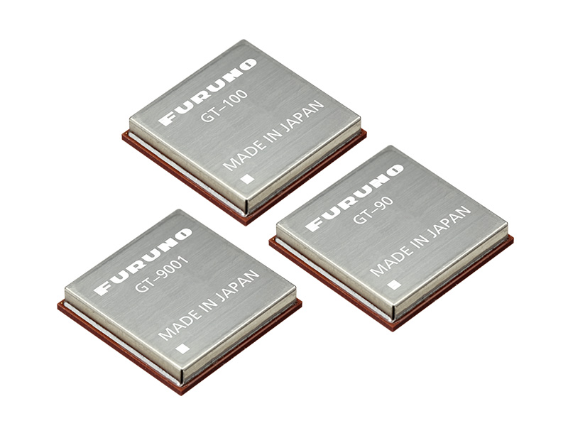
Image: Furuno
Global Timing Module Supports L1 and L5 GNSS signals
GT-100 is compatible with all GNSS constellations. The GT-100 realizes high robustness and standard of time accuracy and stability. The GT-100 features advanced multipath mitigation, anti-jamming and anti-spoofing as well as short-term holdover, ensuring superior performance even if L1 or L5 are jammed. The module delivers nanosecond precision for 5G wireless systems, radio communications systems, smart power grids and grand master clocks. Along with the GT-100, GT-9001 and GT-90 achieve a level of time stability of 4.5ns (1σ) and offer superior features and performance. Furuno, furuno.com
Image: UTStarcom
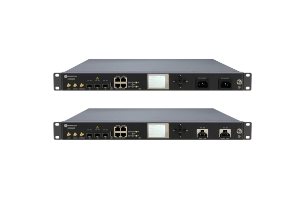
PTP Grandmaster Designed for mobile networks
The SyncRing XGM30E precision time protocol (PTP) grandmaster is designed for mobile networks and other applications requiring accurate time and frequency synchronization. It is an addition to the SyncRing line of network synchronization equipment. The SyncRing XGM30E is an indoor PTP grandmaster offering echo time accuracy of more than ±40 ns, which can meet the stringent timing requirements of demanding applications, including 4G and 5G networks. The clock complies with the PTP IEEE 1588-2008 standard, supporting major ITU-T frequency and phase and time profiles. SyncRing XGM30E supports synchronous Ethernet (SyncE) output on all service interfaces for accurate frequency synchronization, and SyncE input for enhanced time holdover operation during GNSS outages. The grandmaster includes an indoor rack-mount design and power supply redundancy with AC or DC built-in options and has flexible management options. The SyncRing XGM30E is available now.
UTStarcom, utstar.com
Image: Huber+Suhner
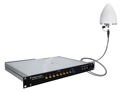
Copper-Free Data System For precise timing synchronization for high-performance networks
The GNSS and Power over Fiber GPSoF System receives, transmits and expands GNSS timing signals for the purpose of timing synchronization in data centers, central offices, distributed antenna systems or enterprise applications. It enables greater distances between the radio frequency source and the receiver system. It is also immune to RFI, EMI and EMP, contains remote control and monitoring via a web interface, and supports infrastructure installation due to direct GNSS signal evaluation.
Huber+Suhner, hubersuhner.com
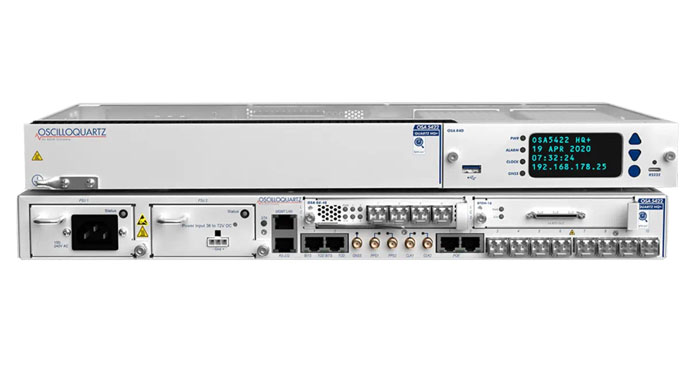
Image: ADVA
M-Code Device With advanced timing for military applications
The OSA 5422 grandmaster clock meets key requirements of military networks by providing advanced positioning, navigation and timing (PNT) capabilities and improved resilience. The OSA 5422 grandmaster clock is integrated with a highly reliable M-code receiver, which meets stringent frequency and phase synchronization needs. The device is equipped with multi-band, multi-constellation GNSS receivers for when M-code is not available. The OSA 5422 also has long holdover and precision time protocol backup, which enables it to maintain accurate timing even in the event of M-code disruption. The OSA 5422 supports legacy interfaces such as BITS and IRIG and features eight field-upgradable 10G bit/s ports and 1G bit/s interfaces. The device is suitable for most demanding military edge applications.
ADVA, adva.com; Brandywine Communications, brandywinecomm.com
AUTONOMOUS
Image: CHC Navigation
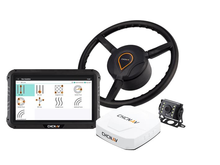
GNSS RTK Steering System Suitable for agriculture applications
The NX510 SE Auto-Steer is an automated steering system that retrofits several types of new and old farm tractors and other vehicles. It can be connected to local real-time kinematic (RTK) networks or GNSS RTK base stations. NX510 SE is a guidance controller powered by multiple corrections sources and five satellite constellations: GPS, GLONASS, Galileo, BeiDou and QZSS. It has a built-in 4G and UHF modem that connects to all industry-standard differential GPS and RTK corrections to achieve centimeter-accuracy steering. NX510 SE contains GNSS and inertial navigation system terrain compensation technology, which maintains high accuracy in challenging environments and terrain. This makes NX510 SE suitable for ditching, planting and harvesting applications. In addition, AgNav multilingual software, operating on a 10.1 in industrial display, supports multiple guideline patterns that include AB line, A+ line, circle line, irregular curve and headland turn. CHC Navigation, chcnav.com
Image: Trimble
Module for Rail Monitoring For automated and semi-automated rail monitoring
The T4D Rail Module enables simple data collection and reduces office work required to automate movement detection for rail monitoring projects. The T4D software offers four main elements for automated monitoring: sensor management and data integration for GNSS; total station, geotechnical, vibration and environmental sensors; geodetic processing and adjustments for accurate results; analysis and visualization through several tools that provide real-time updates to support in-depth analysis and data presentation; and alarming and reporting. The T4D Rail module enables integration of rail as-builts collected with the Trimble GEDO system or with a track measuring bar paired with the Trimble Access Gauge Survey app. It also can automate calculations for track geometry parameters, generate analysis charts, and trigger alarms. The T4D software is offered in five editions to fit various project requirements. The editions include T4D Access, T4D Field, T4D Intermediate, T4D Geotechnical and T4D Advanced. T4D Access and T4D Advanced are the two editions that support the add-on Rail Module. Trimble Geospatial, geospatial.trimble.com
Image: Airobotics
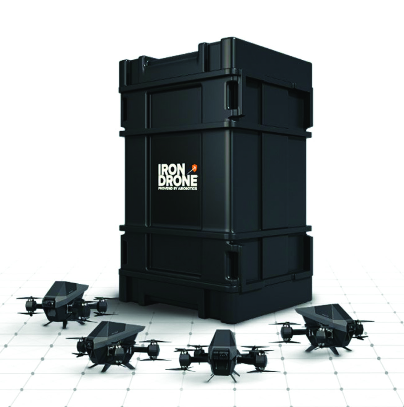
C-UAV Device Anti-UAV protection device
The Iron Drone system is an advanced counter-UAV device, designed to defend against hostile drones in complex environments with minimal damage. Iron Drone is an automated intercepting system designed to eliminate small drones without using GPS or radio frequency jamming. The Iron Drone system is launched from a designated pod and flies autonomously towards targets under radar guidance. It identifies the target using computer vision capabilities. The intercepting UAV follows the target then uses a net and a parachute to incapacitate it, capture it and lower it to the ground.
Airobotics, airoboticsdrones.com
Image: Rohde & Schwarz
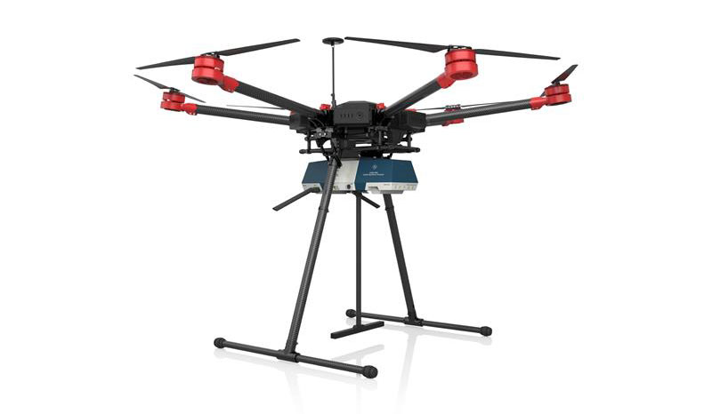
Drone-based analyzer For UAV inspections
EVSD1000 VHF/UHF nav/drone analyzer provides highly accurate UAV inspection of terrestrial navigation and communications systems. The EVSD1000 VHF/UHF nav/drone analyzer is a signal-level and modulation analyzer for medium-sized UAVs. It features measurements of instrument landing systems, ground-based augmentation systems and VHF omnirange ground stations. The mechanical and electrical design is optimized for UAV-based, real-time measurements of terrestrial navigation systems with up to 100 measurement data sets per second. The analyzer provides high-precision signal analysis in the frequency range from 70 MHz to 410 MHz. This also includes the needed measurement repeatability to ensure that results from UAV measurements can be compared to flight and to ground inspections in line with ICAO standards. The EVSD1000 VHF/UHF nav/drone analyzer reduces runway blocking times, provides necessary measurement repeatability and offers measurement precision and GNSS time and location stamps. While streaming measurement data during a drone flight via the data link to a PC on the ground, the analyzer can also buffer data internally to ensure no results are lost if the data link is lost. Rohde & Schwarz, rohde-schwarz.com
SURVEYING & MAPPING
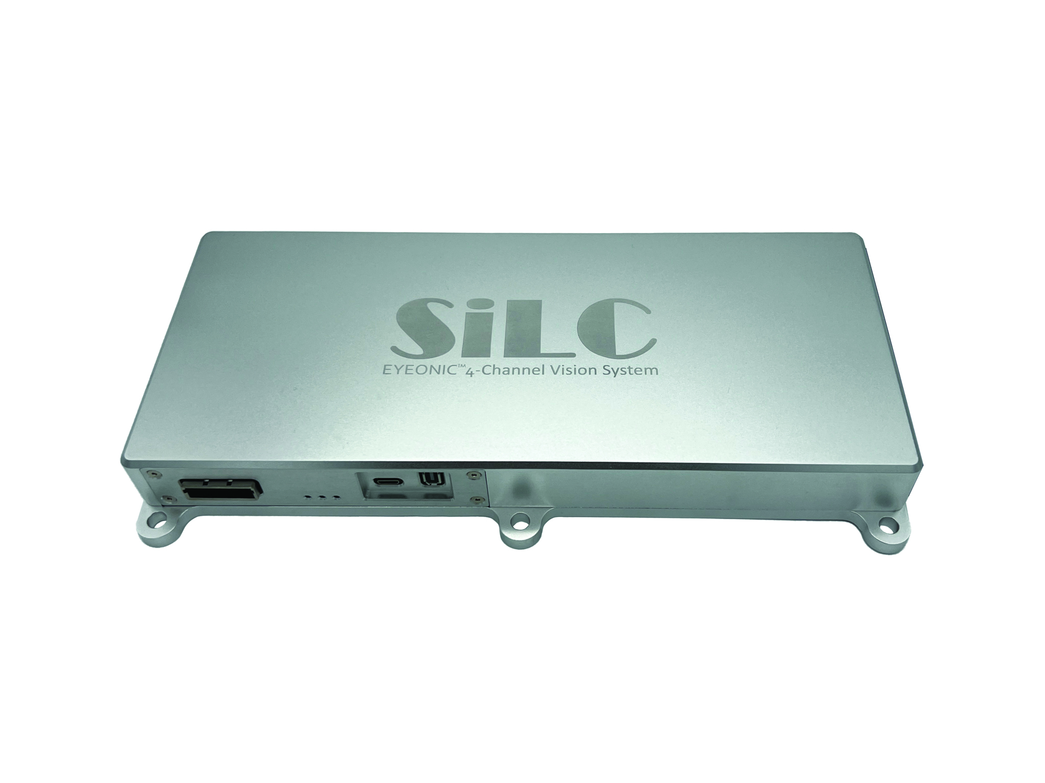
Image: SiLC
Coherent Vision Solution Suitable for advanced products
The Eyeonic Vision System is a frequency-modulated continuous wave lidar solution, which delivers high levels of vision perception to identify and avoid objects with low latency. At the core of the system is a fully integrated silicon photonics chip. It provides more definition and precision than legacy lidar solutions, with roughly 10 milli-degree of angular resolution coupled with millimeter-level precision. These features enable this solution to measure the shape and distance of objects with high-precision and at a large distance. The system combines the Eyeonic Vision Sensor and a digital processing solution based on a powerful field-programmable gate array. The flexible architecture enables synchronization of multiple vision sensors for unlimited points per second. The compact, powerful, vision solution is suitable for autonomous vehicles, smart cameras, robotics and other advanced products. It is available now. Pricing varies depending on configuration.
SiLC Technologies, silc.com
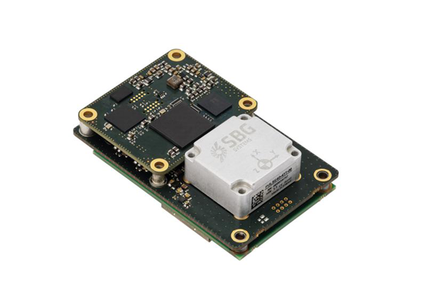
Image: SBG Systems
GNSS-Aided INS Easily integrated with lidar or other third-party sensors
Quanta Plus is a GNSS-aided inertial navigation system (INS). The device combines a MEMS inertial measurement unit (IMU) with a resilient GNSS receiver to get reliable position and attitude, as well as providing real-time kinematic (RTK) fixes. Quanta Plus includes motion profiles, which enable users to optimize the sensor parameters to suit different use cases. The built-in precise time protocol server ensures sub-microsecond synchronization with external devices such as lidar. The device also has a built-in datalogger, Ethernet interface for easy integration, and a web configuration interface for simple setup and control. The INS can be integrated with Qinertia, SBG System’s post-processing software. Qinertia improves the performance of acquired data during a mission using reliable RTK corrections from a wide range of continuously operating reference station networks, or by importing base-station data during the process. Quanta Plus also improves the accuracy of the position and attitude using forward and backward processing and by integrating a tight coupling between GNSS and IMU data. SBG Systems, sbg-systems.com
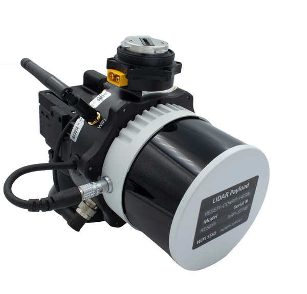
Image: Inertial Labs
Survey Laser Suitable for remote-sensing applications
The Resepi Hesai XT32 laser is designed for accurate remote-sensing applications. It can be used with commercially available lidar scanners, including Velodyne, Quanergy, Ouster, RIEGL, LIVOX and Hesai, as well as with UAVs. Resepi is completely modular, so users have full control for customization. The remote-sensing device uses a GPS-aided inertial navigation system with a NovAtel RTK/PPK single- or dual-antenna GNSS receiver, integrated with a Linux-based processing platform. It also comes with a 2 TB USB memory drive and has an embedded Wi-Fi cellular modem. Resepi has 3 cm to 5 cm point-cloud accuracy and can reach heights of more than 200 m above ground level. It is compatible with most UAV models; however, it is typically used with DJI M300, DJI M210 or DJI M600 models. The device is suitable for scanning and mapping, precision agriculture with lidar, simultaneous localization and mapping algorithm development, utility inspection and construction site monitoring. Resepi-supported software includes Hexagon NovAtel, PCPainter and PCMaster. Inertial Labs, inertiallabs.com
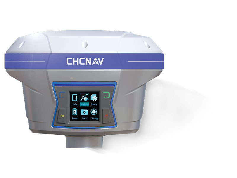
Image: CHC Navigation
IMU-RTK GNSS Receiver Provides robust and accurate positioning
The i90 GNSS receiver combines a GNSS real-time kinematic (RTK) engine, a high-end inertial measurement unit (IMU) sensor and advanced GNSS tracking capabilities to increase RTK availability and reliability. The embedded 624-channel GNSS receiver is compatible with GPS, GLONASS, Galileo and BeiDou signals. The i90 GNSS combines high-end connectivity modules: Bluetooth, Wi-Fi, NFC, 4G and a UHF radio modem. The internal UHF radio modem allows long-distance base-to-rover surveying up to 5 km. The built-in IMU ensures interference-free and automatic pole-tilt compensation in real time. An accuracy of 3 cm is achieved with pole-tilt range of up to 30°. The i90 GNSS receiver is suitable for construction and land surveying projects. CHC Navigation, chcnav.com
Image: CHCNAV
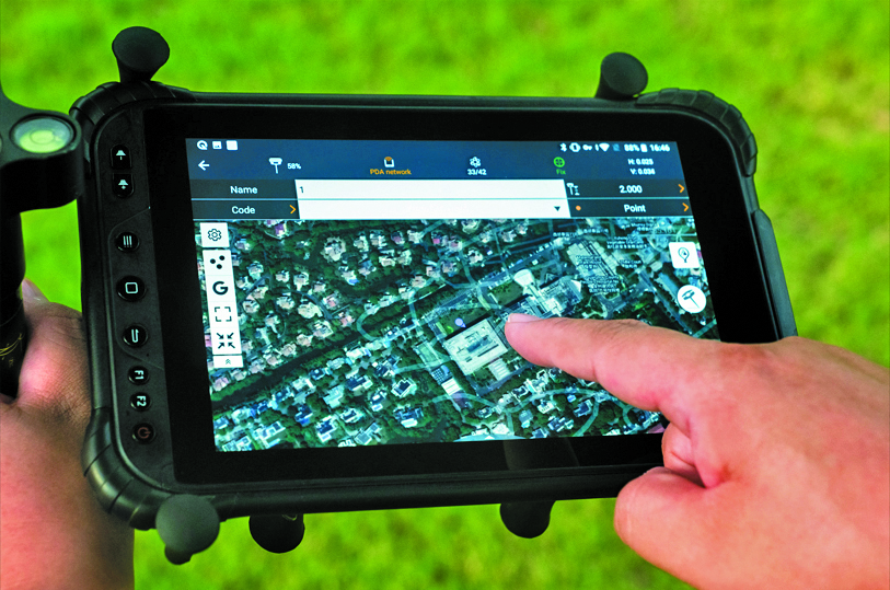
Field Application For Android devices
LandStar8 is designed to be flexible and user-friendly for surveying and mapping tasks. It is versatile, modular and customizable for topographic tasks such as surveying, stake out, cadastral, mapping and geographic information systems (GIS). Building on the legacy of LandStar7, the LandStar8 provides features such as a refined user interface, streamlined workflows, faster operation, and integrated cloud services. Cloud connectivity is built in for backup, data storage or remote technical support. LandStar8 has a simple and intuitive layout with large map windows and sharp graphics. Users can hide features they rarely use and display only those they need. They also can copy coordinate settings, control and staking points from another handheld controller by scanning a QR code. Projects can be edited and sorted by history and attributes. Custom coordinate systems, geoid models and coding libraries can be updated at any time by using resource packages. LandStar8 also features a terrain calibration wizard designed for non-expert users. CHCNAV, chcnav.com
Image: Position Partners
Survey Rover For accurate, survey-grade aerial mapping and photogrammetry
SmartSurveyor facilitates accurate, survey-grade aerial mapping and photogrammetry without the need for a connection between a camera shutter and a GNSS receiver. The fully compact, handheld aerial mapping survey rover is compatible with DJI Mavix 2 and 3 series and Phantom 4 Pro UAVs. The design is dissimilar from other UAV mapping systems in that it works from a UAV or smartphone and with two or more ground control points (GCPs) while using an ultra-matching technique. Once SmartSurveyor captures data, all photos and the GNSS file are uploaded to a PC and analyzed through the Agisoft UltraMatch workflow to confirm their accuracy before they are exported. Data can be managed in the cloud or on a local PC using software designed by MapSender. Additionally, this mapping tool works in tandem with the AllDayRTK subscription GNSS network service so that collected data can be uploaded to Tokara to remotely manage a project.
NB-IoT Industrial Module Complete with GNSS geo-location capabilities
Image: STMicroelectronics
The ST87M01 is a fully programmable, certified LTE Cat NB2 NB-IoT industrial module that covers worldwide cellular frequency bands and integrates advanced security features. The ST87M01 is an integrated native GNSS receiver with multi-constellation access, which ensures enhanced and accurate localization. The module has a diminutive 10.6 mm x 12.8 mm land grid array footprint, making it suitable for applications where a small form factor is key. The STM8701 offers flexibility for product developers, presenting a fully programmable internet of things (IoT) platform enabling users to embed their own code into the module for simple applications. A variety of protocol stacks are available to handle popular IoT use cases. It targets wide-ranging IoT applications that require ultra-reliable low-power wide-area network connectivity and has ultra-low power consumption with less than 2 µA in low-power mode and transmit output power up to +23 dBm. Suitable applications for the module include smart metering, smart grid, smart building, smart city and smart infrastructure applications, as well as industrial condition monitoring and factory automation, smart agriculture and environmental monitoring. The module also can be combined with a separate host microcontroller, permitting many more use cases. STMicroelectronics, st.com
Image: Quectel
GNSS Module Designed for battery-operated, ultra-low power GNSS devices
The LC76G module is a compact, single-band, ultra-low power GNSS module that features fast and accurate location performance. The module can concurrently receive and process signals from the GPS, GLONASS, BeiDou, Galileo and QZSS constellations. The LC76G has an internal surface acoustic wave filter and integrated low-noise amplifier, which can be connected directly to a passive patch antenna and provides filtering against unwanted interference. With a compact size of 10.1 mm × 9.7 mm × 2.4 mm, the footprint of the LC76G is compatible with other industry solutions, as well as Quectel’s legacy L76 and L76-LB modules. The LC67G is designed for battery-operated, ultra-low power GNSS devices, such as wearable personal trackers, wildlife and livestock tracking, toll tags, portable container trackers, as well as several traditional markets such as shared mobility and low-cost asset trackers. Quectel Wireless Solutions, quectel.com
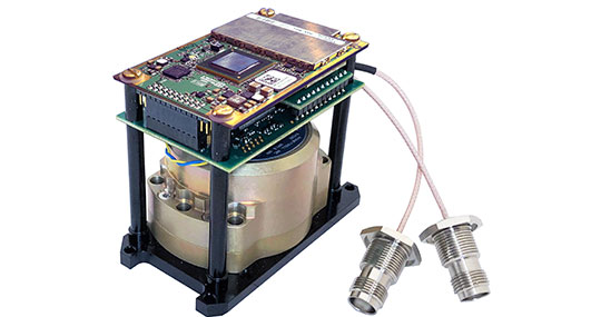
The INS-DH-OEM. (Photo: Inertial Labs)
Inertial Navigation System Incorporates NovAtel and Honeywell technology
The INS-DH-OEM utilizes a dual-antenna NovAtel GNSS receiver and a Honeywell HG4930-CA51 inertial measurement unit (IMU). The INS-DH-OEM contains Inertial Labs’ on-board sensor-fusion filter, navigation and guidance algorithms, and calibration software. The INS-DH-OEM has three axes, a full operational temperature range, advanced MEMS accelerometers and new-generation tactical-grade MEMS gyroscopes to provide accurate position, velocity, heading, pitch and roll. It is small and lightweight, measuring 85.5 mm x 67.5 mm x 52.0 mm and weighing 280 g. The dual-antenna NovAtel GNSS receiver is operational with GPS, GLONASS, Galileo, BeiDou and QZSS constellations. The INS-DH-OEM is compatible with most commercially available lidars including Velodyne, Riegl and Faro. The algorithms are suitable for different dynamic motions of vessels, ships, helicopters, UAVs, gimbals and land vehicles. Inertial Labs, inertiallabs.com
Image: MSO
Speed Sensor Multi-use sensor for workflow
The Speed Wedge MKII is a true-ground speed sensor and active motion detector for moving objects, based on radar doppler technology. This sensor is suitable for use in indoor and off-highway vehicles, conveyor belts, material flow and open channel water surface flow. The sensor contains a dead-reckoning system component for inertial measurement units and integrated management systems (IMS) in GPS/GNSS-denied environments such as in tunnels and underground mining operations. It also features sensor fusion with GNSS and IMS improving positioning accuracy, quality and reliability. Speed Wedge MKII deploys a radar front-end with planar antennas continuously emitting electro-magnetic waves at 24 GHz. It is designed for contactless measurement of speed and distance travelled independent on wheel/drive slip. For demanding applications Speed Wedge MKII is sealed and potted in a rugged encasing. Speed Wedge MKII is available in variants with pulse, serial RS232 and CAN-Bus output. High-speed up to 200 km/h is available.
MSO, mso-technik.de/home-en.html
Image: Orolia
GNSS Simulations Software For simulation and testing needs
Skydel GNSS simulation software can now generate more than 500 simulated satellite signals. This platform is suitable for GNSS users, experts and manufacturers, as well as users needing a low-Earth-orbit-capable simulation system. Skydel contains a feature that includes multi-constellation and multi-frequency signal generation, remote control from user-defined scripts, and integrated interference generation. In addition to generating a high channel and satellite count, Skydel also can produce navigation warfare signals without any additional hardware. Orolia, orolia.com
Image: Mikroe
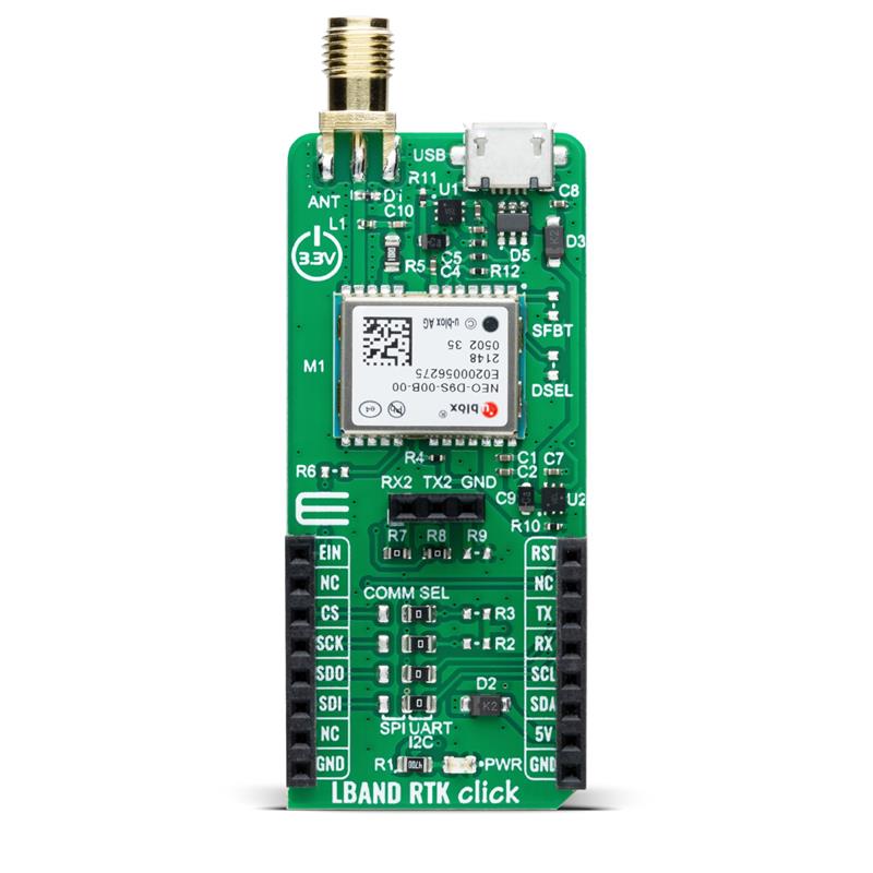
Compact Add-On Board Provides access to L-band GNSS corrections
LBand RTK Click is a compact add-on featuring the NEO-D9S-00B, a professional-grade, satellite data receiver for L-band corrections from u-blox. Operating in a frequency range from 1,525 MHz to 1,559 MHz, the NEO-D9S-00B decodes the satellite transmission and outputs a correction stream. This enables a high-precision GNSS receiver to reach accuracies down to centimeter-level. An independent stream of correction data, delivered over L-band signals, ensures high availability of position output. LBand RTK Click also uses several mikroBUS pins. In addition, LBand RTK Click contains an SMA antenna for connecting a Mikroe-brand antenna. This antenna easily allows positioning in space, supporting GNSS L-band frequencies. LBand RTK Click implements advanced security features such as signature and anti-jamming mechanisms. It also can be integrated with other GNSS receivers from the u-blox F9 platform. Mikroe, mikroe.com
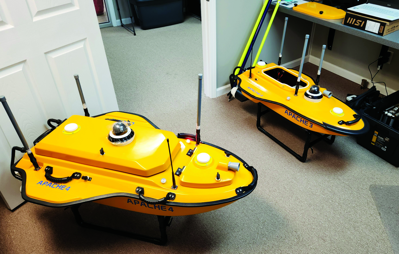
To improve the efficiency of their hydrographic surveying services and expand them, Coastal Geomatics evaluated multiple USV, choosing the CHC Apache 4. (Image: Coastal Geomatics)
Time (and costs) saved using unmanned surface vessels (USV) over conventional methods for hydrography can be dramatic — especially in autonomous mode. Numerous firms, large and small, have discovered how modest investments in such craft can completely revolutionize their hydrographic operations. One such firm is the family owned and operated Coastal Geomatics in North Carolina.
“With conventional methods, it used to take us four weeks with a three- or four-person crew to do the bathymetry for 26 canals that we do every two years for the City of Holden Beach,” Chris Stanley, owner and manager of Coastal Geomatics, said. “Now, with our Apache we do this over four days of high tide; about four to five hours per day.”
Stanley had been surveying in the local area for more than 30 years and had partnered in several local firms. In 2020, he decided to start his own firm, together with his two adult sons Alan and Ian: Coastal Geomatics was born.
“We do a lot of boundary work, and topographic surveys as there is a lot of construction going on in the area,” Alan said. “We also do flood insurance work, FEMA elevation certificates, and hydrographic work — we are on the coast.” Holden Beach is on one of North Carolina’s barrier islands, separated from the mainland by the Intercoastal Waterway. Coastal Geomatics has standing contracts to do hydro work for FEMA beach erosion annually, and the biennial canal surveys for the city.
The move to a USV for hydrographic surveys made a lot of sense, however a past bad experience with the technology prompted Stanley to be extra diligent in choosing a boat. At one firm for which the elder Stanley had worked in the past, they had acquired a USV that he said was essentially “a jet ski, with a mix of components cobbled together.” He added that they had never really gotten it to work right, and it now sits idle in a storage unit.
The Stanleys did some research on the current state of small USV, noting that some still seem like “contraptions” and decided instead to test out three models from CHC Navigation: the Apache 3, 4, and 6. They had considered the tri-hulled Apache 6 for some offshore work they sometimes do, however, they chose the Apache 4 for now. It has a dual GNSS antennas for position and heading that is tightly coupled with an IMU for uninterrupted positions, a single beam echo sounder, and a 360° camera. It has a sensor well that can accommodate most of the popular models of acoustic doppler current profilers (ADCP), though Coastal Geomatics is not presently using an ADCP. It can be run fully autonomously for missions defined in the AutoPlanner software, or remotely piloted — Coastal Geomatics needed both options. They noted how the boat is compact, easy to operate, and all components are well integrated with watertight seals.
For open water areas of their contracted surveys, they put the USV in full autonomous mode, where they say it is quite efficient. However, there are specific tasks where a remote pilot needs to take over.
The canals surveyed for the city to inform dredging operations are about 100 feet wide and each house has a floating dock. There is a 20- to 30-foot strip between the docks. The old method, Ian explained, was to put one of the crew in a small flat bottomed Jon boat, with a crew member on each side of the canal, often with a fourth using a total station. Points across the canal from bulkhead to bulkhead were taken with a long prism pole, handing the pole off to the crew member on the other side after each crossing. The dynamics of which residents’ boats might be at the docks on any given day made full autonomy for that phase of the surveys impractical.
Coastal Geomatics’ solution was to employ a peddle-powered kayak, guiding the Apache remotely. The flexibility of their new craft has enabled the firm to execute multiple types of surveys and expand their hydrographic services more efficiently.
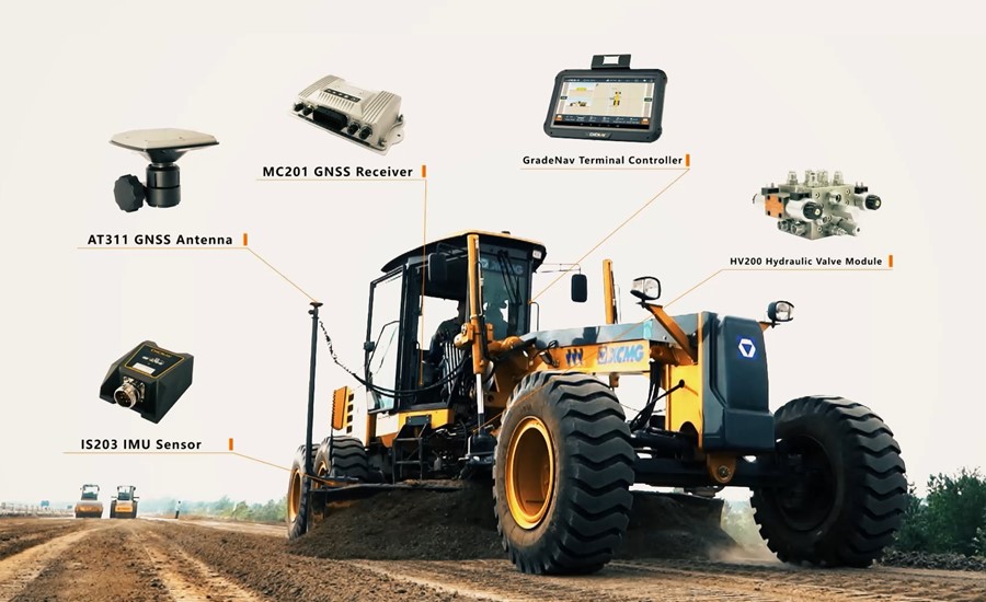
CHC Navigation has released the TG63, a 3D Grade Control System designed for motor graders.
With a tightly coupled dual-GNSS positioning system and inertial sensor, the TG63 provides reliable 3D positioning and heading to ensure accuracy of the grader blade within ±2 cm.
The TG63 is designed to withstand the harsh environment of construction sites and supports multiple applications, including real-time kinematic networked transport of RTCM via internet protocol and ultra-high frequency base stations.
In addition, GradeNav software, operating on a 10.1 in industrial display, supports standard AutoCAD DXF design files to manage multiple grading operations, including surfaces, slopes, TINs and road features.
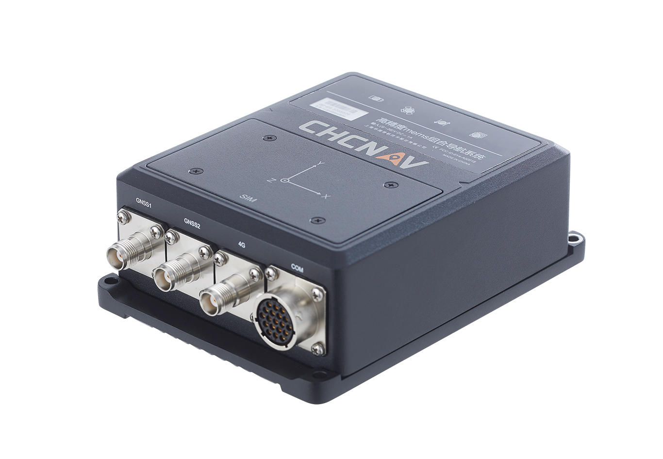
The CHCNAV CGI-610 GNSS/INS sensor is an advanced dual-antenna receiver designed for reliable and accurate navigation and positioning in challenging terrestrial, marine or airborne applications.
Designed to meet the needs of 3D positioning and autonomous vehicle guidance applications, it provides high performance in urban canyons and other harsh environments where GNSS signals are lost or degraded. Incorporating the latest GNSS technology and an industrial-grade inertial measurement unit, the sensor delivers accurate hybrid position, attitude and velocity data up to 100 Hz, driven by CHCNAV algorithms.
Its rugged and lightweight package ensures uninterrupted performance and meets high protection standards.
CHC Navigation has released the NX510 SE Auto-Steer, an automated steering system that retrofits several types of new and old farm tractors and other vehicles. It can be connected to local real-time kinematic (RTK) networks or GNSS RTK base stations.
NX510 SE is a guidance controller powered by multiple corrections sources and five satellite constellations: GPS, GLONASS, Galileo, BeiDou and QZSS. It has a built-in 4G and UHF modem that connects to all industry-standard differential GPS and RTK corrections to achieve centimeter-accuracy steering.
NX510 SE contains GNSS and inertial navigation system terrain compensation technology, which maintains high accuracy in challenging environments and terrain. This makes NX510 SE suitable for ditching, planting and harvesting applications.
In addition, AgNav multilingual software, operating on a 10.1 in industrial display, supports multiple guideline patterns that include AB line, A+ line, circle line, irregular curve and headland turn.
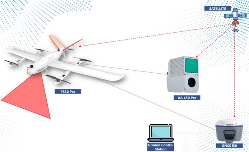
CHC Navigation’s mobile mapping solutions, the P330 Pro vertical take-off and landing unmanned autonomous vehicle (VTOL UAV) and the AlphaAir 450 lidar, are being used for mining exploration in Indonesia. The solutions help with effective data collection to measure the volume of an open-pit mine.
The P330 Pro UAV and the AlphaAir 450 provide an effective surveying solution, which is critical to the life cycle of mining projects. During this operation, the solutions covered more than 5 km² per mission, with an error of less than 5 cm. Accurate lidar in vegetated areas enabled surveying of the ground surface, including structures missed by other surveys due to dense vegetation.
A CHC Navigation i50 GNSS receiver and processing software provided with the AlphaAir 450 were deployed during the operation.
The P330 Pro UAV enables small- and large-scale aerial surveying. It comes with a portable ground control station for remote control and communication between the UAV and its operator. The UAV is designed for vertical takeoff and landing, making it convenient to operate and transport.
The AlphaAir 450 is a lightweight and rugged system, which integrates lidar with an industrial-grade professional 26 MP camera and an inertial navigation system for data collection.
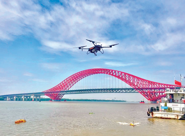
Tactical-grade IMUs enable UAVs to achieve the same locational accuracy as ground-based systems. (Photo: CHC Navigation)
We often hear the anecdote about an early lidar scanner that could take a shot every few seconds, yet it held a value proposition for certain applications. As the capabilities of successive mapping and surveying systems change rapidly, so does the conventional wisdom about which are best for various applications. Transportation corridor mapping — be it for improvements design, as-built surveys, asset management or digital twinning — has always been a balancing act between precision and efficient large-scale data capture.
“I remember 15 years ago, during my university time, the scanner was the size of a dining table,” said Andrei Gorb, segment manager for mobile mapping and unmanned aerial vehicle (UAV) systems, CHCNAV. At the top end of the mapping food chain were terrestrial scanners, targets, bore sighting, and registering point clouds mostly manually. As cumbersome and time-consuming as the legacy tools and methods were, these options still offered efficiency gains compared to conventional surveying with total stations. Then a decade ago, mobile-mapping systems began to change that paradigm. Departments of transportation found that mobile-mapping systems could meet their requirements for many design projects, and certainly for asset inventory and management. Unmanned aircraft systems (UAS) were not quite there yet.
The tech used depended on the application. “First, there was road maintenance, to understand the road condition,” Gorb said. “Previously, UAS did not meet the high requirements: centimeter in absolute and millimeter in relative. We now have mobile-mapping solutions, from us and other suppliers, that can be in the 8-9 mm absolute accuracy range on short road surfaces.” Yet for many transportation applications, the absolute accuracy may not be as important as the relative precision. This is where years of development in UAS has made the difference.
CHCNAV was not alone in recognizing that the gap was closing, and the company planned ahead. “Previously, UAS would fly for under an hour, and were mostly carrying cameras or early lidar, which was not suitable for highways,” Gorb said. “A few years of development, and we see it is practical to meet requirements with UAS flying between 50 and 100 meters — in Europe, many local regulations forbid flying above 120 meters anyhow.” Gorb attributes the advances to lidar sensors that UAS can carry. These sensors have become much better and less expensive. Plus, platforms like vertical-take-off-and-landing (VTOL) systems can stay in the air much longer.
The UAS boom of the past 10 years saw the dominance of consumer-prosumer market UAV platforms becoming quite commoditized, with certain vendors gaining majority market share. CHCNAV, instead, sought to develop enterprise solutions, for both mobile and UAS systems — large-platform rotor, fixed-wing and VTOL platforms. The company offers an amalgam of hardware and software, from Riegl scanner heads on some of their mobile-mapping systems to Honeywell inertial navigation systems (INS) for some of their UAS solutions.
Gorb echoes what we hear from many mapping practitioners, saying ground-control points are not as necessary in the densities required for legacy mobile and UAS mapping. He explained that everything from strip adjustments to processing of GNNS/IMU data has tightened both precision and accuracy. “We have a tactical-grade IMU in both our mobile mapping and UAS solutions, for a high-end trajectory,” Gorb said. “So, it means that we can get the same high-accuracy point cloud for highways from the ground and the air perspectives.”
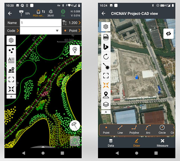
CHC Navigation has released LandStar8, a field surveying and mapping application for Android devices. LandStar8 is designed to be flexible and user-friendly for surveying and mapping tasks.
LandStar8 is versatile, modular and customizable for topographic tasks such as surveying, stake out, cadastral, mapping and geographic information systems (GIS). Building on the legacy of LandStar7, the new LandStar8 provides features such as a refined user interface, streamlined workflows, faster operation, and integrated cloud services.
“With LandStar8, we want to provide our users with unprecedented field experience,” said Rachel Wang, product manager of CHC Navigation’s Surveying and Engineering Division. “LandStar8’s modular design allows users to customize the interface according to their usage habits, making it easier and more efficient for field crews to work.”
Cloud connectivity is built in, for backup, data storage or remote technical support.
LandStar 8 has a simple and intuitive layout with large map windows and sharp graphics. Users can hide features they rarely use and display only those they need.
On LandStar8, users can copy coordinate settings, control and staking points from another handheld controller by scanning a QR code. Projects can be edited and sorted by history and attributes. Custom coordinate systems, geoid models and coding libraries can be updated at any time by using resource packages. LandStar8 also features a terrain calibration wizard designed specifically for non-expert users.
A proprietary MetaCAD graphics engine opens DWG and DXF base maps faster and with smoother rendering. DXF files up to 200 MB can be opened in less than 10 seconds. LandStar8 also supports opening external reference files, automatically recognizes CAD length units, and allows editing of CAD base maps directly in the field.
LandStar8 is designed around a comprehensive cloud-based architecture that supports project backup, collaborative work and data storage. Its remote support capabilities help the office helpdesk resolve user problems and provide personalized technical assistance. A “share code” feature allows users to transfer project data between desktop computers and field controllers or among field controllers quickly to further boost work efficiency.
GNSS receivers face the same old challenges (extremely weak received signal, orbit and satellite clock errors, ionospheric and tropospheric delays, multipath, dilution of precision, urban canyons, etc.) and new ones (increased interference). However, compared with just a few years ago, they benefit from new signals, many more satellites, a panoply of options for corrections, and improved integration with inertial navigation systems (INS).
For example, pole-tilt compensation is quickly becoming standard. This feature enables users to locate dangerous or hard-to-reach points by measuring them at an angle with just the tip of the pole to which the receiver is attached.
Pole-tilt compensation also makes surveying and mapping easier by removing, in many situations, the need to use total stations or offsets. Together with improvements in work processes, this makes GNSS receivers more user friendly. This is particularly welcome now that more surveyors are retiring than there are new surveyors entering the profession.
The greater accuracy of GNSS receivers enabled by the increase in the number and quality of satellites, signals, corrections services and integration of GNSS with other sensors is also increasing the number of use cases, especially at the high end of the accuracy requirements, such as lane-level vehicle navigation. (Next month’s cover story will center on this year’s Google Smartphone Decimeter Challenge contest, in which competing teams aim to bring smartphone location down to the decimeter or even centimeter resolution using raw location measurements from Android smartphones. This could enable services that require lane-level accuracy, such as estimated time of arrival when using a high-occupancy vehicle lane.)
This month’s cover story highlights what has changed “inside the box” to improve the accuracy and resilience of GNSS receivers for surveying, mapping and a variety of other applications. Read the success stories from five different companies below.
An interview with Rachel Wong, product manager, surveying and engineering division at CHC Navigation about recent GNSS receiver innovations.
Wong
What was the most significant technical innovation in your GNSS receivers in the past five years?
CHC Navigation is a technology enabler for geospatial professionals in more than 120 countries. End users of geospatial data increasingly come from diverse backgrounds. This forces us to invest heavily in simplifying data-acquisition processes by focusing on the user friendliness and positioning reliability of our GNSS receivers.
The latest technological developments in GNSS real-time kinematic (RTK) rovers are based on the maturity and improvement of satellite navigation systems, as well as on the integration of IMU sensors in the receivers — the latter being certainly the most important innovation.
In addition, the latest generation of our GNSS rovers, such as the CHCNAV i83, is based on the sophisticated iStar algorithm, which significantly improves the efficiency of tracking GNSS satellite signals for unmatched performance in GPS, GLONASS, BeiDou, Galileo and QZSS constellations, using all available frequencies including BeiDou 3. This goes hand-in-hand with the integration of the IMU as it helps to ensure increased GNSS positioning accuracy through optimized satellite geometry.
What has it enabled users to do that they could not do before?
A utility worker uses the tilt-pole-compensation feature to measure a manhole. (Photo: CHC Navigation)
The integration of GNSS+IMU modules allows surveyors to survey points without the need to level the range pole, accelerating the adoption of GNSS technologies for early adopters by simplifying work processes. For example, our i83 GNSS is powered by a 1,408-channel multiband GNSS receiver, the latest iStar technology and a high-end, calibration-free IMU sensor for faster, more reliable GNSS field surveys.
The i83 GNSS’ integrated IMU automatically compensates for pole tilt, increasing surveying, engineering and mapping efficiency by 30% over conventional RTK GNSS surveying methods. In less than 5 seconds, the 200-Hz inertial module is initialized to ensure survey-grade accuracy over a pole-tilt range of up to 30 degrees that meets the real-world operational needs of our users.
What is a good example of this?
Surveyors can extend their working boundaries near trees, walls and buildings without the need for a total station or offset measuring tools. This can be illustrated in sewer and drainage applications, such as measuring the bottom of manholes for water, utilities or sewers, which was barely feasible in terms of GNSS measurement before the advent of hybrid GNSS + IMU positioning.
Operators only need to concentrate on their tasks and no longer need to level their pole vertically. They are now able to perform many measurements without compromising accuracy and reliability. Productivity is greatly increased, RTK usability is greatly improved, and potential human error is reduced, whether you are an engineer, foreman or surveyor, and whether you are an experienced or new user.