A roundup of recent products in the GNSS and inertial positioning industry from the February 2024 issue of GPS World magazine.
SURVEYING & MAPPING
Handheld GIS Data Collection Solution
For outdoor operations
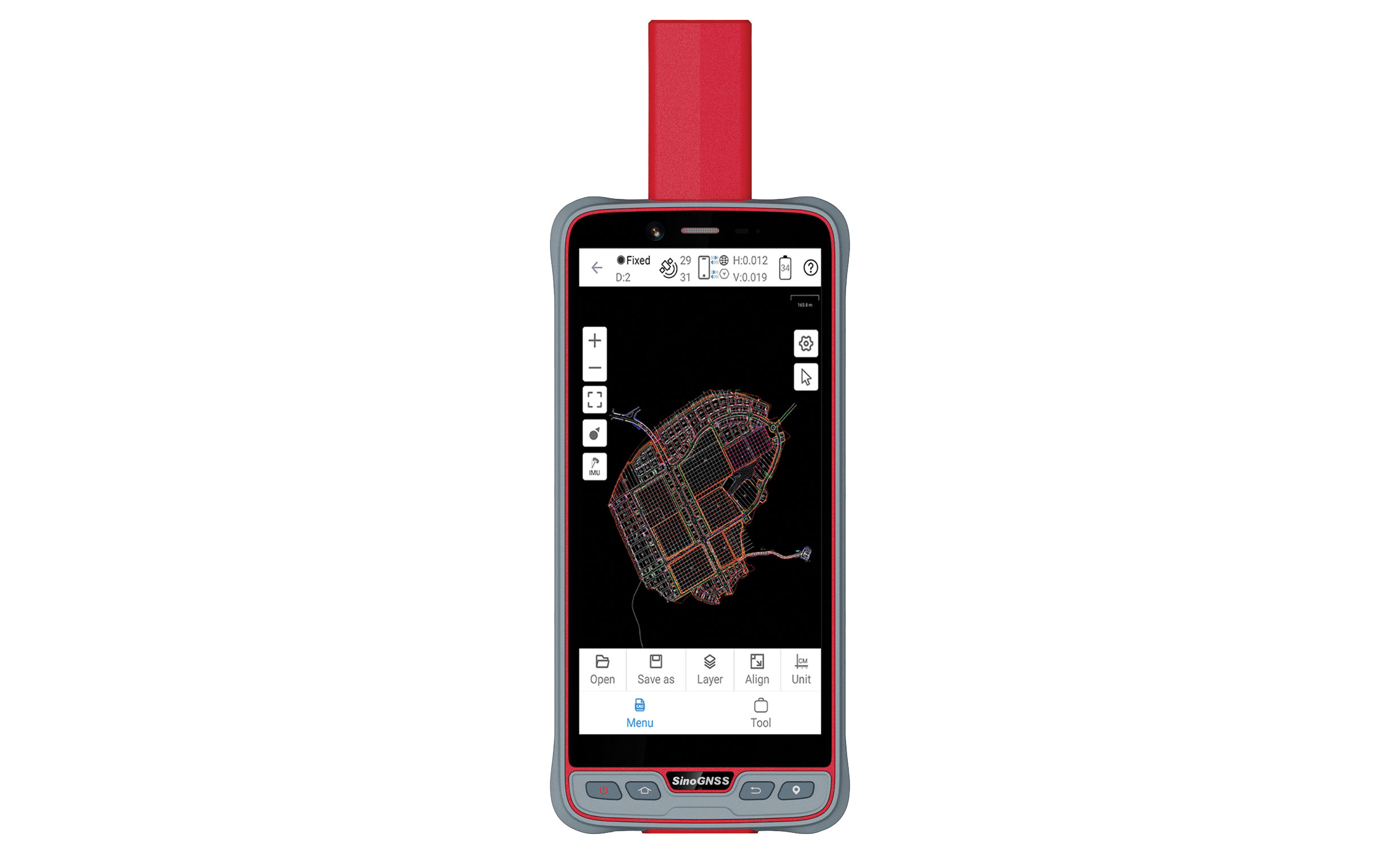
The handheld P6H solution is designed for GIS data collection and outdoor operations. Featuring a GNSS high-precision positioning module, rugged IP67-rated design, and 6-inch sunlight-readable display, the P6H offers positioning accuracy in harsh environments.
Equipped with a SinoGNSS self-developed high-precision K8 board and antenna, it can track all running and planned constellations with 1,590 channels, including GPS, BeiDou, GLONASS, Galileo, QZAA, IRNSS, and SBAS.
The P6H offers users centimeter- or decimeter-level accuracy. Its IP67 rating protects against dust and water to enhance its efficiency and durability in tough environments.
The device comes equipped with Survey Master and robust GIS functions, which allow users to take measurements of geographic elements and store the results as attribute data for subsequent analysis, calculation, and visualization. It also includes a mock location function for users to accurately share Survey Master’s position with P6H. The location data can then be accessed on a third-party GIS software.
It is also compatible with common GIS software such as ArcGIS Collector, Mapit GIS, and QGIS. Additionally, the P6H features an 8-core 2.0 GHz processor, up to 128 GB of storage and up to 6 GB of RAM to offer users smooth software operation and efficient data processing.
PH6, which features a high-precision GNSS module and antenna, also incorporates 4G LTE, Wi-Fi, and Bluetooth to improve its data transmission and sharing capabilities.
ComNav Technology, comnavtech.com
Bathymetric Lidar System
Maps underwater topography
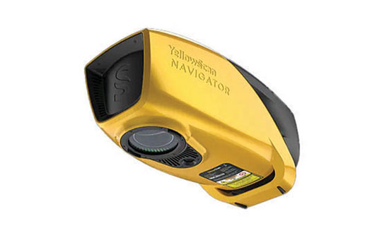
YellowScan Navigator is a bathymetric lidar system designed for surveyors to map underwater topography in rivers, ponds, and coastal areas.
The system features a laser scanner developed in-house over the course of five years and has been heavily tested to achieve optimal performance. The compact system can map waterbeds with a depth of up to 3 m and can reach a depth of 18 m in perfectly clear water conditions, according to the company. It can be flown up to 100 m above the water surface and provides measurements with an accuracy of 3 cm. Additionally, a camera is embedded for true-color data visualization.
YellowScan, yellowscan.com
3D Model Editing Software
For aerial surveying, transportation, and emergency responses
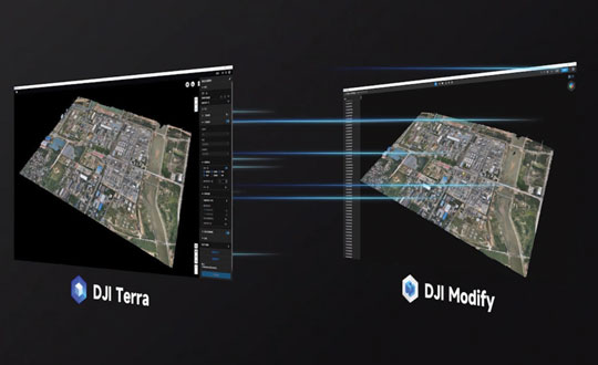
DJI Modify is an intelligent 3D model editing software. It can be seamlessly integrated with DJI’s enterprise UAVs and 3D modeling and mapping software, DJI Terra. When integrated with these products, the software can be used for aerial surveying, transportation, and emergency responses.
DJI Modify paired with DJI Terra offers users an end-to-end solution from modeling to model editing. Once DJI Modify has been enabled, DJI Terra files for model editing are automatically generated, including pre-identified objects and pre-processing of the model. It is designed to make repairing common 3D model defects seamless and efficient. As of early 2024, DJI Modify will only support repairing models built by DJI Terra.
DJI Modify allows for model files to be quickly imported and exported to the DJI Terra and other third-party software. Its intelligent auto-repair editing supports flattening, editing textures, repairing water surfaces, removing floating parts, and filling holes. Edits can be made using one-click repairs or manually by selecting custom polygons, areas or meshes.
The software’s smoother model display technology allows high- and low-quality models to be viewed and edited in a single interface. Changes made can be synchronized across both models and previewed immediately, which allows users to address model editing issues in real-time.
DJI, store.dji.com
OEM
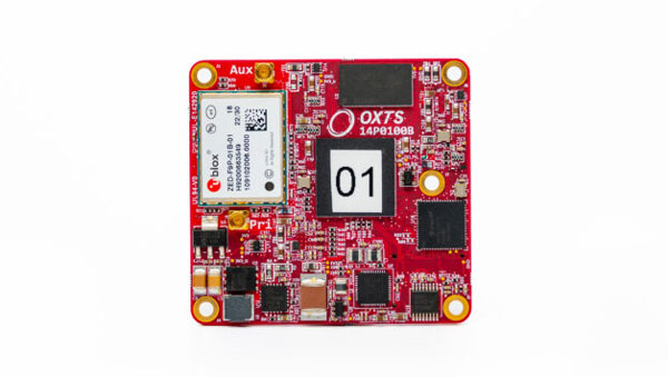
GNSS/IMU
Uninterrupted position, orientation, and dynamics
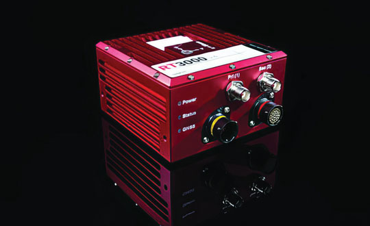
RT3000 v4 GNSS inertial measurement unit (IMU) combines two survey-grade GNSS receivers with OxTS’ IMU10 inertial technology. The RT3000 v4 offers uninterrupted position, orientation and dynamics in challenging environments.
The IMU will reach the desired specification within three minutes of low dynamic movements, which reduces the time and space required for high dynamic maneuvers before each data collection.
Users can customize the INS with optional features and software integrations to create the ideal INS for individualized projects, including lidar surveying and mapping or positioning in GNSS-denied or challenged environments.
Oxford Technical Solutions (OxTS), oxts.com
Precision Lidar Technology
Provides vision capabilities in challenging environments
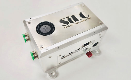
The Eyeonic Vision System Mini (Eyeonic Mini) supports sub-millimeter resolution in a reduced size. The system integrates a full multi-channel FMCW lidar on a single silicone photonic chip and an integrated FMCW lidar system-on-chip (SoC).
The Eyeonic Vision Chip combines crucial photonics functions into a coherent vision sensor. The system’s accuracy stems from a 4-channel FMCW LiDAR chip — supported by Indie Semiconductor Surya SoC technology — to provide robots with sub-millimeter depth precision from distances exceeding 10 m.
The technology offers enhanced precision and can be used in automation, including warehouse logistics and artificial intelligence (AI) machine vision applications. Palletizing robots equipped with the Eyeonic Mini can view and interact with pallets, which aims to optimize package placement and truck loading with greater efficiency and safety.
SiLC Technologies, silc.com
PNT Platform
Used in critical defense operations
The Endura Epoch Platform provides robust and resilient positioning, navigation, and timing (PNT) services critical in defense operations.
The MEMS oven-controlled oscillator (OCXO) can boost the resilience of PNT systems and other equipment, including radars, field and airborne radios, satcom terminals, and avionics against spoofing, jamming and other disruptions in GPS signals.
Based on the Epoch Platform, the Endura Epoch MEMS OCXOs are designed to meet the challenging shock and vibration conditions found in aerospace and defense. These devices are manufactured using semiconductor processes that deliver the reliability and quality expected from silicon devices. The same level of reliability cannot be achieved by quartz crystal OCXOs, specifically in extreme conditions.
The Endura Epoch MEMS OCXOs, compared to quartz crystal OCXOs, includes various features and benefits, including programmable frequencies from 10 to 220 MHz; a 20,000 g shock survivability rating; up to 20 times better frequency stability over temperature; up to three times better Allan deviation, a measure of short-term frequency stability; surface-mountable, small footprint and low height 9.0 x 7.0 x 3.6 mm; low weight of 0.35 g; 420 mW steady state power.
SiTime Corporation, sitime.com
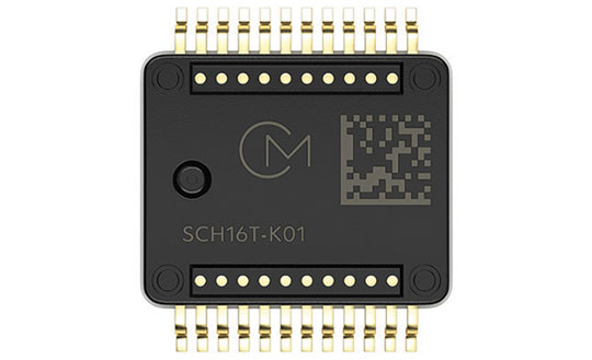
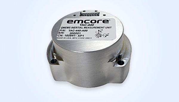
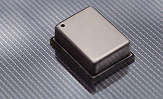
IMU
With an XYZ-axis gyroscope and accelerometer
The SCH16T-K01 is an inertial measurement unit (IMU) featuring a XYZ-axis gyroscope and a XYZ-axis accelerometer, for a total of six degrees of freedom.
The SCH16T-K01 includes a sophisticated gyro with typical bias instability of 0.5 dph and up to 0.3 mdps/√Hz noise density. The accelerometer has a dynamic range of up to 26 g, which provides resistance against saturation and vibration.
The component’s output is internally cross-axis compensated, which eliminates the need for extensive calibration. Through the integration of these features, the SCH16T-K01 can deliver accurate measurements in machine control and guidance without field calibrations.
It is suited for industrial applications such as construction and agricultural machines, material handling equipment, marine instrumentation, robotics, and UAVs.
Murata, murata.com
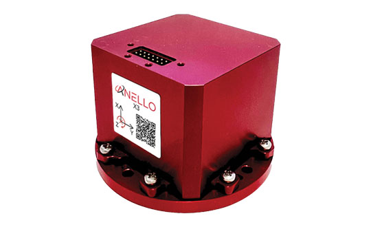
3-Axis Optical Gyroscope IMU
For GPS-denied environments
The ANELLO X3, a 3-axis optical gyroscope inertial measurement unit (IMU), is designed for GPS-denied and challenging environments.
The IMU leverages ANELLO SiPhOG (Silicon Photonics Optical Gyroscope) technology and serves as a light, low-power tri-axial optical gyroscope offering high accuracy, performance, and reliability for autonomous applications.
The ANELLO X3 can be used in a variety of applications, including autonomous commercial and defense applications involving robots, UAVs, electric vertical take-off and landing (eVTOL) aircraft and various maritime and land vehicle applications, including high-accuracy surveying and mapping.
ANELLO Photonics, anellophotonics.com
MOBILE
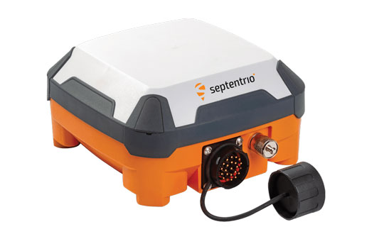
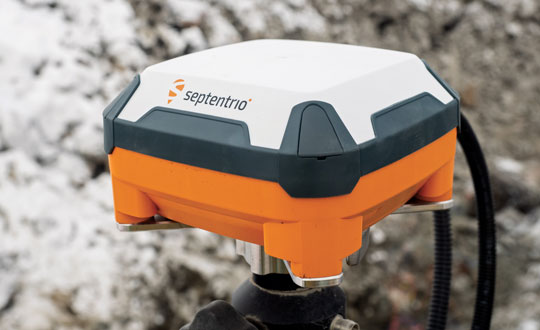
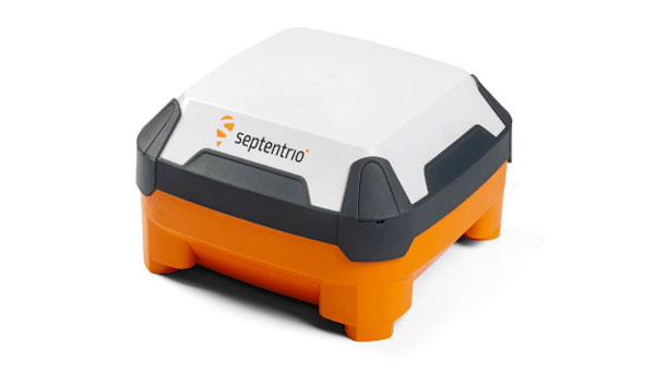
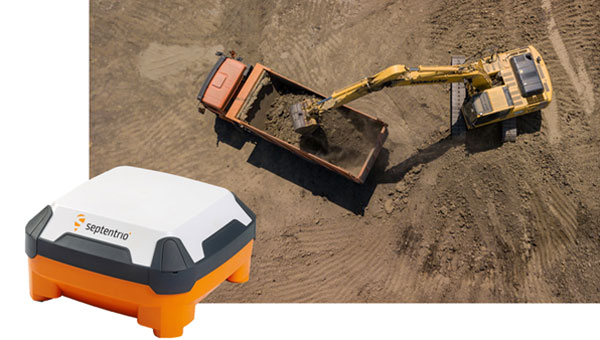
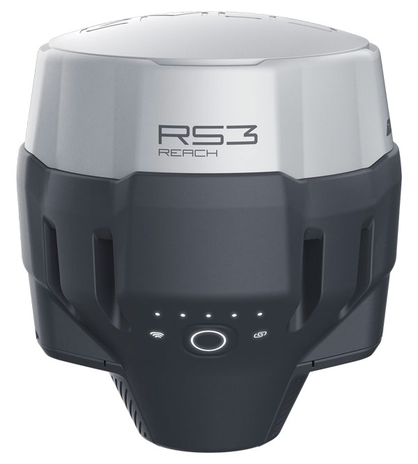
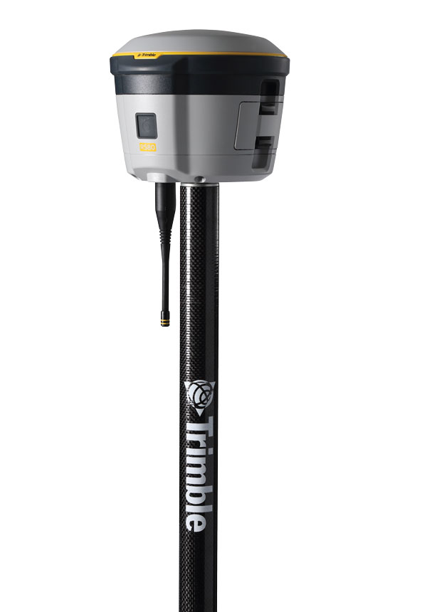
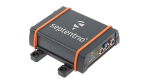
Smart Antenna
Centimeter-level RTK positioning
The AntaRx smart antenna is designed for machine automation and control in construction, precision agriculture, and logistics. It is enclosed in a rugged and compact housing for simplified installation and can handle high levels of shocks and vibrations, making it ideal for harsh industrial environments such as construction and mining.
The multi-frequency receiver offers centimeter-level real-time kinematic (RTK) positioning and can be used in inertial navigation system (INS) integration, dual antenna mode, and 4G cellular communication. It is available in several configurations, including as a GNSS smart antenna or a GNSS/INS smart antenna system and can be integrated as an inertial measurement unit (IMU).
The receiver technology integrates the company’s GNSS+ algorithms, including advanced multipath mitigation, which offers uninterrupted operation in challenging conditions such as near high structures or machinery.
Septentrio, septentrio.com
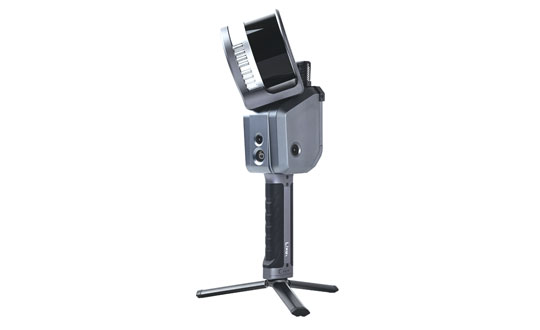
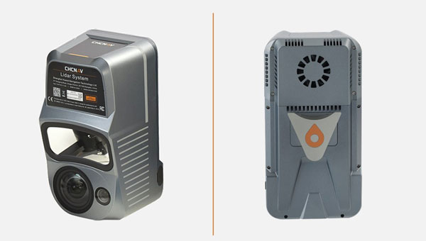
Handheld Scanner
With SLAM technology
The Lixel X1 is a powerful 3D scanner that combines lidar, visible-light and motion cameras, and high-precision inertial sensing using SatLab’s simultaneous localization and mapping (SLAM) technology.
Data and scene reconstruction can be previewed in real time and can be exported immediately after scanning without the need for post-processing, which aims to simplify workflows and enhance efficiency.
The system enables scans to be resumed from breakpoints, which allows surveys to be broken up into convenient segments. It provides up to 60 minutes of continuous operation and can be easily mounted to UAVs and other mobile mapping platforms.
SatLab Geosolutions, satlab.com
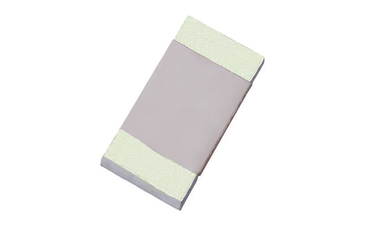
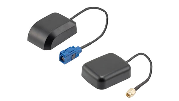
Ceramic Antenna
For connectivity on L1 GNSS signals
Admotus is a surface-mount ceramic antenna designed for connectivity on L1 GNSS signals on all constellations, including GPS-L1 at 1575.42 MHz; GLONASS L1, 1602MHz; Galileo L1, 1575.42 MHz; BeiDou (B1); and QZSS. It offers comparable performance to a small patch antenna on a small ground plane.
The ceramic antenna has an ultra-low profile measuring a mere 1.0 x 0.5 x 0.5 mm, requires 7 x 15 mm clearance area and offers improved performance on small PCB sizes.
Admotus offers a peak gain of 0.9 dBi with an average gain of –2.6 dB and offers maximum return loss of –11.5 dB and a maximum VSWR of 1.8:1. A companion evaluation PCB is also available for internal analysis.
It is suitable for all GNSS positioning applications in the L1 band (1559 – 1609 MHz) such as wearable devices for fitness and medical monitoring, small portable tracking devices used to track keys, pets, bikes, UAVs, agricultural robotics, and telematics devices.
Antenova, antenova.com
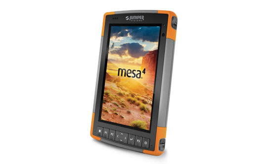
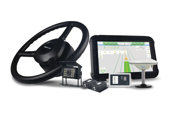
Rugged Tablet
For mobile field workers
The Mesa 4 Rugged Tablet features a 7-inch display and runs on Windows 11. It is designed to provide powerful rugged computing and data collection to mobile field workers.
The Mesa 4 comes with a new Intel N200 processor. It offers up to three times the CPU performance of the Mesa 3 and has an increased RAM size and speed to enhance its processing power. Mesa 4 has an IP68 rating, MIL-STD-810H certification and ergonomic design for all-day carrying.
Juniper Systems, junipersys.com
UAV
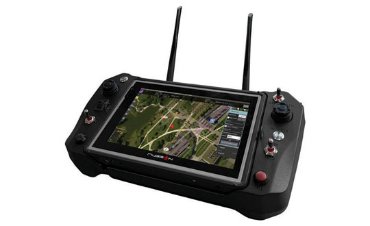
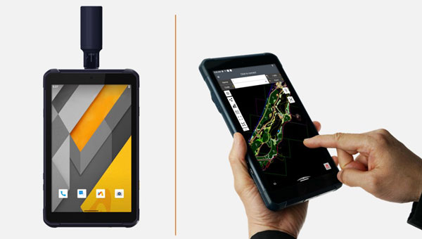
UAV Ground Control System
On an 8-inch rugged tablet
The Ground Control System (GCS) for UAVs is centered around RuggON’s LUNA 3 8-inch rugged tablet. It is designed to provide real-time control, telemetry, and satellite positioning for connected UAVs.
GCS is designed to provide users more control over a variety of UAVs by using the LUNA 3 rugged tablet, which has a large and high-definition screen to provide video feedback during operations. The system is also certified to provide GNSS positioning and tracking services.
Featuring a low-latency video software decoder, GCS allows for real-time high-resolution video viewing and data collection. Engineered to withstand dust, shock, and water, the control system can withstand challenging environments.
The LUNA 3 8-inch rugged tablet stands as a powerful and efficient model within its class, powered by an Intel Core i5 processor (1145G7E) with Intel Iris Xe graphics and the Windows operating system. Its sunlight-readable display supports night and stealth modes, which is cruicial for law enforcement and military applications. The tablet offers touchscreen functionality for enhanced operator convenience, complemented by ethernet and optional Wi-Fi 6, and 4G LTE connectivity.
RuggON, rugon.com
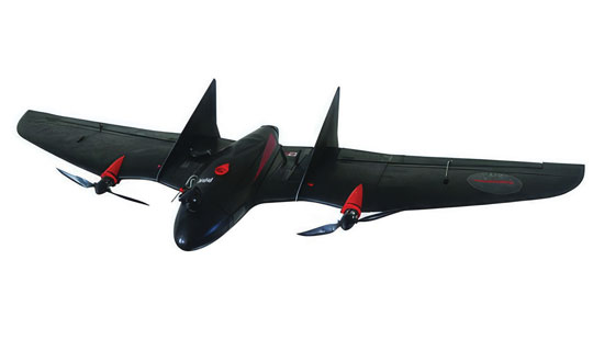
VTOSL
Bridging the gap between land and sea
The VT-Naut, vertical takeoff and short landing (VTOSL) is a versatile aerial solution designed for a variety of applications, including high-precision mapping and surveying for inspection, scouting, observation, and agriculture.
The VT-Naut can land on water, which makes it ideal for shipboard or coastal operations, and opens new ways for users to collect and observe data. It has a long-range telemetry link of 30 km and a flight endurance of up to 90 minutes. Its compact and robust body design provides durability and resilience in harsh environments.
The VT-Naut UAV system offers a cost-effective alternative to full VTOL platforms, particularly for users who require extensive surveying capabilities and have some flexibility in landing site selection. The system eliminates the extra costs associated with acquiring and operating a VTOL multirotor drone.
Aeromao, aeromao.com
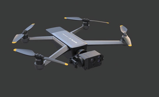
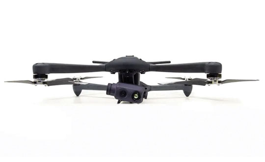
Folding UAV
For challenging environments
The AIDrone UAV is designed for a variety of applications, from infrastructure inspections and renewables to defense and public safety.
The UAV features a high-performance payload, fitted with a 64MP EO/IR camera mounted on a dual-axis gimbal that can support vertical rotation of up to 200°. AIDrone can spot millimeter-sized cracks and detect subtle temperature changes in challenging environments.
AIDrone uses Nearthlab’s vision-based autonomous flight technology to operate autonomously — in zero-light and GPS-denied environments — both indoors and outdoors.
It weighs around 4 lbs and has a foldable structure. AIDrone is designed for intelligence, surveillance, and reconnaissance (ISR) purposes, which makes it ideal for crisis management scenarios such as wildfire response and law enforcement.
Nearthlab, nearthlab.com
ISR UAV
With jamming resistant-radio
The Ghost Dragon intelligence, surveillance, and reconnaissance (ISR) UAV offers higher resistance against jamming and spoofing. The UAV is equipped with a thermal and visual light camera and jamming-resistant radio. Its wide frequency hopping radio is used to provide a jamming-resistant video and telemetry link, which makes it difficult to detect the UAV and interfere with the mission.
The Ghost Dragon ISR uses a dual-band GNSS module that operates on both L1 and L5 bands, which allows for flight operations even in challenging environments. The UAV can operate in radio silence mode in the presence of GNSS and store reconnaissance data on an encrypted SD card to view after the UAV has landed. The video and target location information streamed to the operator is also georeferenced.
The UAV can be redirected, flown back to base, or handed to another operator at a different ground control station at any time.
Krattworks, krattworks.com