Category: Applications

  • FGCS meets to address the National Spatial Reference System

    FGCS meets to address the National Spatial Reference System

    In last month’s GPS World newsletter, I mentioned that the National Geodetic Survey (NGS) would host a meeting of federal geospatial agencies under the auspices of the Federal Geodetic Control Subcommittee (FGCS). The purpose is to increase awareness and coordinate the NSRS Modernization across the government.

    The FGCS meeting took place on Wednesday, Jan. 21, 2026. This session was highly informative and played a key role in aligning federal agency engagement strategies and self-assessments in preparation for the final adoption of the modernized NSRS and its associated new datums.

    The FGCS holds a central position within the Federal Geographic Data Committee (FGDC). It coordinates geodetic activities across the federal government by

    • Developing and promoting standards
    • Advancing the use of authoritative geodetic control
    • Facilitating the modernization of the NSRS across agencies
    • Recommending the official adoption of the modernized NSRS by the FGDC as the foundational basis for geodetic control throughout the United States.

    The agenda for the Jan. 21 meeting is detailed in the section titled “Federal Geodetic Control Subcommittee Meeting.” This gathering supported broader efforts to raise awareness, ensure coordination and prepare agencies for the upcoming transition to the modernized NSRS, with formal approval and release anticipated later in 2027.

    Federal Geodetic Control Subcommittee Meeting

    January 21, 2026

    Agenda: 

    MC: Christine Gallagher

    TimeTopicPresenter
    1:00 – 1:15 pmWelcome and IntroductionsDaniel Roman
    1:15 – 1:20 pmNational Geodetic Survey (NGS) UpdateMarian Westley
    1:20 – 1:30 pmGeodetic Control Theme Update and its Modernization TimelinesDaniel Roman
    1:30 – 2:00 pm NGS Modernization Engagement Plan and ProgressDana J Caccamise II / Christine Gallagher
    2:00 – 2:15 pmBureau of Ocean Energy Management / Kearns & WestAndy Archer / Kyle Vint
    2:15 – 2:30 pmUS Census National Spatial Reference System (NSRS) Modernization PreparationVince Ossier / Josh Coutts
    2:30 – 2:40 pmBreak
    2:40 – 2:55 pmUS Department of Transportation NSRS Modernization PreparationAmy Nelson / Derald Dudley
    2:55 – 3:10 pmAmerican Society for Photogrammetry and Remote Sensing & National Society of Professional Surveyors Working Groups Chris Parrish / Linda Foster
    3:10- 3:50 pmDiscussion: Q&A from Agency presentations. What hurdles to implementation do you see or anticipate? Share your insights from internal working groupsGroup Discussion Moderator:  Dana J Caccamise II and Daniel Roman
    3:50 – 4:00 pmClosing Remarks Daniel Roman
    Adjourn to Silver Branch

    The meeting lasted three hours and covered a lot of material. Below are highlights; contact FGCS for the full meeting recording.

    Christine Gallagher, NGS, opened the FGCS session and introduced Dan Roman, NOAA’s National Geodetic Survey senior advisor for geodesy.

    Roman welcomed everyone and briefly outlined the meeting’s purpose. He then introduced Marian Westley, director of the Center for Operational Oceanographic Products and Services (CO-OPS) and current acting director of NGS.

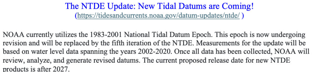
    Westley’s remarks were brief but important. She noted CO-OPS manages tide gauges and is updating several datums in partnership with NGS, including the Great Lakes International Great Lakes datum. She said the United States and Canada, along with NOS and other federal agencies such as the Corps of Engineers, are heavily involved in Great Lakes management. She also reported that CO-OPS is updating the National Tidal Datum Epoch (current NTDE: 1983-2001) and is working closely with NGS to tie the updated NTDE to the new NSRS. See the image titled “The NTDE Update: New Tidal Datums are Coming!

    During Roman’s comments, he highlighted the agencies and professional societies participating in the meeting presentations and provided an update on the latest rollout schedule for the modernized NSRS.

    He emphasized that this Jan. 21, FGCS meeting marks the start of a broader coordination process. The primary purpose of this high-level session was to facilitate the sharing of experiences, strategies, and best practices among federal agencies as they prepare for NGS’s NSRS modernization and the transition to the new reference frames and datums.

    Roman noted that future FGCS meetings will shift to a more technical and detailed focus. These subsequent sessions will allow agencies to present their self-assessment results, outline implementation strategies, and discuss progress toward adopting the modernized NSRS.

    Key objectives across these meetings include:

    • Collecting questions and feedback from participants,
    • Understanding user needs and required accuracy levels,
    • Identifying anticipated challenges during the transition,
    • Exploring opportunities for federal agencies to collaborate and support one another throughout the implementation process.

    This series of FGCS engagements aims to ensure coordinated, informed, and effective preparation across the federal government ahead of the final adoption and full rollout of the modernized NSRS.

    Here are a few key points based on Dan’s remarks:

    • Today’s presentations provide a broad overview of geospatial data modernization to inform departments about actions they may need to take and to start a dialogue about what each department is doing.
    • NGS encourages agencies to form working groups; those groups must define their own requirements and create migration plans, including assessing existing data, required accuracies, and the tools needed based on product accuracy statements.  [Note: My October 2025 GPS World newsletter highlighted organizations that are forming 2022 Reference Working Groups.]  NGS will designate points of contact to facilitate discussions and planning.
    • FGCS provides guidance on using geodetic data with various tools, models, and SOPs. User needs vary by accuracy: e.g., a 3-meter horizontal allowance (aids to navigation) is straightforward, while 3-centimeter requirements (e.g., FEMA Elevation Certificate) need more precise methods.
    • Several beta products released in July 2025 are being finalized, enabling the private sector to integrate them into services.  NGS is currently developing models and software to transform coordinates from the old datum to the new one. These models are expected around March, and in June/July NGS anticipates releasing an updated Beta NCAT tool to transform coordinates to the new datum. This tool will help users understand differences in local datums.
    • Final steps include FGCS recommendations for FGDC to adopt the new NSRS and to publish a Federal Register notice on the adoption of the modernized NSRS, anticipated to be completed in early 2027.

    After Dan Roman’s comments, Dana J Caccamise II gave a presentation describing NGS Modernization Engagement Plan and Progress.  Dana should get an award for material he has prepared and for his work to assist agencies and professional organizations in preparing for the new NSRS.  In my October 2025 GPS World Survey Scene newsletter, I highlighted the work of Dana J. Caccamise II, NGS regional geodetic advisor. Dana has developed vital guidance materials shared with federal agencies — such as the Federal Geographic Data Committee (FGDC) and professional organizations including the National Society of Surveyors (NSPS)American Society of Photogrammetry and Remote Sensing (ASPRS), and American Association for Geodetic Surveying (AAGS)

    Here are a few key points based on Dana’s presentation titled “Visualizing Impact: Preparing for NSRS Modernization Through Geospatial Readiness and Collaboration.”

    • Caccamise said that what started as a focused task quickly grew into a broader strategic effort. He shared insights to encourage thinking about NSRS modernization not merely as a technical update but as a strategic business decision that will shape how agencies create, manage, and share basic data across programs, systems, and partnerships.
    • Caccamise briefly provided details to the U.S. Census. Before diving into modernization, he offered a personal glimpse of what it’s like to do a federal detail across agencies, noting he was fortunate to do a detail with the Census not long ago.
    Image: FGCS January 21, 2026, Public Meeting
    Image: FGCS Jan. 21, 2026, Public Meeting
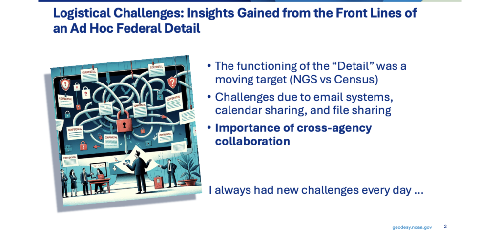
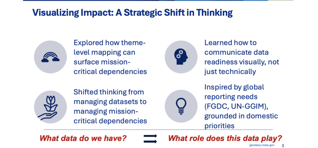
    • Drawing on his experience, Caccamise emphasized the importance of cross-agency readiness and of building resilient trust and communication structures. While on detail at the Census, he was regularly surprised by new challenges, which made the work engaging; he strongly recommended that others take a detail at another agency if they have the opportunity. A key takeaway was the value of visualizing impact: beyond cataloging geospatial datasets, users must identify which support critical decisions, which are shared across agencies, and which risk becoming outdated if you don’t adapt. Mapping themes and workflows revealed real dependencies and, more importantly, vulnerabilities. That detail shifted his  focus from “what data do we have” to “what roles does this data play.”
    Image: FGCS January 21, 2026, Public Meeting
    Image: FGCS Jan. 21, 2026, Public Meeting
    • Efforts around NSRS modernization include a key product developed by Caccamise: the Ready Package. Designed to help agencies assess their readiness for NSRS modernization, the package includes communication tools, technical checklists, and talking points to support agency staff.
    Image: FGCS January 21, 2026, Public Meeting
    Image: FGCS Jan. 21, 2026, Public Meeting
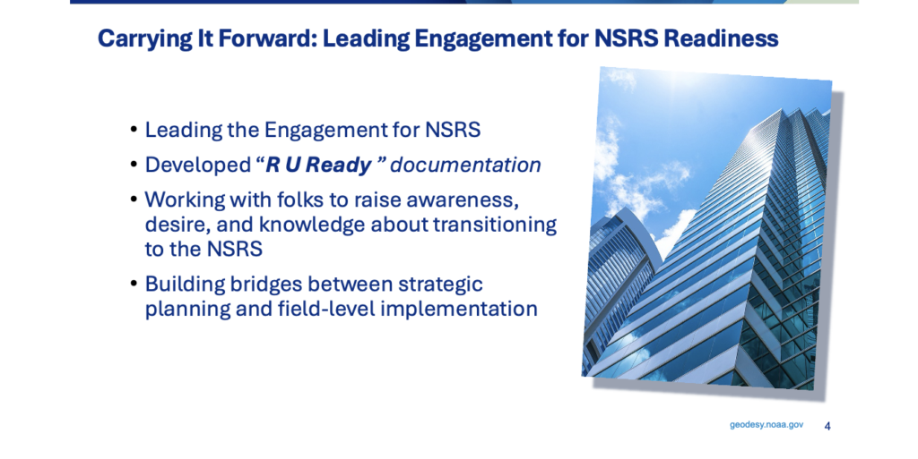
    • He mentioned that from field-level GIS technicians to senior policy leads, everyone needs to understand what’s changing and why it matters. A key part of engagement is meeting people where they are. Dana has worked with agency partners to raise awareness, build interest, and strengthen understanding — not just of technical changes but of the organizational shifts needed for a smooth transition.
    • For agencies whose statistical workflows depend on spatially referenced data, that means ensuring location-based datasets remain accurate, comparable over time, and interoperable across programs when the reference system changes. Ultimately, this is about more than new coordinates: it’s about linking strategic planning to operational implementation, from data collection and integration to interagency coordination and informed decision-making.
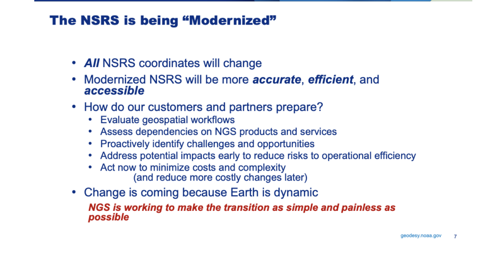
    • He mentioned that the big question he’s hearing from many organizations is: how should customers and partners prepare for modernization?   He provided the following advice.  Start by evaluating your geospatial workflows to understand how the transition will affect data management, operations, and decision-making. Assess dependencies on NGS products and services to ensure continued access and interoperability and proactively identify challenges and opportunities – he mentioned that NGS can’t do this for you because each agency’s situation is unique. Address potential impacts early to reduce operational risk by finding weak points before they cause surprises. Act now: preparing early will minimize future cost and complexity.
    Image: FGCS January 21, 2026, Public Meeting
    Image: FGCS Jan. 21, 2026, Public Meeting
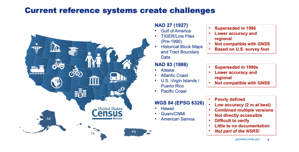
    • For example, working with the Census under the current national spatial reference system highlights the geographic scope of some operational areas, which span multiple tectonic plates as modeled in the modernized NSRS. Even small regional differences can affect how location-based data are collected, integrated, and compared — especially for programs that need consistent, long-term geospatial baselines. Today, federal agencies commonly use three reference systems — NAD27, NAD83, and WGS84, which complicates geospatial data management.
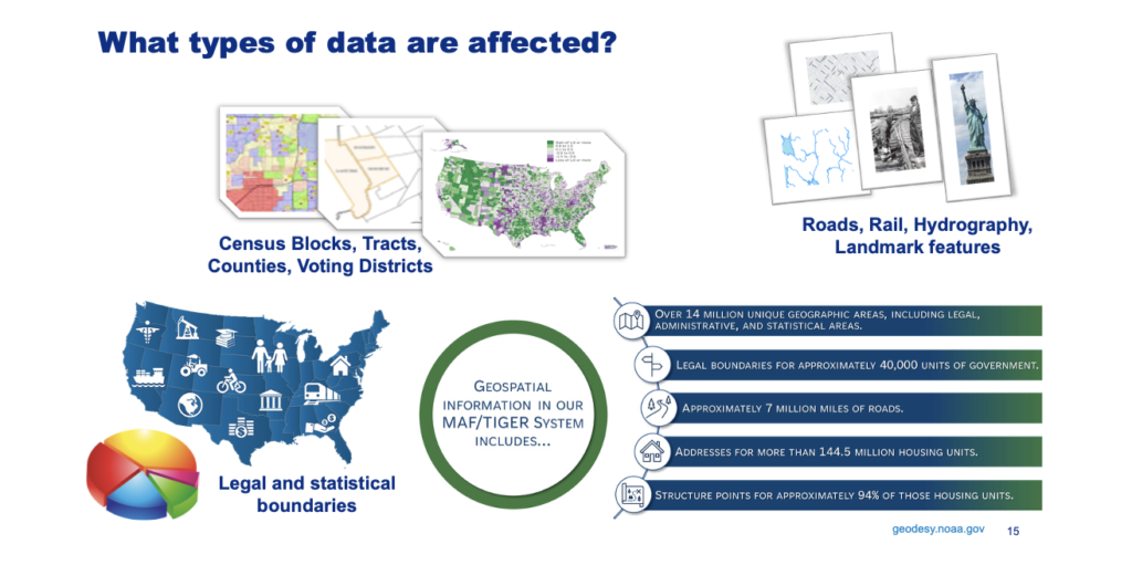
    • The Census is a major user and producer of geospatial data, relying on GIS to support operations. This includes the MAF/TIGER geographic database, which contains roads, rail lines, hydrography, landmark features, and legal and statistical boundaries.
    • Along with many other critical datasets, the Census’s collaborative spatial and statistical research is more effective and interoperable when grounded in a common reference system, such as the National Spatial Reference System.
    Image: FGCS January 21, 2026, Public Meeting
    Image: FGCS Jan. 21, 2026, Public Meeting
    • Because these datasets are inherently geospatial, many, especially those requiring high positional accuracy or relying on external references such as airborne or satellite data, will be affected by NSRS modernization. The update will enable more consistent data stewardship and support integrated spatial analytics, helping align with individual agency spatial data strategies. Bureau-level geospatial work becomes more effective and future-ready when supported by a modern, shared spatial reference system like the NSRS.
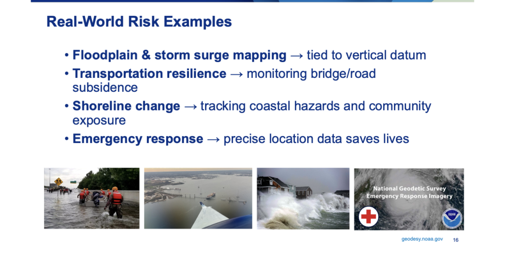
    • One of the biggest risks is cultural, not technical. If the NSRS is treated as just another dataset, rather than an enabling framework, the foundation for other systems weakens. When the NSRS is recognized as the framework, everything built on it has a solid base. You can’t manage risk if you can’t measure it—and the NSRS is how we measure. Here are a few practical examples.
    • Floodplain mapping and storm surge models depend on accurate vertical data. Errors of even a foot can leave neighborhoods unprotected or cause unnecessary regulation.
    • In transportation, subsidence is a hidden risk: roads and bridges may seem fine until precise geometric monitoring reveals sinking.
    • Shoreline change is a growing challenge; coastal communities need accurate shoreline monitoring for planning and insurance.
    • In public safety, emergency response relies on precise locations — from 911 calls to field deployments. Seconds and meters matter when lives are on the line.
    Image: FGCS January 21, 2026, Public Meeting
    Image: FGCS Jan. 21, 2026, Public Meeting
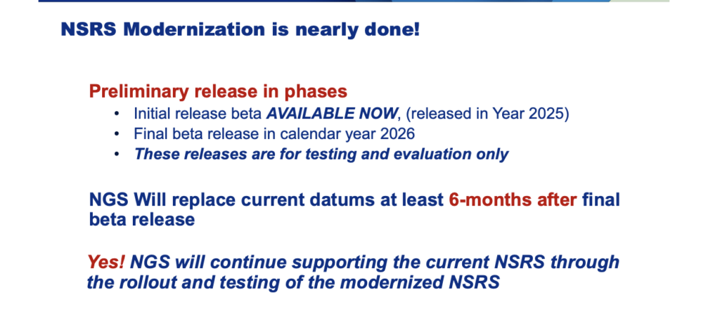
    • As Roman mentioned, Caccamise also stated that the modernized NSRS is being released in phases. Initial beta releases are available now for testing and evaluation—not final production. NGS plans to release the remaining components in beta during this calendar year. The modernized NSRS will replace the current datums at least six months after the final preliminary component is released, giving partners time to review the beta and provide feedback. Near the end of this period, FGCS will convene to discuss and socialize the modernization details and the planned datum replacement.

    Next steps for your agency’s modernization:

    • Evaluate operational needs and identify changes that aren’t necessary.
    • Assess organizational impacts and staff readiness—are teams prepared for modernization?
    • Determine how existing programs and regional support will be affected.
    • Collaborate with partner agencies to align shared datasets, reduce redundancy, and maximize efficiency.
    • Prioritize leadership and communication to ensure the organization understands the changes.
    • Plan for future improvements in spatial accuracy, even if you don’t need them immediately.
    Image: FGCS January 21, 2026, Public Meeting
    Image: FGCS Jan. 21, 2026, Public Meeting
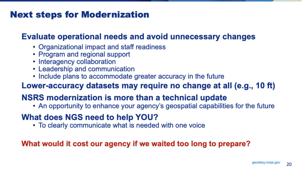
    • As noted by Dan Roman, Dana Caccamise also highlighted that many lower-accuracy datasets may not require coordinate changes beyond updating their metadata—typically those with spatial accuracy on the order of 10 ft or worse. However, he also noted an important caveat: many operational workflows don’t actively read or enforce metadata. In those cases, the risk is not the dataset itself but the accuracy context that becomes embedded as data moves through systems.
    • An early, critical step is therefore to identify not only which datasets are likely unaffected but also how those datasets are consumed, transformed, and reused. That approach prevents unnecessary work and avoids unintended downstream impacts. Remember: NSRS modernization is more than a technical update, it’s an opportunity to strengthen your agency’s future geospatial capabilities.
    • Now, I know this newsletter is long, but I would like to highlight one more presentation that I believe provides a model for other agencies to follow.  That is, the presentation of the Department of Interior’s Bureau of Ocean Energy Management (BOEM) activities presented by Kyle Vint (Vice President, Kearns & West) – “From Proactive Engagement to Lasting Impact: BOEM’s Path to Datum Readiness.” 
    Image: FGCS January 21, 2026, Public Meeting
    Image: FGCS Jan. 21, 2026, Public Meeting

    Kearns & West is a communications and engagement specialization firm.  The materials that they develop to support internal communications and outreach within an organization are available for other organizations. They provided a QR code for others to access their resources.

    Vint outlined BOEM’s operating context and described how the agency is proactively addressing NSRS modernization, including several strategies.

    Image: FGCS January 21, 2026, Meeting
    Image: FGCS Jan. 21, 2026, Meeting

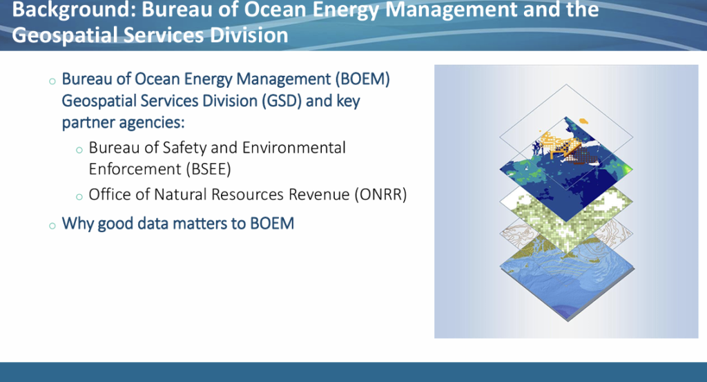
    BOEM’s challenges are partly historical: until about 2010, it was part of a parent agency that has since split into three separate agencies. That fragmentation means BOEM must coordinate data and change management not only internally but across three agencies that share data centers and geospatial datasets. BOEM relies on authoritative geospatial data to manage offshore energy and mineral activities on the Outer Continental Shelf; BOEM’s Geospatial Services Division supports this by maintaining leases and boundaries that underpin program decision-making. Because the ocean serves many purposes, BOEM relies on multiple layers of information from different agencies to support those decisions.

    BOEM’s path to modernization is further complicated by internal organizational factors. The agency struggled with the NAD27-to-NAD83 transition due to resource constraints and misunderstandings — some staff believed modernization would alter legal lease blocks, which they expected to be immutable — so the transition was not fully implemented.

    Image: FGCS January 21, 2026, Meeting
    Image: FGCS January 21, 2026, Meeting

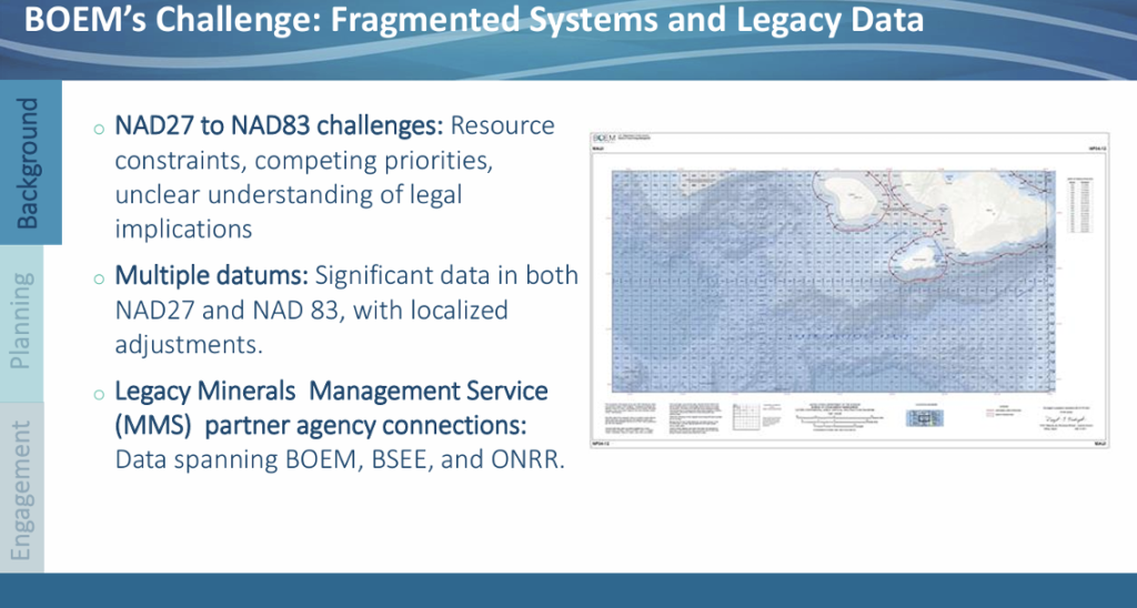
    BOEM holds large datasets in both NAD27 and NAD83, fragmenting its workflow. Maintaining and converting between multiple reference systems is labor-intensive and introduces inconsistencies.

    BOEM must dedicate substantial staff time to managing data in multiple reference systems. BOEM’s Geospatial Services Division recognized early that continuing workarounds would increase risk over time, so they began proactive modernization planning.

    The Geospatial Services Division saw this as more than a technical issue — it’s also a people, communication, and resourcing challenge. BOEM shifted from fragmented efforts to a proactive, multi‑year planning approach emphasizing governance, leadership buy‑in, and clear communication. The Geospatial Services Division established a milestone‑based approach for consistent messaging and coordination across stakeholders and offers internal expertise to support programs and regions as they assess costs and technical complexity.

    Their strategy seeks common ground to pool resources for shared problems and to use the Geospatial Services Division as an internal augmentation so individual offices aren’t forced to opt out. This reduces cost uncertainty and enables realistic planning for timelines and required participants.

    Image: FGCS January 21, 2026, Public Meeting
    Image: FGCS January 21, 2026, Public Meeting

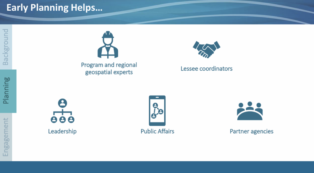
    As part of the process, user personas were created to identify who would struggle with each step and who would benefit from early, sustained engagement. For each group, they defined the value of participating and explained why they were invited.

    BOEM leaderships were treated like investors—they ensured they brought geospatial experts to meetings so questions could be answered, and so leadership had actionable budget information for long‑term planning. At the program and regional level, data experts who know existing datasets, reference systems, dependent applications, and potential workflow challenges were part of the process.

    They also documented internal roles so others can model the approach. The Geospatial Services Division coordinates the effort across the organization. Program and regional experts provide domain knowledge. Kearns & West (technical and communications contractors) supported messaging, prepared materials, and ran meetings so BOEM staff could focus on the conversation. Clear roles and sustained engagement have been critical in this multi‑year planning effort.

    Image: FGCS January 21, 2026, Public Meeting
    Image: FGCS January 21, 2026, Public Meeting

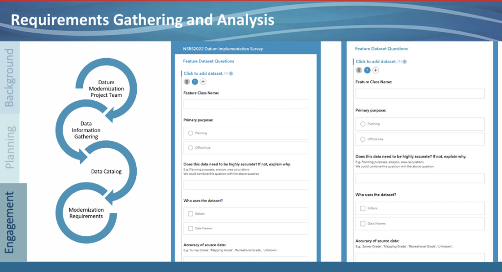
    The team developed a Survey and sent it to each program and region to gather resource requirements. The survey asked what data they have and its characteristics, which applications or workflows depend on that data and could be affected by modernization, and what technical resources they expect will be needed to support budgeting.

    Image: FGCS January 21, 2026, Meeting
    Image: FGCS January 21, 2026, Meeting

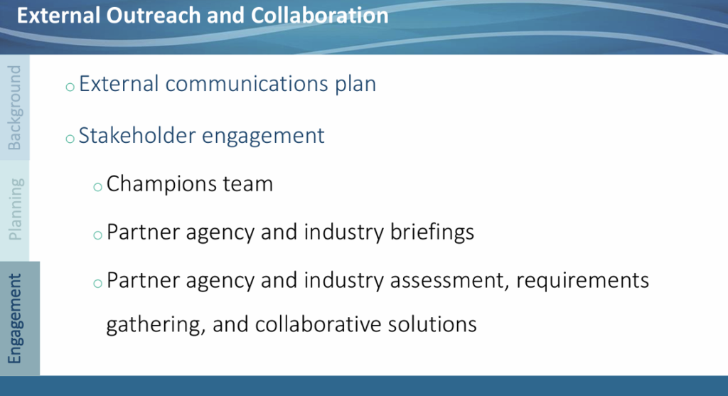
    As part of the process, they are building internal champions to advocate for the effort, simplifying complex issues so staff can brief leadership, and convening agencies, partners, and industry to co-create solutions.

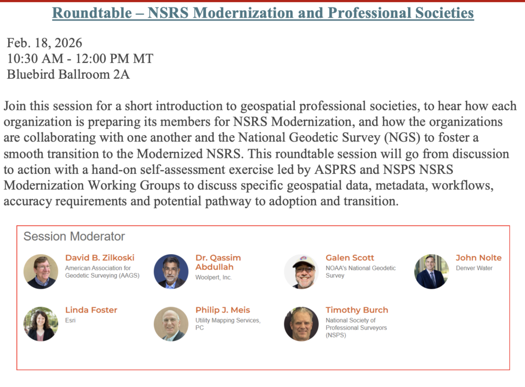
    Finally — thanks for sticking with this lengthy newsletter. I know it’s long, but the information is important for federal agencies and their contractors. One more item: a key session is scheduled for GeoWeek — “Roundtable – NSRS Modernization and Professional Societies” — on 02/18/2026 at 10:30 AM. See the box titled “Roundtable – NSRS Modernization and Professional Societies” for presentation and speaker details.

  • RIN report: How GNSS interference harms maritime safety

    RIN report: How GNSS interference harms maritime safety

    The UK Royal Institute of Navigation has released a special report on GNSS-interference and its impact on the maritime sector.

    Impacts of GNSS Interference on Maritime Safety is a special report by the RIN Maritime GNSS Interference Working Group on the impacts of GNSS Interference. Survey data was compiled from more than 100 sector experts and 300 vessel captains, supported by interviews with dozens of people involved in the operations and supply chain of vessels that regularly encounter GNSS interference.

    GNSS interference refers to anything that disrupts a ship’s satellite-based positioning signals, usually caused by jamming and spoofing.

    In 2025, at least two collisions and groundings were reported in mainstream media linked to GNSS interference in regions such as the Baltics, Straits of Hormuz and the Red Sea. With hundreds of vessels being affected daily, the RIN report details for the first time the scale of the problem on modern digital vessels, where GNSS jamming and spoofing present a significant cybersecurity vulnerability and urgent risks to maritime safety.

    Survey data exposes the vulnerability of critically important systems such as Global Maritime Distress and Safety Systems (GMDSS) and other SOLAS-mandated equipment that rely on satellite positioning and timing. 

    “The report has highlighted serious safety concerns and has underlined the fact that these issues are rooted in significant cybersecurity vulnerabilities, and are not just disruptions to navigation,” said Ramsey Faragher, director of the RIN. 

    Operating within regions of known GNSS interference carries serious safety-of-life and liability implications, as key systems are expected to fail or malfunction with high probability in these conditions. The report also highlights unnecessary dependencies between GNSS receivers and a range of onboard electronics — including radar, radios (VHF/MF/HF), Navtex, speed logs, ship clocks and satellite communications — many of which do not require GNSS data for their primary function, creating avoidable points of failure and compounding operational risk.

    “The issue of GNSS interference must be taken seriously. It cannot be overcome by traditional navigation techniques when GNSS receivers are ‘baked in’ to modern ships’ critical systems, including safety systems,” said Ivana-Maria Carrioni-Burnett, maritime captain and chair of the RIN Maritime Navigation Group. “These are no longer isolated incidents and pose a real risk to life: people, property and the environment. We must do more to safeguard our seas today and the shipping of tomorrow.”

    “Despite measures to improve resistance to jamming, spoofing and other harassment measures, the threat is real and growing,” said Retired Commodore James Taylor OBE and fellow of the RIN advises. “And this threat is not only to positioning and navigation; it is to every part of every transport and navigation means and to every part of national infrastructure where timing is derived from space-based timing signals.”

    The Royal Institute of Navigation will continue to work with report partners (GLA, IALA, Nautical Institute and others) and regulatory bodies to provide expert guidance to mitigate these issues, and to establish industry-wide adoption of solutions to this problem. RIN thanks National PNT Office for its support.

    Download the report for free.

  • TDK launches STRIDE, a low-power, real-time positioning software for wearables and IoT 

    TDK launches STRIDE, a low-power, real-time positioning software for wearables and IoT 

    TDK Corporation has announced Trusted Positioning STRIDE, an embedded pedestrian dead reckoning (PDR) software solution engineered specifically for wearables such as smart watches, head-mounted devices, glasses and compact sensors.

    As OEMs push for more intelligent, context-aware wearable experiences, STRIDE provides reliable positioning without the power and hardware demands traditionally required for GNSS-based tracking. 

    Wearables today face a critical challenge: adding high-quality positioning typically requires bulky antennas, high-drain GNSS or costly custom hardware — barriers that limit form factor, battery life, and user experience. 

    STRIDE overcomes these constraints with a low-power, sensor-agnostic software engine that fuses inertial data with GNSS and opportunistic wireless signals, delivering continuous location tracking indoors, outdoors and everywhere in between. 

    STRIDE runs as embedded software, giving OEMs freedom to deploy positioning without redesigning hardware or relying on cloud connectivity. STRIDE processes sensor data in real time, ensures low latency, and can be configured for on-device, companion-device, or cloud-assisted architectures. This flexibility helps manufacturers balance performance, power, and form-factor constraints based on their device strategy. 

    For integration questions or technical documentation, contact TDK.

  • Cleared for the dirt: How robotic rovers are revolutionizing military runway assessment

    Cleared for the dirt: How robotic rovers are revolutionizing military runway assessment

    Tactical air-lifters such as the Airbus A400M, Lockheed C-130 and Boeing C-17 require precise runway roughness assessments to operate safely on unpaved surfaces. An autonomous rover system developed at the Royal Military Academy of Belgium uses RTK/PPK GNSS positioning and sensor fusion to deliver centimeter-level height measurements, drastically reducing survey time. The system provides a practical solution for rapid runway certification across military operations and humanitarian response missions.

    Unpaved runway assessment

    The Airbus A400M Atlas, the Lockheed C-130 Hercules and the Boeing C-17 Globemaster III routinely operate from unpaved runways in harsh environments far from established infrastructure. Before these aircraft can safely land, flight crews require accurate runway roughness data to assess whether the surface meets operational limits. This assessment relies on precise, quantitative measurements of the runway’s surface characteristics — a task that traditionally requires specialized survey teams and hours of manual work with GNSS equipment, resources that are often unavailable in high-tempo tactical or emergency response scenarios.

    The challenge is particularly acute because different aircraft have specific roughness tolerances. The A400M uses an equivalent bump height (EBH) methodology, while Boeing employs its Boeing Bump Criteria. The EBH requires vertical measurement precision of ±1 cm over wavelengths ranging from 5 to 100 meters. Meeting these stringent requirements with rapid, field-deployable methods has remained an operational gap — until now.

    At the Royal Military Academy (RMA) of Belgium, we developed a novel solution to this critical challenge. Our system features a rugged, autonomous unmanned ground vehicle that can rapidly perform a centimeter-accurate runway assessment with minimal user intervention. It represents a fusion of robotics, geodesy, and advanced GNSS techniques, designed specifically for ease of use by military teams in the field. The system is called Belgian Navigational Surface Inspector (BENSI).

    FIGURE 1 shows the BENSI system during a mission at a tactical landing zone with the A400Min the background. FIGURE 2 shows the BENSI system being configured by the operator during a landing preparation.

    Figure 1 The autonomous UGV (BENSI) during a mission at a tactical landing zone with the A400M Atlas in the background.
    Figure 1 The autonomous UGV (BENSI) during a mission at a tactical landing zone with the A400M Atlas in the background.
    Figure 2 The BENSI system being configured by the operator 
during the beach landing preparation at Rømø, Denmark.
    Figure 2 The BENSI system being configured by the operator
    during the beach landing preparation at Rømø, Denmark.

    This article details the system’s architecture, the integration of multiple technologies that enable the stringent precision required achieved by GNSS and sensor fusion, self-driving capabilities and its successful deployment in demanding field tests. We present a military graded solution for ensuring tactical airlift safety, enabled by modern, accessible GNSS technology and robotics.

    Quantifying runway roughness

    Deployable Air Traffic Management (DATM) and Pathfinders are responsible for ensuring the safety of aircraft operations on unpaved runways. They are tasked with assessing the quality of the runway and the Runway Safety Area (RSA) to ensure that the aircraft can land safely. The pilots analyze their assessment and take the final decision to land.

    FIGURE 3 is an example of a landing zone having an unpaved runway that needs to be evaluated for landing. FIGURE 4 overviews the landing zone by mapping and indicating features of the runway that need to be considered by the pilots. An important aspect of the DATM’s assessment is the runway’s roughness, which is quantified by the EBH.

    Figure 3  An example of a tactical landing zone.
    Figure 3 An example of a tactical landing zone.

    For modern military transport aircraft operations, runway roughness assessment is a critical safety parameter. Both major manufacturers — Airbus with its EBH methodology and Boeing with its Boeing Bump Criteria — have developed sophisticated approaches to characterize runway longitudinal roughness profiles. These methods analyze height variations over wavelengths ranging from 5 to 100 meters, requiring vertical measurement precision of ±1 cm. This rigorous assessment is essential to reduce aircraft structural fatigue, minimize maintenance costs, prevent exceedance of design limit loads, and ultimately ensure safe operations. For the A400M specifically, Airbus requires EBH characterization to determine operational limitations of the aircraft’s maximum payload.

    Figure 4  A typical mapping of a landing zone showing a 
condensed overview of DATM’s assessment.
    Figure 4 A typical mapping of a landing zone showing a
    condensed overview of DATM’s assessment.

    Traditionally, achieving this precision would involve a painstaking survey conducted by specialists using a GNSS survey system mounted on a trolley requiring human guidance along the measurement tracks totaling more than 3 km of length. For military units like the DATM and Pathfinder teams, who often are the first on the ground, this is impractical. They need a system that is rapid, reliable, simple to operate without a surveying background, and robust enough for field conditions.

    A GNSS-Centric design

    Our solution is a two-part system designed for rapid deployment: a portable GNSS base station and autonomous rover. FIGURE 5 shows a schematic overview of the system architecture.

    Figure 5  A schematic overview of the system architecture, showing the data (NMEA) and correction (RTCM) flow between the base station, rover and operator.
    Figure 5 A schematic overview of the system architecture, showing the data (NMEA) and correction (RTCM) flow between the base station, rover and operator.

    The base station: The system’s anchor

    Housed in a compact, portable case, weighing just 2 kg including tripod and radios (as seen in FIGURE 2), it serves as the operational hub. Once set up on its lightweight tripod, it performs an automatic survey to establish its precise coordinates. Its primary role for positioning is to generate and transmit Radio Technical Commission for Maritime Services (RTCM) 3.x correction data to the rover via a robust long-range radio link (operating in the868/900MHz bands).

    Beyond its GNSS duties, the base station acts as a self-contained command center. It hosts a Wi-Fi hotspot and a web server, allowing the operator to connect with any standard tablet, smartphone or laptop. This web interface is used for mission planning, command and control of the rover, and real-time monitoring of survey progress. At the end of the mission, the operator can download the EBH data and additional quality metrics of the runway for analysis such as a summary report of the complete measurement, a gradient analysis, and a runway map highlighting zones with bumps or troughs exceeding the specified criteria.

    An autonomous, all-terrain surveyor

    The UGV is a lightweight but rugged platform chosen for its durability and open-source software architecture, which allows for deep integration of our custom navigation and control algorithms. The rover has been designed to be able to traverse rough terrain and survive in harsh weather conditions. The UGV consists of two parts, the chassis (11 kg) and the processing payload(8 kg). The heart of the rover is the processing payload, which contains a sophisticated sensor suite designed for high-precision localization and navigation.

    ■ Primary GNSS receiver. A high-grade, multi-constellation Septentrio receiver with a Calian/Tallysman GNSS antenna provides the main source of positioning information.

    ■ GNSS heading. A second Calian/Tallysman GNSS antenna, set up in a moving-base configuration, provides degree-accurate true heading, which is critical for maintaining precise track-following.

    ■ Inertial measurement unit (IMU). An industrial-grade Xsens IMU provides high-frequency data on the rover’s orientation and acceleration, bridging any brief GNSS outages, providing the sensor fusion algorithm with high-rate data, and helping to smooth the final trajectory.

    ■  Radio communication. The radio modules provide robust long-range communication with the base station operating in the 868/900MHz bands.

    ■ Wheel odometry. Encoders on the rover’s wheels provide continuous velocity information, acting as a crucial input for the sensor fusion algorithm. All sensor data is fed into an onboard mini-PC running the Robot Operating System, a flexible framework for developing robotic applications.

    Path to precision

    Achieving centimeter-level accuracy on a moving platform in challenging environments requires more than just a good GNSS receiver. Our approach is built on a robust foundation of sensor fusion and a dual processing strategy using real-time kinematic and post-processing kinematic (RTK/PPK). An extended Kalman filter (EKF) is at the core of the rover’s navigation software. The EKF continuously fuses data from the GNSS receivers, IMU and wheel encoders to produce a single, high-integrity “pose” (position and orientation) estimate.

    For runway surveying, we employ two modes of GNSS processing:

    RTK. During the mission, the rover uses the RTCM corrections from the base station to compute a centimeter-accurate position in real-time. This is used for autonomous navigation, allowing the rover to follow its generated mission plan configured by the operator with high precision.

    PPK. While RTK provides excellent real-time results, the most demanding applications benefit from post-processing. Both the rover and the base station log all raw GNSS observables during the mission. After the survey is complete, these raw data files are processed together which allows for more rigorous quality control and can often resolve ambiguities or fix cycle slips that were not solvable in real-time, providing the definitive, highest accuracy trajectory for the EBH analysis.

    A final crucial step is extracting the height profile for each EBH track and subsequently transforming and reformatting this data for Airbus’ AssurTool. The step also is automated and carried out by the software. It takes care of the following:

    ■ The conversion of the geodetic coordinates (latitude, longitude, and height above the World Geodetic System 1984 [WGS84] ellipsoid) to Universal Transverse Mercator plane coordinates and orthometric heights (heights relative to a geoid).

    ■ The extraction of the height profile of each EBH track.

    ■ Quality control of the precision of the height profile flags tracks that do not meet the required accuracy or show inconsistencies.

    ■ The transformation and reformatting of this data for Airbus’ AssurTool.

    Self-driving capabilities

    The rover uses a navigation framework with a custom planner for generating smooth, curved paths that match the rover’s turning capabilities and steers the rover using a controller based on the Regulated Pure Pursuit tracking algorithm. A specialized lane-generation algorithm creates optimal survey patterns from runway corner points, with behavior-tree recovery strategies for robust operation.

    FIGURE 6 shows a typical EBH survey pattern generated from the mission plan and executed by the rover and a depiction of how the rover plans the smooth curved path between the lanes.

    Figure 6 Features of the navigation framework used for planning the EBH tracks. (a) A typical EBH survey pattern generated from the mission plan and executed by the rover. (b) A depiction of how the rover plans the smooth curved path between the lanes.
    Figure 6 Features of the navigation framework used for planning the EBH tracks. (a) A typical EBH survey pattern generated from the mission plan and executed by the rover. (b) A depiction of how the rover plans the smooth curved path between the lanes.

    A streamlined workflow

    The system was designed from the ground up to be operated by non-surveyors. A typical mission workflow is as follows:

    Setup. The operator places the base station on a tripod near the runway and unfolds the rover. The entire hardware setup takes less than 10 minutes.

    Mission planning. Using a ruggedized tablet (or any other device with a web browser), the operator connects to the base station’s WiFi and opens the web interface. They define the runway by entering the coordinates of the runway’s corners. The software automatically calculates the EBH lines based on the required spacing. FIGURE 7a shows the user interface displayed on a tablet, showing the EBH mission configuration page.

    Figure 7a The user interface of the web application.
    Figure 7a The user interface displayed on a tablet, showing the EBH mission configuration.

    Execution. The operator initiates the mission, and the UGV autonomously navigates to the start of the first line and begins the survey. The operator can monitor and control the rover’s progress, position, and GNSS quality status in real-time on the web interface. FIGURE 7b shows the user interface displayed on a tablet, showing the rover control, the real-time status of the UGV and the measurements.

    Figure 7b The tablet showing the rover control and the real-time status of the UGV and the EBH results.
    Figure 7b The tablet showing the rover control and the real-time status of the UGV and the EBH results.

    Data retrieval. Upon completion, the rover returns to the base station. The system automatically processes the data, producing downloadable files formatted for direct import into Airbus’ AssurTool and additional useful quality metrics for the operator. These consist of a summary report of the complete measurement, a gradient analysis, and a runway map highlighting zones with bumps or troughs exceeding the specified criteria.

    Analyzing the data

    Once the rover completes its survey and returns to the base station, the system automatically initiates post-processing of the collected data. This critical step validates the quality of every measurement and generates operator-ready outputs for both Airbus’ AssurTool and field assessment.

    The post-processing pipeline applies rigorous quality criteria to each survey line. Lines failing these criteria are automatically flagged with detailed diagnostics explaining the cause.

    For operational decision-making, the system generates a comprehensive visualization report. The operators receive planimetric maps showing the height profile plots and a detailed gradient analysis identifying critical slope transitions. A key capability is the generation of a 3D interpolated height map of the entire runway surface. This color-coded surface map provides an intuitive view of the runway’s topography, clearly highlighting zones with excessive bumps, depressions, or gradient anomalies that facilitates the assessment of the runway.

    These analysis reports are accessible through the web interface for immediate download to the operator’s tablet. FIGURES 8 shows examples of the visualization report.

    Figure 8a 2D height and gradient contour maps of two surfaces generated by the BENSI system. (a) A height contour map of two landing zone (LZ) surfaces automatically generated by the BENSI system.
    Figure 8a 2D height and gradient contour maps of two surfaces generated by the BENSI system. (a) A height contour map of two landing zone (LZ) surfaces automatically generated by the BENSI system.
    Figure 8b  A gradient contour map of two LZ surfaces automatically generated by the BENSI system.
    Figure 8b A gradient contour map of two LZ surfaces automatically generated by the BENSI system.

    Proven performance

    The UGV system is a mature prototype that has been validated in numerous international military exercises. It has successfully surveyed tactical landing zones in varied environments, from the desert strips of Yuma, Arizona, and 29 Palms, California, to the sandy shores of Denmark and fields in France, Portugal and Italy. In all tests, the system has consistently delivered the sub-centimeter height precision required for A400M EBH certification.

    2025 Rømø Head-to-Head Trial. During beach-landing preparations in August 2025, our autonomous rover and a manual system (human-guided trolley) using a professional GNSS survey system ran side-by-side on a 1 000m landing zone on the Rømø beach in Denmark. The BENSI solution matched the manual survey system height profile with a standard deviation of 8mm and demonstrated significantly better lane-tracking consistency (mean deviation: 8,5 cm vs 16 cm and deviation error: 3 cm vs 9 cm). FIGURE 9 shows the height-error distribution between the BENSI system and the manual survey system at Rømø, Denmark.

    Figure 9  Height-error distribution between the BENSI system and the manual survey system at Rømø, Denmark.
    Figure 9 Height-error distribution between the BENSI system and the manual survey system at Rømø, Denmark.

    Rapid humanitarian response

    While BENSI was conceived for tactical airlift operations, its capabilities extend naturally to humanitarian assistance and disaster-relief missions. Belgium’s civil rapid-response unit Belgian First Aid & Support Team (B-FAST) routinely deploys doctors, paramedics, firefighters, and other professionals worldwide following earthquakes, floods, or epidemics. Leveraging the A400M’s ability to land on short, unpaved strips away from congested or contested airfields drastically cuts transit times — but only if the runway’s condition can be certified quickly.

    The BENSI systems enables a DATM team to quickly relay an EBH report and awareness map of the immediate area to the inbound aircrew. This rapid assessment unlocks critical early access for life-saving medical supplies and personnel when every hour counts.

    Conclusion and the Road Ahead

    The fusion of autonomous robotics and high-precision GNSS offers a powerful solution to the critical challenge of certifying unpaved runways. Our system saves valuable time, reduces the burden on specialized personnel, and provides objective, high-quality data that directly enhances the safety of tactical airlift operations.

    Development is ongoing. Our current efforts focus on several key areas:

     Improving navigation in degraded environments. We are exploring tighter coupling between the GNSS and IMU to provide more robust navigation through areas of poor satellite visibility.

    ■ RSA assessment. We are experimenting with integrating a lidar sensor to generate a 3D point cloud of the runway and its surroundings. This will automate obstacle detection and the assessment of the RSA, though we are carefully working to mitigate potential electromagnetic interference from the lidar that can interfere with GNSS reception.

    ■ Handheld corner point device. To further improve absolute accuracy, we are developing a small, handheld device that uses RTK corrections from the base station, allowing operators to mark the runway corners with centimeter-level precision.

    This project demonstrates a clear application of GNSS technology in a demanding military aviation context, with broader implications for any field requiring rapid and precise surface profiling, from civil engineering to disaster response.

    Development Team

    ■ Pieterjan De Meulemeester ([email protected]) is a Ph.D. research engineer at the RMA of Belgium.

    ■ Alain Muls ([email protected]) is professor at the RMA of Belgium. He teaches the courses Military Satellite Based Positioning andMilitary Geodesy.

    ■ Jarno Van Audenhoven ([email protected]) is a Robotics Development and Research Engineer at the RMA of Belgium.

    ■ Pascal De Kimpe is a technician at the RMA of Belgium.

    ■ The BENSI system was developed by the R&D team at the RMA of Belgium in collaboration with Belgian Defense. The system has been successfully field-tested during international military exercises and is being evaluated for operational deployment.

    All photos courtesy of BENSI Development Team of the Royal Military Academy of Belgium

  • Modern Northstar: Starlink LEO PNT across land, air, stratosphere and Arctic Seas

    Modern Northstar: Starlink LEO PNT across land, air, stratosphere and Arctic Seas

    In January 2015, SpaceX publicly announced its plan to launch Starlink: a mega constellation of nearly 12,000 satellites in low-Earth orbit (LEO) to provide global broadband internet service. In May 2019, the first batch of 60 operational satellites were launched.

    In October 2025, Starlink surpassed 10,000 satellites (see Figure 1). This remarkable achievement means that Starlink has more satellites than all other constellations have ever launched into LEO combined.

    SpaceX is redefining global connectivity, delivering high-speed, low-latency internet anywhere on the planet1. Its civilian system, Starlink, is bridging the digital divide by providing reliable broadband in remote and underserved regions, enabling education, telemedicine and economic growth. Its defense and government variant, Starshield, is offering secure, resilient communications and rapid data transfer for military operations.

    Figure 1 The current constellation of Starlink satellites in LEO, as of January 2026.
    Figure 1 The current constellation of Starlink satellites in LEO, as of January 2026.

    In the midst of the COVID pandemic, in a quiet campus building, the ASPIN Laboratory was busy researching Starlink’s mysterious proprietary signals and the satellites’ poorly known orbits. Having demonstrated the first experimental unmanned aerial vehicle (UAV)2 and ground vehicle3 navigation using Orbcomm LEO satellites, the team’s next grand objective was to exploit Starlink’s signals of opportunity for positioning, navigation, and timing (PNT). At the 2021 ION GNSS+ Conference, the team announced a new era of LEO PNT: the first successful exploitation of Starlink for PNT4. The team designed a cognitive software-defined receiver (SDR) capable of tracking the carrier phase 5 and Doppler6 of Starlink’s so-called pilot tones along with ephemerides error correction algorithms7. The SDR and algorithms were put into test to localize a stationary receiver. Starting from an initial estimate nearly 180 km away, listening to six Starlink satellites resulted in localizing the receiver to within 10 m. This led to worldwide research to study Starlink for PNT, from deciphering Starlink’s downlink orthogonal frequency-division multiplexing (OFDM) signals8,9, to analyzing its ephemerides and timing10,11, to studying the achievable PNT performance12,13.

    This article presents the most advanced LEO PNT results to date with Starlink on four mobile platforms at geographically dispersed locations:

    1. Ground vehicle in Pennsylvania

    2. UAV in Ohio

    3. Extremely high-altitude balloon in New Mexico

    4. Maritime vessel in the Arctic near Greenland

    Exploiting Starlink LEO for PNT: The enablers

    SDR and signal analysis

    Unlike GNSS, non-cooperative LEO satellites such as Starlink do not publicly disclose the structure of their downlink signals, so users must build their own “LEO PNT Interface Control Document (ICD)14. This can be achieved via “reverse-engineering” the signal. A more powerful approach to “reverse-engineering” is via cognitive SDRs, which employ blind signal processing techniques to learn the signals on-the-fly, regardless of the adopted modulation and multiple-access scheme15.

    The most comprehensive characterization to date of Starlink’s downlink signals for PNT was unveiled in16, utilizing the cognitive SDR approach, in which:

    1. The full OFDM beacon was revealed.

    2. Theoretical and experimental description for exploiting Starlink for PNT was provided, showing the maximum achievable carrier-to-noise density ratio (C/N0) under different scenarios: (i) pilot tones versus OFDM-based beacons and (ii) low-gain versus high-gain reception captures.

    3. A Starlink LEO PNT SDR was designed, yielding the first successful extraction of navigation observables (carrier phase, Doppler shift and code phase) from Starlink’s OFDM signals.

    4. A detailed analysis of the quality of Starlink navigation observables, including (i) signal activity and power levels and (ii) timing corrections that contaminate extracted observables along with mitigation strategies.


    Ephemeris and timing error correction

    Unlike GNSS, non-cooperative LEO satellites, such as Starlink, do not broadcast ephemeris and clock data, so users rely on public sources, such as two-line element (TLE) files. However, this data degrades over time due to orbital perturbations, limiting their effectiveness for PNT. Recent research addressed this challenge through five main approaches:

    1. Differential LEO17,18

    2. Machine learning-based orbit prediction19,20

    3. Measurement error correction21,22

    4. Closed-loop ephemeris tracking23,24

    5. Equivalent timing error compensation25,26

    The next sections will showcase experimental LEO PNT results with Starlink signals of opportunity. All experiments utilized the SDR developed in16 and the ephemerides and timing correction methods developed in26-28.


    Ground vehicle navigation in Pennsylvania

    The experiment was conducted in June 2025. The ground vehicle navigated for 3 km in 120 seconds on Interstate 79 by Pittsburgh, Pennsylvania. GNSS signals were available for the first 30 seconds but were virtually cut off for the last 90 seconds, during which the vehicle traversed a 2.25 km trajectory. The vehicle was equipped with a VectorNav VN-310 dual GNSS/INS operating with real-time kinematic (RTK) corrections and a tactical-grade inertial measurement unit (IMU), from which the vehicle’s ground truth was generated. Starlink signals were captured over all eight Ku-band downlink channels using an upward low-noise block with feed-horn (LNBF) and processed at 2.5 MSps via two NI X410 USRPs.

    Figure 2 shows the ground vehicle’s hardware setup.
    Figure 2 shows the ground vehicle’s hardware setup. shows the ground vehicle’s hardware setup.

    The vehicle navigated by fusing Doppler shift measurements from 11 Starlink satellites in a tightly-coupled fashion to aid the IMU, while altimeter measurements were fused in a loosely-coupled fashion. IMU updates were performed at a rate of 200 Hz. Starlink Doppler measurement updates were performed at a rate of 1 Hz with measurement noise variance inversely related to the received C/N0, ranging between 0.05 (m/s)2 and 6.5 (m/s)2, while altimeter updates were performed at a rate of 10 Hz with a measurement noise variance of 3 m2. The vehicle-mounted receiver and LEO satellites’ oscillator qualities were assumed to be that of an oven-controlled crystal oscillator (OCXO). A prior for the vehicle’s position and velocity was obtained from the on-board GNSS system. Starlink LEO satellites’ ephemeris errors were corrected via the equivalent timing error compensation technique in an online fashion as described in28. Each satellite’s equivalent timing error state was initialized with 0, while the relative clock drift state was initialized as the difference between the measured and predicted pseudorange rate.

    An extended Kalman filter (EKF) was used to estimate the state vector, consisting of the vehicle’s orientation, 3D position, 3D velocity and the IMU’s 3D gyroscope and accelerometer biases along with the relative clock drift error between the receiver and each LEO satellite. The Starlink satellites’ orbits were generated by propagating TLE files with SGP4 for the duration of the experiment. The navigation solution was generated using three approaches:

    1. Unaided IMU: The vehicle navigates via open-loop IMU measurements when GNSS measurements are unavailable.

    2. LEO-aided IMU with TLE+SGP4 ephemerides: The vehicle fuses LEO measurements with IMU and altimeter measurements while incorporating TLE+SGP4 ephemerides in the navigation filter.

    3. LEO-aided IMU with online ephemerides corrections: The vehicle fuses LEO measurements with IMU and altimeter measurements. Starting with TLE+SGP4 ephemerides, the navigation filter estimates an equivalent timing error for each satellite as described in28.

    Figure 3 shows the Starlink satellite trajectories, as well as the vehicle’s ground truth and estimated trajectories with the three navigation approaches. The unaided IMU solution drifted to a 3D position root mean squared error (RMSE) of 258 m from the truth trajectory. The LEO-aided IMU solution that incorporated the erroneous TLE+SGP4 ephemerides resulted in a 3D position RMSE of 150 m, while the navigation solution employing the online ephemeris correction method resulted in an RMSE of 8.41 m. Table 1 summarizes the navigation results.
    Figure 3 shows the Starlink satellite trajectories, as well as the vehicle’s ground truth and estimated trajectories with the three navigation approaches. The unaided IMU solution drifted to a 3D position root mean squared error (RMSE) of 258 m from the truth trajectory. The LEO-aided IMU solution that incorporated the erroneous TLE+SGP4 ephemerides resulted in a 3D position RMSE of 150 m, while the navigation solution employing the online ephemeris correction method resulted in an RMSE of 8.41 m.
    Table 1 summarizes the navigation results.
    Table 1 summarizes the navigation results.

    UAV navigation in Ohio

    The experiment was conducted in August 2025. A DJI M600 UAV navigated for 500 m in 75 seconds in Columbus, Ohio. GNSS signals were available for the first 20 seconds of the experiment but were virtually cut off for the last 55 seconds, during which the UAV traversed a 370 m trajectory. The UAV was equipped with a VectorNav VN-310 dual GNSS/INS operating with RTK corrections and a tactical-grade IMU, from which the UAV’s ground truth was generated. Starlink signals were captured from the 4 low-side Ku-band channels using an upward LNBF and processed at 2.5 MSps via an NI 2955 USRP. Figure 4 shows the UAV’s hardware setup.

    Figure 4 UAV’s hardware setup.
    Figure 4 UAV’s hardware setup.

    The UAV navigated by fusing Doppler shift measurements from nine Starlink satellites in a tightly-coupled fashion to aid the IMU, while altimeter measurements were fused in a loosely-coupled fashion. IMU updates were performed at a rate of 200 Hz. Starlink Doppler measurement updates were performed at a rate of 1 Hz with measurement noise variance inversely related to the received C/N0, ranging between 0.09 (m/s)and 6.75 (m/s)2, while altimeter updates were performed at a rate of 10 Hz with a measurement noise variance of 3 m2. The UAV-mounted receiver and LEO satellites’ oscillator qualities were assumed to be that of an OCXO. A prior for the UAV position and velocity was obtained from the UAV’s on-board GNSS system. Starlink LEO satellites’ ephemeris errors were corrected via the equivalent timing error compensation technique in an online fashion as described in 28. Each satellite’s equivalent timing error state was initialized with 0, while the relative clock drift state was initialized as the difference between the measured and predicted pseudorange rate.

    An EKF was used to estimate the state vector, consisting of the UAV’s orientation, 3D position, 3D velocity and the IMU’s 3D gyroscope and accelerometer biases, along with the relative clock drift error between the receiver and each LEO satellite. The Starlink satellites’ orbits were generated by propagating TLE files with SGP4 for the duration of the experiment. The navigation solution was generated using the three approaches described in Section II.

    Figure 5 shows the Starlink satellite trajectories, as well as the UAV’s ground truth and estimated trajectories with the three different navigation approaches. The unaided IMU solution drifted to a 3D position RMSE of 46.51 m from the truth trajectory. The LEO-aided IMU solution that incorporated the erroneous TLE+SGP4 ephemerides resulted in a 3D position RMSE of 17.82 m, while the navigation solution employing the online ephemeris correction method resulted in an RMSE of 8.15 m. Table 2 summarizes the navigation results.

    Figure 5 Experimental results of Doppler-based UAV navigation with Starlink: (a) trajectories of the nine Starlink satellites used to navigate the UAV and (b) UAV’s trajectory (blue) and estimated trajectories via the unaided IMU solution (red) and LEO-aided IMU solutions when incorporating the (i) uncorrected TLE+SGP4 ephemerides (orange) and (ii) online ephemeris correction (green).
    Figure 5 Experimental results of Doppler-based UAV navigation with Starlink: (a) trajectories of the nine Starlink satellites used to navigate the UAV and (b) UAV’s trajectory (blue) and estimated trajectories via the unaided IMU solution (red) and LEO-aided IMU solutions when incorporating the (i) uncorrected TLE+SGP4 ephemerides (orange) and (ii) online ephemeris correction (green).
    Table 2 Experimental results: UAV 3D position errors.
    Table 2 Experimental results: UAV 3D position errors.

    High-altitude balloon navigation in New Mexico

    The experiment was conducted in July 202429. The balloon was launched from the Moriarty Municipal Airport in Moriarty, New Mexico, and landed just south of Mountainair, New Mexico, traveling a horizontal distance of about 105 km south with a 3D distance of about 119 km. The balloon reached a peak altitude of about 25.3 km (83,128 ft) above sea level. A specific time period was studied to evaluate utilization of Doppler observables for navigation at an elevation of 82,177 ft. During this period, five different Starlink satellites were tracked over a 50-second period, during which the balloon traveled 948 m.  The balloon was equipped with a VectorNav VN-200 GNSS/INS, from which the ground truth trajectory was generated. Starlink signals were captured over two Ku-band downlink channels using an upward LNBF and processed at 2.5 MSps via two Ettus B205-mini USRPs. Figure 6 shows the balloon’s hardware setup.

    Figure 6 (a)-(c) High-altitude balloon’s hardware setup. (d) OHIO in New Mexico, left to right: Jennifer Sanderson, Zak Kassas, Will Barrett and the Icarus Balloon. (e) Balloon launch.
    Figure 6 (a)-(c) High-altitude balloon’s hardware setup. (d) OHIO in New Mexico, left to right: Jennifer Sanderson, Zak Kassas, Will Barrett and the Icarus Balloon. (e) Balloon launch.

    The balloon navigated by fusing Doppler shift measurements from five Starlink satellites and altimeter measurements via an EKF. The dynamic model of the high-altitude balloon was chosen as a velocity random walk model, with acceleration process noise spectra set to 0.5 m2/s3 in the in the East, North and 0.8 m2/s3 in the in Up directions, respectively. Starlink Doppler measurement updates were performed at a rate of 10 Hz with measurement noise variance inversely related to the received C/N0, ranging between 1.40 (m/s)2 and 7.01 (m/s)2, while altimeter updates were performed at rate of 10 Hz with a measurement noise variance of 1 m2. The process noise covariance for the clock states was constructed according to an OCXO clock quality. A prior for the balloon’s position and velocity was obtained from the on-board GNSS system. Ephemeris data for each satellite was obtained from offline SGP4-propagated TLE, with epoch time corrections made by minimizing the residuals between predicted Doppler and measured Doppler26,27.

    The EKF state vector consisted of the balloon’s 3D position and 3D velocity along with the relative clock drift error between the receiver and each LEO satellite. The navigation solution was generated using (i) an open-loop approach, which simply propagated the states via the dynamical model and (ii) the LEO+altimeter approach.

    Figure 7 shows the balloon’s ground truth and estimated trajectories with the two different navigation approaches. The open-loop solution drifted to a 3D position RMSE of 83.34 m from the truth trajectory, while the LEO-aided solution resulted in an RMSE of 12.28 m. Table 3 summarizes the navigation results.

    Figure 7 Experimental results of Doppler-based high-altitude balloon navigation with Starlink: (a) trajectories of five Starlink satellites used and (b) balloon’s trajectory (blue) and estimated trajectories via the open-loop solution (red) and LEO-aided solution (green).
    Figure 7 Experimental results of Doppler-based high-altitude balloon navigation with Starlink: (a) trajectories of five Starlink satellites used and (b) balloon’s trajectory (blue) and estimated trajectories via the open-loop solution (red) and LEO-aided solution (green).
    Table 3 Experimental results: High-altitude ballon 3D position errors.
    Table 3 Experimental results: High-altitude ballon 3D position errors.

    Maritime navigation in the Arctic

    The experiment was conducted in August 202430. The vessel navigated for 8.5 km in 20 minutes off the shore of Baffin Island, Nunavut, Canada. Starlink signals were captured over the third Ku-band downlink channel using an upward LNBF and processed at 2.5 MSps via a B205-mini USRP and a Raspberry Pi 4. Figure 8 shows the vessel’s hardware setup.

    Figure 8 Vessel’s hardware setup.
    Figure 8 Vessel’s hardware setup.

    The vessel navigated by fusing Doppler shift measurements from 12 Starlink satellites and altimeter data via an EKF. The dynamic model of the vessel was chosen as a velocity random walk model. Starlink Doppler measurement and altimeter data updates were both performed at a rate of 10 Hz with measurement noise variances of 4.5 (m/s)2 and 3 m2, respectively. The vessel-mounted receiver and the LEO satellites’ oscillator qualities were assumed to be that of an OCXO. The vessel’s position states were initialized from the true position obtained from the on-board GNSS system. The velocity was initialized from the true velocity but with a 10˚ clockwise error with respect to the vessel’s direction-of-motion. The Starlink satellites’ orbits were generated by propagating TLE files with SGP4 for the duration of the experiment. Ephemeris errors were corrected by adjusting the TLE epoch time for eachsatellite26,27 to minimize the residuals between predicted Doppler and measured Doppler.

    An EKF was used to estimate the state vector, consisting of the vessel’s 3D position, 3D velocity and the relative clock drift errors between the receiver and each LEO satellite. The navigation solution was generated via two approaches: (i) using only altimeter data and (ii) using LEO Doppler fused with altimeter data.

    Figure 9 shows the Starlink satellite trajectories, as well as the vessel’s ground truth and estimated trajectories with the two navigation approaches. The altimeter-only solution drifted to a 3D position RMSE of 846 m from the truth trajectory. The LEO+altimeter solution resulted in a 3D position RMSE of 123 m. Table 4 summarizes the navigation results.

    Figure 9 Experimental results of Doppler-based vessel navigation with Starlink: (a) trajectories of the 12 Starlink satellites used to navigate the vessel and (b) vessel’s true trajectory (blue) and estimated trajectories using (i) only an altimeter (red) and (ii) using LEO + altimeter (green).
    Figure 9 Experimental results of Doppler-based vessel navigation with Starlink: (a) trajectories of the 12 Starlink satellites used to navigate the vessel and (b) vessel’s true trajectory (blue) and estimated trajectories using (i) only an altimeter (red) and (ii) using LEO + altimeter (green).
    Table 4 Experimental results: Vessel 3D position errors.
    Table 4 Experimental results: Vessel 3D position errors.

    Acknowledgments

    This work was supported in part by the Office of Naval Research (ONR) under Grants N00014-22-1-2242 and N00014-22-1-2115, in part by the Air Force Office of Scientific Research (AFOSR) under Grant FA9550-22-1-0476, in part by the U.S. Department of Transportation under Grant 69A3552348327 for the CARMEN+ University Transportation Center, in part by The Aerospace Corporation under Award 4400000428, and in part by the Laboratory Directed Research and Development program at Sandia National Laboratories under award 2543953. Sandia National Laboratories is a multimission laboratory managed and operated by National Technology & Engineering Solutions of Sandia LLC, a wholly owned subsidiary of Honeywell International Inc., for the U.S. Department of Energy’s National Nuclear Security Administration under contract DENA0003525. This paper describes objective technical results and analysis. Any subjective views or opinions that might be expressed in the paper do not necessarily represent the views of the U.S. Department of Energy or the United States Government.

    The authors would like to thank Vasilios Konstantacos, Jackson Morris, Ethan Shaw, Khaled Hamil, Aiden Short and Andrew Ye for constructing the balloon’s payload; Mark Andrews for supervising the payload design; and Prabodh Jhaveri, Danny Bowman, Mike Fleigle and Justin LaPierre for helping with launch and recovery of the balloon. The authors would also like to thank The Explorers Club and Adventure Canada for their help with data collection in the Arcitc. The authors would like to thank VectorNav for supplying the VN-200.

    References

    1. A. Yadav, M. Agarwal, S. Agarwal, and S. Verma, “Internet from space anywhere and anytime – Starlink,” in Proceedings of International Conference on Advancement in Electronics & Communication Engineering, pp. 1-8, 2022.

    2. J. Morales, J. Khalife, A. Abdallah, C. Ardito, and Z. Kassas, “Inertial navigation system aiding with Orbcomm LEO satellite Doppler measurements,” in Proceedings of ION GNSS+ Conference, pp. 2718-2725, 2018.

    3. Z. Kassas, J. Morales, and J. Khalife, “New-age satellite-based navigation – STAN: simultaneous tracking and navigation with LEO satellite signals,” Inside GNSS Magazine, (14)4, pp. 56-65, 2019.

    4. M. Neinavaie, J. Khalife, and Z. Kassas, “Exploiting Starlink signals for navigation: first results,” in Proceedings of ION GNSS+ Conference, pp. 2766-2773, 2021.

    5. J. Khalife, M. Neinavaie, and Z. Kassas, “The first carrier phase tracking and positioning results with Starlink LEO satellite signals,” IEEE Transactions on Aerospace and Electronic Systems, (58)2, pp. 1487-1491, 2022.

    6. M. Neinavaie, J. Khalife, and Z. Kassas, “Acquisition, Doppler tracking, and positioning with Starlink LEO satellites: first results,” IEEE Transactions on Aerospace and Electronic Systems, (58)3, pp. 2606-2610, 2022.

    7. Z. Kassas, M. Neinavaie, J. Khalife, N. Khairallah, S. Kozhaya, J. Haidar-Ahmad, and Z. Shadram, “Enter LEO on the GNSS stage: navigation with Starlink satellites,” Inside GNSS Magazine, (16)6, pp. 42-51, 2021.

    8. T. Humphreys, P. Iannucci, Z. Komodromos, and A. Graff, “Signal structure of the Starlink Ku-band downlink,” IEEE Transactions on Aerospace and Electronic Systems, (59)5, pp. 6016-6030, 2023.

    9. M. Neinavaie and Z. Kassas, “Cognitive sensing and navigation with unknown OFDM signals with application to terrestrial 5G and Starlink LEO satellites,” IEEE Journal on Selected Areas in Communications, (42)1, pp. 146-160, 2024.

    10. S. Hayek and Z. Kassas, “Warm start navigation with non-cooperative LEO satellites via online ephemeris error estimation,” in Proceedings of IEEE/ION Position, Location, and Navigation Symposium, pp. 112-123, 2025.

    11. W. Qin, A. Graff, Z. Clements, Z. Komodromos, and T. Humphreys, “Timing properties of the Starlink Ku-band downlink,” IEEE Transactions on Aerospace and Electronic Systems, (62), pp. 727-744, 2026.

    12. H. More, E. Cianca, and M. De Sanctis, “Comparing positioning performance of LEO mega-constellations and GNSS in urban canyons,” IEEE Access, (12), pp. 24465-24482, 2024.

    13. Z. Kassas and J. Saroufim, “LEO PNT frameworks for non-cooperative satellites with poorly known ephemerides: open-loop SGP4, tracking, and differential,” IEEE Aerospace and Electronic Systems Magazine, (40)1, pp. 46-71, 2025.

    14. S. Kozhaya, H. Kanj, and Z. Kassas, “Multi-constellation blind beacon estimation, Doppler tracking, and opportunistic positioning with OneWeb, Starlink, Iridium NEXT, and Orbcomm LEO satellites,” in Proceedings of IEEE/ION Position, Location, and Navigation Symposium, pp. 1184-1195, 2023.

    15. S. Kozhaya, S. Hayek, and Z. Kassas, “Cognitive beacon estimation of unknown LEO satellites signals of opportunity for PNT,” IEEE Journal on Selected Areas in Communications, pp. 1-16, 2026, in-press.

    16. S. Kozhaya, J. Saroufim, and Z. Kassas, “Unveiling Starlink for PNT,” NAVIGATION, Journal of the Institute of Navigation, (72)1, pp. 1-35, 2026.

    17. J. Khalife and Z. Kassas, “Performance-driven design of carrier phase differential navigation frameworks with megaconstellation LEO satellites,” IEEE Transactions on Aerospace and Electronic Systems, (59)3, pp. 2947–2966, 2023.

    18. M. Hasan, M. Kabir, M. Islam, S. Han, and W. Shin, “A double difference Doppler shift-based positioning framework with ephemeris error correction of LEO satellites,” IEEE Systems Journal, (18)4, pp. 2157-2168, 2024.

    19. Z. Kassas, S. Hayek, and J. Haidar-Ahmad, “LEO satellite orbit prediction via closed-loop machine learning with application to opportunistic navigation,” IEEE Aerospace and Electronic Systems Magazine, (40)1, pp. 34-49, 2024.

    20. K. Selvan, A. Siemuri, F. Prol, P. Välisuo, and H. Kuusniemi, “Machine learning for LEO and MEO satellite Orbit prediction,” in Proceedings of ION GNSS+ Conference, pp. 3556 -3571, 2024.

    21. J. Saroufim and Z. Kassas, “Ephemeris and timing error disambiguation enabling precise LEO PNT,” IEEE Transactions on Aerospace and Electronic Systems, (61)3, pp. 6138–6153, 2025.

    22. J. Saroufim and Z. Kassas, “LEO ephemeris error modeling enabling long baseline correction for improved PNT,” in Proceedings of IEEE/ION Position, Location, and Navigation Symposium, pp. 625–630, 2025.

    23. N. Khairallah and Z. Kassas, “Ephemeris tracking and error propagation analysis of LEO satellites with application to opportunistic navigation,” IEEE Transactions on Aerospace and Electronic Systems, (60)2, pp. 1242–1259, 2024.

    24. S. Kozhaya, J. Saroufim, S. Hayek, P. El-Kouba, and Z. Kassas, “Light will guide you: passive joint DOA/FOA sensing, tracking, and navigation with unknown LEO satellites,” in Proceedings of IEEE/ION Position, Location, and Navigation Symposium, pp. 716–727, 2025.

    25. Y. Du, H. Qin, and C. Zhao, “LEO satellites/INS integrated positioning framework considering orbit errors based on FKF,” IEEE Transactions on Instrumentation and Measurement, (73), pp. 1-14, 2024.

    26. S. Hayek, J. Saroufim, and Z. Kassas, “Analysis and correction of LEO satellite propagation errors with application to navigation,” in Proceedings of ION GNSS+ Conference, pp. 1800 -1811, 2024.

    27. S. Hayek and Z. Kassas, “Modeling and compensation of timing and spatial ephemeris errors of non-cooperative LEO satellites with application to PNT,” IEEE Transactions on Aerospace and Electronic Systems, (61)3, pp. 5579-5593, 2025.

    28. S. Hayek and Z. Kassas, “A reduced-order model of simultaneous tracking and navigation with LEO satellites”, IEEE Aerospace and Electronic Systems Magazine, in preparation.

    29. W. Barrett, J. Sanderson, S. Kozhaya, J. Saroufim, and Z. Kassas, “Evaluation of Starlink LEO satellite signals for high-altitude platform station opportunistic navigation,” in IEEE International Conference on Wireless for Space and Extreme Environments, pp. 100-105, 2024.

    30. W. Barrett, S. Kozhaya, Z. Kassas, and D. Marsh, “Navigating the Arctic Circle with Starlink and OneWeb LEO satellites,” in Proceedings of IEEE Military Communications Conference, pp. 1–6, 2025.

    Authors

    Zaher (Zak) M. Kassas is the TRC Endowed Chair in Intelligent Transportation Systems and Professor of Electrical and Computer Engineering at The Ohio State University (OSU). He is also Director of the Autonomous Systems Perception, Intelligence, & Navigation (ASPIN) Laboratory and Director of the U.S. Department of Transportation Center for Automated Vehicles Research with Multimodal AssurEd Navigation (CARMEN).

    Samer Hayek is a Ph.D. student at OSU and member of the ASPIN Laboratory.

    Will Barrett was a member of the ASPIN Laboratory.

    Sharbel Kozhaya is a Senior Research Associate at the ASPIN Laboratory.

    Paul El-Kouba is a Ph.D. student at OSU and member of the ASPIN Laboratory.

    Faezeh Mooseli is a Ph.D. student at OSU and member of the ASPIN Laboratory.

    Jennifer Sanderson is a Ph.D. student at OSU and member of the ASPIN Laboratory. She is also an R&D Engineer with Sandia National Laboratories.

    Joe Saroufim is a Ph.D. student at OSU and member of the ASPIN Laboratory.

  • UAVOS introduces stratospheric Earth observation payload after successful flight tests

    UAVOS introduces stratospheric Earth observation payload after successful flight tests

    UAVOS has completed successful flight testing of its optoelectronic, gyro‑stabilized payload onboard device (POD), integrated into the HAPS ApusNeo 18. The ApusNeo 18 is a solar‑powered high‑altitude pseudo‑satellite developed as part of a joint project with Mira Aerospace.

    Using steerable high-resolution cameras, the system demonstrated coverage of 472 km of electro‑optical imagery with a ground sampling distance of 69 cm per pixel, as well as infrared imagery at 480 cm per pixel, from an altitude of 15,000 m. The camera’s footprint covered 53.9 km², while its steerability allowed access to any point within a 54.5 x 12.3 km area at any time.

    Designed specifically for stratospheric operations, the POD significantly enhances the intelligence, surveillance and reconnaissance capabilities of HAPS platforms. 

    The POD weighs 3.6 kg and features a compact form factor measuring 845 mm (length) × 128 mm (width) × 142 mm (height). It is equipped with an onboard computer for data processing and a UAVOS radio modem with a 10 W amplifier, enabling high‑throughput data transmission to the ground control station.

    To ensure reliable high-altitude performance, the POD incorporates an integrated heating and cooling system that maintains optimal operating conditions for onboard sensors. It also includes a foldable, servo‑driven antenna that can be stowed  in a safe position when required.

    Additionally, the mechanical design enables video and photo acquisition with roll stabilization of up to ±50 degrees, expanding operational flexibility and imaging performance.

    The Payload Onboard Device (POD) has already been successfully tested for wildfire monitoring in Spain. When integrated with the HAPS ApusNeo 18, which is capable of surveying hundreds of kilometres in a single flight, the system delivers a comprehensive situational picture, improving operational efficiency, reducing costs, and increasing overall mission effectiveness,” said Aliaksei Stratsilatau, founder and CEO of UAVOS.

  • AirData expands global access to drone fleet platform with 8 new languages

    AirData expands global access to drone fleet platform with 8 new languages

    The full platform experience is now available in English, Spanish, Portuguese, French, German, Italian, Japanese and Hebrew.

    AirData, a drone fleet data management platform used by organizations worldwide, today announced that its platform is now available in eight languages across both the web application and mobile apps. Supported languages include English, Spanish, Portuguese, French, German, Italian, Japanese and Hebrew.

    AirData is used by a wide range of commercial, public safety and government drone programs, helping operators manage daily operations, reporting and compliance across distributed teams. The addition of platform translation reflects efforts to improve accessibility and usability to meet demand from international customers.

    AirData automatically displays the platform interface in a supported language, with no manual configuration, plugins or external translation tools required. The default language is determined by the preferred language settings of the user’s device or browser.

    The translated interface supports navigation and workflows across daily drone fleet operations and is available across the AirData web application and mobile apps. AirData plans to continue expanding localized support over time, including additional languages, region-specific regulations, compliance requirements, and airspace considerations.

    An AirData wind map aids in drone fleet planning. (Image: AirData)
    An AirData wind map aids in drone fleet planning. (Image: AirData)
  • SES extends EGNOS GEO-1 satellite service to power precise navigation across Europe

    SES extends EGNOS GEO-1 satellite service to power precise navigation across Europe

    The agreement ensures Europe’s satellite-based augmentation continues enhancing navigation for aviation and other critical users and lowering emissions.

    SES, a space solutions company, and the European Union Agency for the Space Programme (EUSPA) have announced an extension of the European Geostationary Navigation Overlay Service (EGNOS) GEO-1 satellite service agreement through 2030, with an option to extend until 2032, helping maintain high-precision navigation services for aviation and other critical users across Europe.

    By improving the accuracy and integrity of satellite positioning signals, EGNOS supports aircraft in landing in low-visibility conditions, as well as planning more efficient routes, reducing fuel burn and CO₂ emissions.

    At the core of the EGNOS service is Europe’s regional satellite-based augmentation system (SBAS) that improves the accuracy and reliability of GNSS signals, such as GPS. Beyond aviation, EGNOS supports maritime navigation and precision-driven agriculture, contributing to efficient operations and sustainability by reducing fuel consumption and emissions.

    Under the extended GEO-1 contract, SES will continue operating an EGNOS-hosted payload on its SES-5 satellite, as well as the ground segment from its facilities in Europe.

    “This extension ensures a robust EGNOS space segment, ready for the transition towards its next version and the development of new services, while safeguarding high-precision navigation for aviation and other critical users across Europe,” said Rodrigo da Costa, EUSPA executive director.

    “EGNOS is a cornerstone of Europe’s aviation and broader navigation applications. The agreement underscores SES’ and EUSPA’s joint commitment to advancing satellite-based services that enable secure, reliable, and sustainable navigation solutions,” said Philippe Glaesener, senior vice president, Global Government at SES. “Thanks to the service, millions of users and operators will benefit from efficient and more reliable air transportation services across all of Europe. This commitment reflects our broader mission of delivering resilient satellite solutions for critical infrastructures.”

  • European PAVE-SCAN project aims to increase transport efficiency, safety

    European PAVE-SCAN project aims to increase transport efficiency, safety

    The European Union PAVE-SCAN project aims to build European GNSS-based and AI-driven technologies to detect and assess roadway pavement problems.

    The proposed project aims for the development to market (TRL8-9) of European GNSS-based integrated low-cost sensor technologies and artificial-intelligence-driven open-architecture software solution — machine learning (ML) and machine vision (MV) — for the detection, classification and georeferencing of roadway pavement surface anomalies, and for the low-cost assessment of roadway pavements using participatory sensing.

    The proposed system is of practical importance because it provides continuous information about roadway pavement surface anomalies — valuable for efficiently monitoring the transport infrastructure and for public safety. The vision for roadway condition assessment using smartphone-like technology is under the hypothesis that such technology can be used for crowd-sourced data collection and analysis in GIS-based pavement management systems (PMS).

    “The developed technology and related transport informatics are disruptive technologies that have the potential to reshape the transport and infrastructure industries,” according to the project description.

    The project is funded under Horizon Europe; with the University of Cyprus Department of Civil and Environmental Engineering serving as a partner.

    The project’s objectives are outlined below.

    Table 1. Project objectives
    #Project ObjectiveWP
    1Near-real-time analysis and classification of roadway anomaliesWP3,WP4,WP5
    2Geospatial mapping of transport infrastructure, roadway anomalies and condition-assessment heatmapsWP3,WP4,WP5
    3Geospatial mapping of transport infrastructure, roadway anomalies and condition-assessment heatmapsWP3,WP4,WP5
    4Improved roadway management practices, prioritisation of public works & lower costsWP4
    5Reduction in the transport-related environmental footprint through improved O&M of transport infrastructure and of mass transitWP4,WP6,WP7
    6Reduction in roadway-assessment costs by utilization of a fleet of vehicles/buses as participatory sensorsWP5,WP6,WP7
    7Integration with national transport initiatives (e.g., National Single Access Point), & with Digital Twin platforms, for dynamically updated roadway-condition models, and improvements in transport safety through roadway improvementsWP4, WP5
    8Open-access data and APIsWP1, WP8
    9Product to market and ‘Product as a Service’ (PaaS) business modelWP8
    10Dissemination of project resultsWP1
  • Eos MDM Configurator designed to streamline deployments

    Eos MDM Configurator designed to streamline deployments

    New web tool exports ready-to-deploy XML files, enabling fast and centralized pre-configuration of Eos Tools Pro GNSS settings.

    Eos Positioning Systems has released the Eos MDM Configurator, a web‑based tool that allows organizations to quickly create and deploy pre-configured Eos Tools Prosettings across large numbers of mobile devices via their third-party mobile device management (MDM) systems.

    Until now, administrators who wanted to deploy Eos Tools Pro through their MDM needed to write an XML configuration file manually — a process that was time consuming and potentially error-prone. The Eos MDM Configurator eliminates manual coding entirely. The tool guides users step‑by‑step through five GNSS categories, supplies a preview of the XML code, and allows the user to export their XML file, compatible with any third‑party MDM solution.

    With the Eos MDM Configurator, organizations can centralize control of Eos Tools Pro settings, standardize GNSS data quality, and save time by eliminating manual app configurations.

    The five categories that can be pre-configured using the tool include differential corrections, altitude and geoid model, datum shifts, alarms and miscellaneous.

    The Eos MDM Configurator is compatible with Eos Arrow Series and Skadi Series GNSS receivers. Support for Skadi Tilt Compensation and the Skadi Smart Handle is in development.

    The Eos MDM Configurator is available at no cost to Eos GNSS receiver users. All that’s required to build a configuration is a desktop browser with Internet access. Deploying the resulting XML file requires a third‑party MDM solution, an Eos GNSS receiver (any model), Eos Tools Pro, and at least one mobile device running iOS or Android.

  • ARK Electronics launches GNSS magnetometer unit for autonomous applications

    ARK Electronics launches GNSS magnetometer unit for autonomous applications

    ARK Electronics has launched the ARK DAN GPS, a U.S.-built dual-band L1/L5 GNSS and industrial magnetometer unit. The ARK DAN is designed for dependable navigation and orientation in professional drone and autonomous platform applications.

    Incorporating the u-blox DAN-F10N receiver, the system delivers resilient signal acquisition across L1, L5, E5a, and B2a frequency bands. Its integrated SAW-LNA-SAW design ensures robust immunity to interference, while proprietary dual-band multipath mitigation enhances positional reliability even in complex environments.

    An onboard ST IIS2MDC magnetometer provides stable heading data, complemented by a compact 4.4 cm × 4.4 cm × 1.3 cm form factor for flexible installation. The Pixhawk-standard UART/I2C interface and 6-pin JST-GH connector simplify integration into existing flight control architectures.

    With an efficient 5 V power draw averaging just 25 mA and a visual GPS fix indicator, the NDAA-compliant ARK DAN GPS combines performance, precision, and compliance in a lightweight, 25 g package.

    Specifications

    • Dimensions: 4.4 × 4.4 × 1.3 cm
    • Weight: 25 g
    • Power: 5V; 25mA average, 44mA max
    • Frequency Bands: L1/L5/E5a/B2a

  • Baltic and North Sea states warn of safety risks from GNSS interference

    Baltic and North Sea states warn of safety risks from GNSS interference

    The Coastal States of the Baltic Sea and the North Sea have published an open letter to the international maritime community insisting on the protection of GNSS-based navigtion. The countries point the finger squarely at the Russian Federation for causing disruption in both critical navigation and timing services for sea vessels.

    “Modern maritime transport is fundamentally built on the reliability of satellite-based navigation,” reads the letter. “For over three decades, global shipping has advanced by developing vessel operations to increasingly depend on the position, timing and navigation data provided by satellite systems. This shift has brought great efficiency but has also created a new dependency.

    The letter highlights the importance of GNSS as a critical safety requirement, not only ship navigation but also precise time synchronization vital for systems such as the Global Maritime Distress and Safety System (GMDSS).

    Risks to the Automatic Identification System

    Another GNSS service, the Automatic Identification System (AIS), plays a key role in traffic coordination, situational awareness and emergency response. “Spoofing or falsifying AIS data undermines maritime safety and security, increases the risk of accidents, and severely hampers rescue operations,” the letter states.

    “We are now facing new emerging safety situations due to growing GNSS interference in European waters, particularly in the Baltic Sea region. These disturbances, originating from the Russian Federation, degrade the safety of international shipping. All vessels are at risk.”

    The countries ask for cooperation developing alternative terrestrial radionavigation systems as a GNSS backup. They also want vessels crews properly trained to operate safely during navigation system outages.

    “Maintaining trust in maritime navigation requires more than technology – it demands responsibility, transparency, and decisive action,” the letter states. “We must ensure that our seas remain safe, including when systems fail or face disturbances.”

    The signatories include:

    • Belgium
    • Denmark
    • Estonia
    • Finland
    • France
    • Germany
    • Iceland
    • Latvia
    • Lithuania
    • The Netherlands
    • Norway
    • Poland
    • Sweden
    • The United Kingdom