Tag: LEO

  • The GNSS revolution: From satellite signals to reality capture

    The GNSS revolution: From satellite signals to reality capture

    During a recent infrastructure survey, a handheld scanning system captured a multi-acre property in less than 15 minutes. As the operator moved through the site, the device continuously scanned the environment while maintaining centimeter-level positioning using satellite signals, inertial sensors and lidar.

    The result was a fully georeferenced three-dimensional dataset containing terrain, buildings, trees and infrastructure — captured in a fraction of the time required by traditional survey workflows. Technologies such as these illustrate how far positioning systems have evolved. What once required multiple instruments, control networks and extended field observation can now be accomplished through integrated sensing systems combining satellite navigation with reality capture.

    Yet, the foundation of these capabilities traces back more than six decades. Today, billions of devices depend on GNSS positioning. Smartphones, vehicles, aircraft, agricultural equipment and industrial systems rely on satellite signals to determine location and synchronize time. Within the geospatial industry, GNSS has evolved beyond navigation. It now serves as the spatial framework anchoring a growing ecosystem of sensors and measurement technologies capable of capturing the physical world in extraordinary detail.

    Receiver evolution and productivity

    While satellite constellations and positioning algorithms have steadily improved, many of the most noticeable changes for surveyors have occurred in the instruments themselves.

    Modern GNSS receivers are smaller and more efficient than earlier generations. Advances in electronics, antenna design, signal processing and battery technology have reduced size and power requirements while improving reliability and usability in the field.

    According to Chris Pappas, owner of Green Forest Surveys and a geospatial thought leader, recent GNSS receiver development has focused on usability rather than increases in raw positioning accuracy.

    “What I’ve seen lately is smaller receivers, longer battery life and smaller antenna sizes on the heads,” Pappas said. “The quality has basically remained the same.” These improvements may appear incremental, but they have meaningful impacts on field operations.

    Survey crews work in demanding environments such as steep terrain, construction sites, transportation corridors and remote infrastructure locations where equipment weight and power management affect productivity.

    “It’s portability. It’s fatigue from walking up a hill,” Pappas explained. “And the= longer battery life means you don’t have to constantly swap batteries or carry extras. You can take a single set with you and it’ll last all day.”

    Modern receivers also have benefited from advancements in satellite signals and correction services. Today’s survey-grade receivers routinely track multiple frequencies from multiple constellations.

    Miniaturization is not simply a reduction in size. Achieving multi-constellation tracking, multi-frequency processing and real-time correction required major advances in RF engineering and integrated circuit design.

    Capabilities that once required large, power-intensive hardware platforms are now integrated into compact receivers capable of operating an entire day on a single charge.

    Signal modernization, algorithms and the RTK engine

    While receiver hardware has become smaller and more power-efficient, some of the most significant advancements in GNSS performance have occurred in the algorithms and processing engines operating inside those devices.

    Modern receivers are specialized computing platforms designed to process signals from multiple constellations, frequencies and correction sources simultaneously. Tracking multiple constellations enables receivers to observe dozens of satellites while reducing ionospheric and multipath errors.

    The real breakthrough, however, has come from improvements in the RTK engine itself.

    RTK positioning relies on resolving the carrier-phase ambiguities — the unknown integer number of wavelengths between the satellite and the receiver. Earlier RTK systems often required extended initialization periods.

    Modern receivers use more sophisticated ambiguity resolution algorithms that leverage multi-frequency observations and improved statistical modeling. Initialization times have dropped, and solutions are more robust in difficult environments.

    Modern RTK engines incorporate advanced filtering techniques, stochastic modeling and automated outlier detection to maintain stable solutions when individual observations become unreliable.

    These improvements are particularly important as surveyors increasingly work in environments where GNSS conditions are less than ideal. Urban infrastructure, tree canopy and industrial facilities can obstruct satellite signals and introduce multipath errors.

    Advanced filtering architectures allow receivers to reject corrupted observations while maintaining stable positioning using valid measurements.

    Many modern receivers incorporate Kalman filtering frameworks that continuously estimate position, velocity, clock bias and measurement uncertainties.

    These filters allow GNSS measurements to be integrated with inertial sensors and motion constraints, creating more stable positioning solutions.

    Network-based correction services also have become increasingly common. Rather than relying solely on a nearby base station, many surveyors now use network RTK systems that aggregate observations from multiple reference stations across a region.

    These networks model atmospheric errors and deliver corrections through cellular or internet connections.

    Precise point positioning (PPP) techniques, which use precise orbit and clock information rather than local base stations, also have matured significantly. Modern PPP engines can now resolve centimeter level positioning in real time or near real time, something that only a few years ago could take up to an hour using satellite based augmentation.

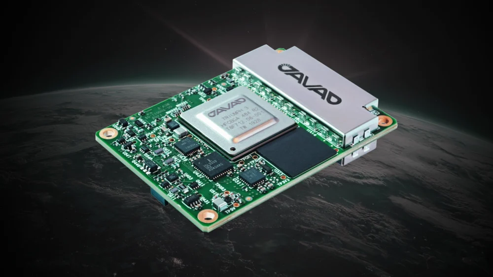
    These advances have been enabled by the evolution of GNSS chipsets. Modern receivers integrate RF front ends, signal processors and navigation engines into compact system-on-chip architectures capable of tracking dozens of signals while running complex positioning algorithms in real time.

    The result is a positioning engine that is no longer confined to a single receiver mounted on a survey pole, but operates as the central reference system for a network of sensors capturing complex environments.

    The maturity of the modern positioning engine

    One of the less visible but most important developments in GNSS over the past decade is the maturation of the positioning engine itself. Early GNSS receivers were essentially signal trackers paired with simple navigation algorithms. Today’s receivers function more like specialized computing platforms optimized for real time estimation.

    At the core of these systems is an estimation framework that continuously evaluates the quality of each observation entering the solution. Carrier phase measurements provide the highest precision available from GNSS, but are highly sensitive to noise, multipath and signal interruptions.

    Modern RTK engines must balance precision with reliability. Rather than assuming every observation is equally valid, processing engines assign dynamic weights based on signal strength, satellite geometry, atmospheric models and measurement stability. These approaches allow receivers to maintain accurate positioning even when portions of the satellite environment become unreliable.

    Solar storms, such as this one in North Carolina, produce beautiful
auroras. They also cause signal disruption and interference for GNSS
systems. Many of the modern RTK engines now have the ability to
filter out this interference and maintain a fix.

    Solar storms, such as this one in North Carolina, produce beautiful auroras. They also cause signal disruption and interference for GNSS systems. Many of the modern RTK engines now have the ability to filter out this interference and maintain a fix.

    The introduction of multi frequency signals also has changed how ambiguity resolution is performed. Earlier RTK systems relied on dual-frequency measurements to estimate ionospheric delay and resolve integer ambiguities. With additional frequencies across multiple constellations, modern receivers apply more advanced ambiguity resolution strategies that improve convergence speed. In practical terms, this means surveyors spend less time waiting for initialization and more time collecting data.

    Modern receivers also incorporate tightly integrated filtering architectures. Extended Kalman filtering frameworks continuously estimate position, velocity, clock bias, atmospheric parameters and measurement noise. These models treat positioning as a dynamic estimation problem rather than a static calculation performed at each epoch. The result is a positioning engine capable of maintaining stable centimeter level solutions even when signal conditions fluctuate. For surveyors working in environments with partial satellite obstruction, intermittent multipath or complex site conditions, these improvements often determine whether a day in the field is productive or not.

    GNSS as foundational infrastructure

    Today, GNSS occupies a unique position in the technology landscape. It is both a mature infrastructure system and a platform for continued innovation. The fundamental architecture of satellite navigation has remained largely consistent for decades, while the ecosystem built around those signals has expanded dramatically.

    In many ways, GNSS has become invisible because it works so well. Surveyors, engineers and geospatial professionals interact with receivers, correction services and data products rather than with the satellites themselves. Positioning is expected to function, much like electricity or cellular connectivity. But under that routine operation lies one of the most sophisticated global infrastructure systems ever constructed.

    At the space segment level, multiple international constellations provide overlapping coverage. The United States’ GPS, Russia’s GLONASS, Europe’s Galileo and China’s BeiDou systems transmit modernized signals designed to improve accuracy, reliability and interoperability. Regional systems such as Japan’s QZSS and India’s NavIC further strengthen coverage.

    This multi-constellation environment represents one of the most significant changes in the GNSS landscape throughout the past two decades. Early survey grade receivers relied primarily on GPS signals, while modern receivers track four or more global constellations simultaneously.

    The impact extends beyond redundancy. Observing more satellites improves geometric strength and allows receivers to maintain robust solutions in environments where single constellation systems would struggle, including urban corridors, forested areas and complex infrastructure sites.

    Signal modernization has expanded the range of measurements available to positioning engines. Additional civilian frequencies such as GPS L5 and Galileo E5 allow better modeling of ionospheric effects and reduced measurement noise, contributing to more stable positioning solutions.

    The most important shift, however, is not in the satellites themselves, but in GNSS’s role within the broader measurement ecosystem.

    In the surveying and geospatial industries, GNSS has evolved from a standalone measurement technique into the spatial reference framework for modern data capture technologies. It now anchors measurement platforms capable of capturing millions of spatial observations.

    In traditional surveying, GNSS remains a primary method for establishing control networks and geodetic reference points, with RTK and post-processed kinematic techniques routinely achieving centimeter-level accuracy.

    In construction and machine control, GNSS enables automated positioning systems that guide heavy equipment using digital terrain models in real time.

    In agriculture, precision farming systems use satellite positioning to guide equipment along exact paths, reducing fuel consumption and optimizing inputs.

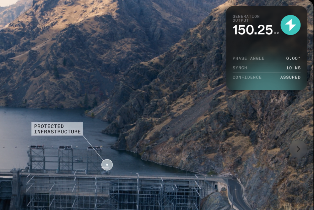
    GNSS also functions as the primary time synchronization system for critical infrastructure, including telecommunications, financial systems and power grids.

    For geospatial professionals, the most significant change is how GNSS interacts with emerging measurement technologies. Rather than acting as a standalone sensor, it now operates as the global reference frame for integrated systems.

    The satellite-derived position establishes a coordinate foundation that other sensors use to build dense spatial models. In a typical workflow, GNSS establishes the reference, inertial sensors track motion, lidar captures geometry and cameras record imagery. All observations rely on the GNSS reference frame to maintain spatial consistency.

    This enables a shift from discrete point measurement to continuous data capture. Instead of collecting individual points, modern platforms capture millions of observations that can be analyzed and extracted as needed.

    GNSS remains the backbone of this process. Even as new sensors emerge, the requirement for a stable global reference frame has not changed. GNSS provides that anchor.

    Sensor fusion and the expanding positioning stack

    While GNSS technology continues to evolve, some of the most significant advances in positioning are occurring through integration with other sensing technologies.

    Trees, such as this 150-year-old tulip poplar, were killers of previous-generation GNSS systems. Robust designs, the modern sensor stack, and powerful algorithms
can now fix reliably in heavy canopy, saving hours of traditional work.

    Trees, such as this 150-year-old tulip poplar, were killers of previous-generation GNSS systems. Robust designs, the modern sensor stack, and powerful algorithms can now fix reliably in heavy canopy, saving hours of traditional work.

    Modern positioning systems operate as part of a broader sensor ecosystem. Satellite observations provide the global reference frame, while inertial measurement units track motion and orientation, lidar sensors capture geometry and visual sensors analyze environmental features.

    Hybrid platforms extend GNSS capability into environments where satellite signals alone may struggle. Several manufacturers now offer handheld systems that combine GNSS receivers with lidar scanning and inertial navigation. Systems such as the CHC Navigation VLi100 integrate GNSS, lidar, inertial sensing and visual positioning into a single instrument. The VLi100 also incorporates the SureFix 2.0 engine, which uses lidar to stabilize the GNSS position for up to 60 ft after signal loss, extending positioning capability in obstructed environments.

    The Tersus S1 SLAM system similarly combines lidar-based mapping with GNSS positioning to capture dense spatial data in complex environments.

    The same principles drive mobile mapping systems designed for infrastructure-scale data capture. Trimble’s MX series, including the MX9 and MX90, combines GNSS positioning, high-accuracy inertial navigation and high-density lidar to capture detailed spatial data while in motion.

    “Sensor fusion is probably the biggest one right now,” said Justin Brooks, sales manager for reality capture at Trimble. “When you combine GNSS with lidar and inertial sensors, you’re not just collecting points anymore. You’re capturing entire environments.”

    Mobile mapping is increasingly used across the energy sector. According to Jason Rosbach, director, energy solutions at Trimble, large renewable energy projects such as utility scale solar and wind developments require rapid spatial documentation across thousands of acres. These systems allow survey teams to capture dense geospatial datasets while maintaining consistent positioning through tightly integrated GNSS and inertial navigation.

    Karl Bradshaw, director, product management, reality capture at Trimble, explained that GNSS remains the core reference.

    “In the MX systems, that GNSS position is the initial core point,” Bradshaw said. “Then the IMU interpolates the vehicle path between those GNSS fixes and provides heading, pitch and roll orientation. Every lidar pulse gets geolocated using that combined solution.”

    Reality capture and the GNSS positioning pyramid

    The convergence of GNSS positioning with lidar scanning, inertial navigation, and SLAM-based mapping is driving the broader adoption of reality capture workflows across the geospatial and infrastructure industries.

    At the core of these systems remains a GNSS-centric positioning pyramid. Satellite observations provide the spatial reference that anchors all other measurements. The additional sensors extend and stabilize that position when conditions become challenging.

    From point measurement to spatial data acquisition

    The integration of GNSS with modern sensing technologies has changed the scale of spatial data collection.

    For most of the 20th century, surveying workflows were based on discrete point measurements. Whether using optical instruments, total stations or early GNSS receivers, surveyors collected individual observations that were later combined to construct maps and models.

    This approach remains essential for control networks and boundary surveys, but many modern applications now operate at a fundamentally different level of data density.

    Lidar scanners, mobile mapping systems and handheld SLAM platforms can collect millions of measurements in minutes. Instead of selecting points, operators move through an environment while continuously capturing geometric observations. These datasets provide a far more detailed representation of the physical world.

    GNSS enables this transition by providing a stable global reference frame. Without it, large point clouds and reality capture datasets would exist only as isolated local models. GNSS allows these datasets to align with engineering design files, geographic information system (GIS) databases and previous survey measurements.

    This spatial consistency makes reality capture practical for large infrastructure projects. Transportation departments can compare roadway conditions over time, utilities can integrate asset models and construction teams can verify progress against design.

    In each of these workflows, GNSS provides the coordinate framework that keeps datasets aligned across time, sensors and project stages.

    The shift from point measurement to continuous data acquisition is one of the most significant changes in geospatial practice in decades.

    Even within these systems, positioning still begins with satellite signals. GNSS remains the foundation. Lidar captures geometry, inertial sensors measure motion and SLAM algorithms track environmental features, all fused with the GNSS position.

    These systems collect dense spatial observations continuously, allowing entire corridors, facilities and infrastructure sites to be captured rapidly. Because these datasets are anchored to GNSS positioning, they maintain consistent spatial reference over time.

    Looking ahead

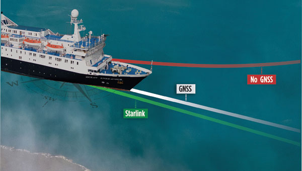
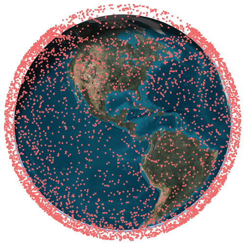
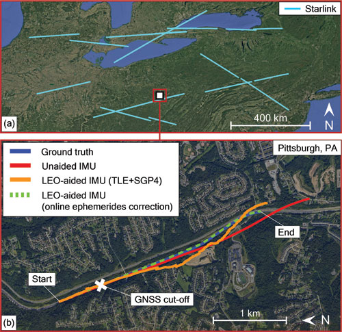
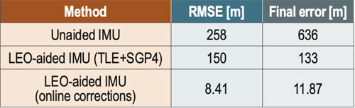
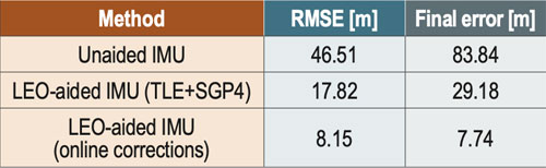
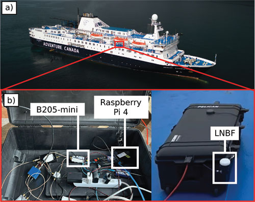
    Another development drawing increasing attention across the positioning industry is the emergence of low Earth orbit (LEO) satellite constellations as potential complements to traditional GNSS systems.

    Unlike GNSS satellites operating at medium-Earth orbit altitudes of roughly 20,000 kilometers, LEO satellites orbit much closer to Earth. This proximity allows their signals to reach receivers with significantly higher signal strength and faster acquisition times.

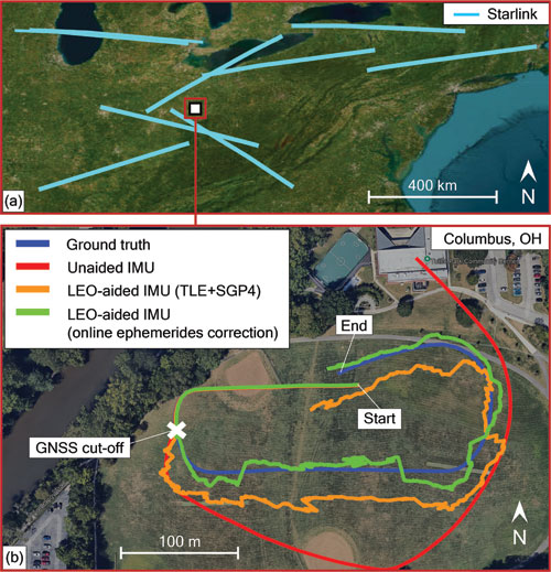
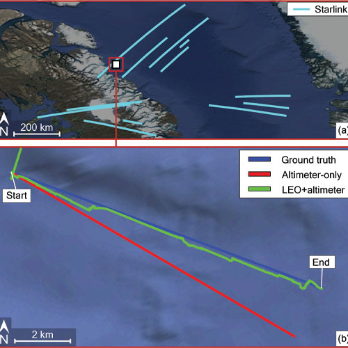
    Because the satellites move rapidly across the sky, they also provide constantly changing geometry that can improve positioning performance in environments where traditional GNSS signals struggle.

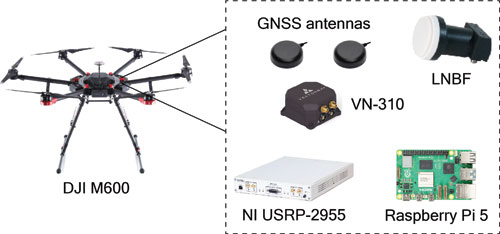
    A number of research groups and commercial companies are now exploring how LEO constellations might augment existing GNSS infrastructure. Some approaches rely on signals from existing communications constellations, while others involve dedicated navigation payloads designed specifically for positioning.

    For surveyors and geospatial professionals, the potential benefit is improved positioning reliability in environments where GNSS signals are degraded. Urban corridors, industrial sites and areas with heavy canopy often limit satellite visibility and introduce multipath interference that complicates carrier-phase measurements.

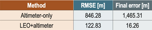
    Additional signals from LEO satellites could provide stronger observations in these environments while also improving the redundancy of positioning solutions.

    The integration of LEO signals would not replace GNSS but rather expand the broader positioning ecosystem that already has begun to emerge through sensor fusion.

    Modern positioning systems increasingly combine GNSS, inertial navigation, lidar, camera and SLAMbased mapping into tightly integrated sensor stacks. GNSS provides the global reference frame, while the other sensors extend and stabilize the positioning solution when satellite visibility becomes limited.

    If LEO navigation signals become widely available, they will likely become another layer within that stack.

    The long-term result could be positioning systems capable of maintaining centimeter-level trajectories across environments that would have been extremely difficult for GNSS-only solutions just a decade ago.

    For the geospatial industry, this evolution represents a continuation of a trend that began decades ago: positioning systems becoming more robust, more integrated, and increasingly capable of capturing the physical world in unprecedented detail.

  • Rohde & Schwarz enables Xona Pulsar signal simulation for next-generation navigation devices

    Rohde & Schwarz enables Xona Pulsar signal simulation for next-generation navigation devices

    New test capability supports device manufacturers preparing for Xona’s commercial LEO navigation constellation.

    Rohde & Schwarz is providing signal simulation capabilities supporting Pulsar, the next-generation satellite navigation service developed by Xona.

    The new functionality enables manufacturers to test Pulsar capabilities in production settings using Rohde & Schwarz signal generators, providing an accessible pathway for validating and scaling devices with next-generation positioning, navigation and timing (PNT).

    As demand grows for more precise and resilient navigation technology, the industry is preparing for a new generation of satellite signals. Xona’s Pulsar constellation, operating in low Earth orbit (LEO), is designed to complement existing GNSS infrastructure such as GPS by delivering stronger signals, improved accuracy, and enhanced resilience against threats and interference.

    The capability will be available as a new software option for the R&S SMBV100B and R&S SMW200A vector signal generators, allowing engineers and manufacturers to test receiver compatibility with Pulsar signals as the new constellation enters scaled deployment. By adding Pulsar simulation to its test portfolio, Rohde & Schwarz enables device developers and manufacturers to begin validating compatibility with the emerging service.

    “Navigation technology is entering a period of rapid evolution,” said Matt Hammond, North America satellite technology manager, Rohde & Schwarz. “By adding Pulsar signal simulation to our signal generator portfolio, Rohde & Schwarz is preparing our customers for the next evolution of satellite navigation. Our goal is to provide the scalable test infrastructure needed to bring these innovations from development into deployment.”

    “Pulsar is designed to upgrade the global navigation infrastructure while remaining compatible with GNSS devices already in use today,” said Bryan Chan, co-founder and VP of strategy at Xona Space Systems. “Test and measurement solutions play an important role in enabling device manufacturers to evaluate compatibility as new signals become available. Rohde & Schwarz brings deep expertise in precision signal generation that helps make this possible.”

    The R&S SMBV100B and R&S SMW200A vector signal generator will soon join Pulsar’s verified ecosystem program recognizing devices and testing solutions validated for compatibility with Pulsar signals. Rohde & Schwarz will showcase its navigation test solutions at Space Symposium 2026, taking place April 13-16 in Colorado Springs.

  • Modern Northstar: Starlink LEO PNT across land, air, stratosphere and Arctic Seas

    Modern Northstar: Starlink LEO PNT across land, air, stratosphere and Arctic Seas

    In January 2015, SpaceX publicly announced its plan to launch Starlink: a mega constellation of nearly 12,000 satellites in low-Earth orbit (LEO) to provide global broadband internet service. In May 2019, the first batch of 60 operational satellites were launched.

    In October 2025, Starlink surpassed 10,000 satellites (see Figure 1). This remarkable achievement means that Starlink has more satellites than all other constellations have ever launched into LEO combined.

    SpaceX is redefining global connectivity, delivering high-speed, low-latency internet anywhere on the planet1. Its civilian system, Starlink, is bridging the digital divide by providing reliable broadband in remote and underserved regions, enabling education, telemedicine and economic growth. Its defense and government variant, Starshield, is offering secure, resilient communications and rapid data transfer for military operations.

    Figure 1 The current constellation of Starlink satellites in LEO, as of January 2026.
    Figure 1 The current constellation of Starlink satellites in LEO, as of January 2026.

    In the midst of the COVID pandemic, in a quiet campus building, the ASPIN Laboratory was busy researching Starlink’s mysterious proprietary signals and the satellites’ poorly known orbits. Having demonstrated the first experimental unmanned aerial vehicle (UAV)2 and ground vehicle3 navigation using Orbcomm LEO satellites, the team’s next grand objective was to exploit Starlink’s signals of opportunity for positioning, navigation, and timing (PNT). At the 2021 ION GNSS+ Conference, the team announced a new era of LEO PNT: the first successful exploitation of Starlink for PNT4. The team designed a cognitive software-defined receiver (SDR) capable of tracking the carrier phase 5 and Doppler6 of Starlink’s so-called pilot tones along with ephemerides error correction algorithms7. The SDR and algorithms were put into test to localize a stationary receiver. Starting from an initial estimate nearly 180 km away, listening to six Starlink satellites resulted in localizing the receiver to within 10 m. This led to worldwide research to study Starlink for PNT, from deciphering Starlink’s downlink orthogonal frequency-division multiplexing (OFDM) signals8,9, to analyzing its ephemerides and timing10,11, to studying the achievable PNT performance12,13.

    This article presents the most advanced LEO PNT results to date with Starlink on four mobile platforms at geographically dispersed locations:

    1. Ground vehicle in Pennsylvania

    2. UAV in Ohio

    3. Extremely high-altitude balloon in New Mexico

    4. Maritime vessel in the Arctic near Greenland

    Exploiting Starlink LEO for PNT: The enablers

    SDR and signal analysis

    Unlike GNSS, non-cooperative LEO satellites such as Starlink do not publicly disclose the structure of their downlink signals, so users must build their own “LEO PNT Interface Control Document (ICD)14. This can be achieved via “reverse-engineering” the signal. A more powerful approach to “reverse-engineering” is via cognitive SDRs, which employ blind signal processing techniques to learn the signals on-the-fly, regardless of the adopted modulation and multiple-access scheme15.

    The most comprehensive characterization to date of Starlink’s downlink signals for PNT was unveiled in16, utilizing the cognitive SDR approach, in which:

    1. The full OFDM beacon was revealed.

    2. Theoretical and experimental description for exploiting Starlink for PNT was provided, showing the maximum achievable carrier-to-noise density ratio (C/N0) under different scenarios: (i) pilot tones versus OFDM-based beacons and (ii) low-gain versus high-gain reception captures.

    3. A Starlink LEO PNT SDR was designed, yielding the first successful extraction of navigation observables (carrier phase, Doppler shift and code phase) from Starlink’s OFDM signals.

    4. A detailed analysis of the quality of Starlink navigation observables, including (i) signal activity and power levels and (ii) timing corrections that contaminate extracted observables along with mitigation strategies.


    Ephemeris and timing error correction

    Unlike GNSS, non-cooperative LEO satellites, such as Starlink, do not broadcast ephemeris and clock data, so users rely on public sources, such as two-line element (TLE) files. However, this data degrades over time due to orbital perturbations, limiting their effectiveness for PNT. Recent research addressed this challenge through five main approaches:

    1. Differential LEO17,18

    2. Machine learning-based orbit prediction19,20

    3. Measurement error correction21,22

    4. Closed-loop ephemeris tracking23,24

    5. Equivalent timing error compensation25,26

    The next sections will showcase experimental LEO PNT results with Starlink signals of opportunity. All experiments utilized the SDR developed in16 and the ephemerides and timing correction methods developed in26-28.


    Ground vehicle navigation in Pennsylvania

    The experiment was conducted in June 2025. The ground vehicle navigated for 3 km in 120 seconds on Interstate 79 by Pittsburgh, Pennsylvania. GNSS signals were available for the first 30 seconds but were virtually cut off for the last 90 seconds, during which the vehicle traversed a 2.25 km trajectory. The vehicle was equipped with a VectorNav VN-310 dual GNSS/INS operating with real-time kinematic (RTK) corrections and a tactical-grade inertial measurement unit (IMU), from which the vehicle’s ground truth was generated. Starlink signals were captured over all eight Ku-band downlink channels using an upward low-noise block with feed-horn (LNBF) and processed at 2.5 MSps via two NI X410 USRPs.

    Figure 2 shows the ground vehicle’s hardware setup.
    Figure 2 shows the ground vehicle’s hardware setup. shows the ground vehicle’s hardware setup.

    The vehicle navigated by fusing Doppler shift measurements from 11 Starlink satellites in a tightly-coupled fashion to aid the IMU, while altimeter measurements were fused in a loosely-coupled fashion. IMU updates were performed at a rate of 200 Hz. Starlink Doppler measurement updates were performed at a rate of 1 Hz with measurement noise variance inversely related to the received C/N0, ranging between 0.05 (m/s)2 and 6.5 (m/s)2, while altimeter updates were performed at a rate of 10 Hz with a measurement noise variance of 3 m2. The vehicle-mounted receiver and LEO satellites’ oscillator qualities were assumed to be that of an oven-controlled crystal oscillator (OCXO). A prior for the vehicle’s position and velocity was obtained from the on-board GNSS system. Starlink LEO satellites’ ephemeris errors were corrected via the equivalent timing error compensation technique in an online fashion as described in28. Each satellite’s equivalent timing error state was initialized with 0, while the relative clock drift state was initialized as the difference between the measured and predicted pseudorange rate.

    An extended Kalman filter (EKF) was used to estimate the state vector, consisting of the vehicle’s orientation, 3D position, 3D velocity and the IMU’s 3D gyroscope and accelerometer biases along with the relative clock drift error between the receiver and each LEO satellite. The Starlink satellites’ orbits were generated by propagating TLE files with SGP4 for the duration of the experiment. The navigation solution was generated using three approaches:

    1. Unaided IMU: The vehicle navigates via open-loop IMU measurements when GNSS measurements are unavailable.

    2. LEO-aided IMU with TLE+SGP4 ephemerides: The vehicle fuses LEO measurements with IMU and altimeter measurements while incorporating TLE+SGP4 ephemerides in the navigation filter.

    3. LEO-aided IMU with online ephemerides corrections: The vehicle fuses LEO measurements with IMU and altimeter measurements. Starting with TLE+SGP4 ephemerides, the navigation filter estimates an equivalent timing error for each satellite as described in28.

    Figure 3 shows the Starlink satellite trajectories, as well as the vehicle’s ground truth and estimated trajectories with the three navigation approaches. The unaided IMU solution drifted to a 3D position root mean squared error (RMSE) of 258 m from the truth trajectory. The LEO-aided IMU solution that incorporated the erroneous TLE+SGP4 ephemerides resulted in a 3D position RMSE of 150 m, while the navigation solution employing the online ephemeris correction method resulted in an RMSE of 8.41 m. Table 1 summarizes the navigation results.
    Figure 3 shows the Starlink satellite trajectories, as well as the vehicle’s ground truth and estimated trajectories with the three navigation approaches. The unaided IMU solution drifted to a 3D position root mean squared error (RMSE) of 258 m from the truth trajectory. The LEO-aided IMU solution that incorporated the erroneous TLE+SGP4 ephemerides resulted in a 3D position RMSE of 150 m, while the navigation solution employing the online ephemeris correction method resulted in an RMSE of 8.41 m.
    Table 1 summarizes the navigation results.
    Table 1 summarizes the navigation results.

    UAV navigation in Ohio

    The experiment was conducted in August 2025. A DJI M600 UAV navigated for 500 m in 75 seconds in Columbus, Ohio. GNSS signals were available for the first 20 seconds of the experiment but were virtually cut off for the last 55 seconds, during which the UAV traversed a 370 m trajectory. The UAV was equipped with a VectorNav VN-310 dual GNSS/INS operating with RTK corrections and a tactical-grade IMU, from which the UAV’s ground truth was generated. Starlink signals were captured from the 4 low-side Ku-band channels using an upward LNBF and processed at 2.5 MSps via an NI 2955 USRP. Figure 4 shows the UAV’s hardware setup.

    Figure 4 UAV’s hardware setup.
    Figure 4 UAV’s hardware setup.

    The UAV navigated by fusing Doppler shift measurements from nine Starlink satellites in a tightly-coupled fashion to aid the IMU, while altimeter measurements were fused in a loosely-coupled fashion. IMU updates were performed at a rate of 200 Hz. Starlink Doppler measurement updates were performed at a rate of 1 Hz with measurement noise variance inversely related to the received C/N0, ranging between 0.09 (m/s)and 6.75 (m/s)2, while altimeter updates were performed at a rate of 10 Hz with a measurement noise variance of 3 m2. The UAV-mounted receiver and LEO satellites’ oscillator qualities were assumed to be that of an OCXO. A prior for the UAV position and velocity was obtained from the UAV’s on-board GNSS system. Starlink LEO satellites’ ephemeris errors were corrected via the equivalent timing error compensation technique in an online fashion as described in 28. Each satellite’s equivalent timing error state was initialized with 0, while the relative clock drift state was initialized as the difference between the measured and predicted pseudorange rate.

    An EKF was used to estimate the state vector, consisting of the UAV’s orientation, 3D position, 3D velocity and the IMU’s 3D gyroscope and accelerometer biases, along with the relative clock drift error between the receiver and each LEO satellite. The Starlink satellites’ orbits were generated by propagating TLE files with SGP4 for the duration of the experiment. The navigation solution was generated using the three approaches described in Section II.

    Figure 5 shows the Starlink satellite trajectories, as well as the UAV’s ground truth and estimated trajectories with the three different navigation approaches. The unaided IMU solution drifted to a 3D position RMSE of 46.51 m from the truth trajectory. The LEO-aided IMU solution that incorporated the erroneous TLE+SGP4 ephemerides resulted in a 3D position RMSE of 17.82 m, while the navigation solution employing the online ephemeris correction method resulted in an RMSE of 8.15 m. Table 2 summarizes the navigation results.

    Figure 5 Experimental results of Doppler-based UAV navigation with Starlink: (a) trajectories of the nine Starlink satellites used to navigate the UAV and (b) UAV’s trajectory (blue) and estimated trajectories via the unaided IMU solution (red) and LEO-aided IMU solutions when incorporating the (i) uncorrected TLE+SGP4 ephemerides (orange) and (ii) online ephemeris correction (green).
    Figure 5 Experimental results of Doppler-based UAV navigation with Starlink: (a) trajectories of the nine Starlink satellites used to navigate the UAV and (b) UAV’s trajectory (blue) and estimated trajectories via the unaided IMU solution (red) and LEO-aided IMU solutions when incorporating the (i) uncorrected TLE+SGP4 ephemerides (orange) and (ii) online ephemeris correction (green).
    Table 2 Experimental results: UAV 3D position errors.
    Table 2 Experimental results: UAV 3D position errors.

    High-altitude balloon navigation in New Mexico

    The experiment was conducted in July 202429. The balloon was launched from the Moriarty Municipal Airport in Moriarty, New Mexico, and landed just south of Mountainair, New Mexico, traveling a horizontal distance of about 105 km south with a 3D distance of about 119 km. The balloon reached a peak altitude of about 25.3 km (83,128 ft) above sea level. A specific time period was studied to evaluate utilization of Doppler observables for navigation at an elevation of 82,177 ft. During this period, five different Starlink satellites were tracked over a 50-second period, during which the balloon traveled 948 m.  The balloon was equipped with a VectorNav VN-200 GNSS/INS, from which the ground truth trajectory was generated. Starlink signals were captured over two Ku-band downlink channels using an upward LNBF and processed at 2.5 MSps via two Ettus B205-mini USRPs. Figure 6 shows the balloon’s hardware setup.

    Figure 6 (a)-(c) High-altitude balloon’s hardware setup. (d) OHIO in New Mexico, left to right: Jennifer Sanderson, Zak Kassas, Will Barrett and the Icarus Balloon. (e) Balloon launch.
    Figure 6 (a)-(c) High-altitude balloon’s hardware setup. (d) OHIO in New Mexico, left to right: Jennifer Sanderson, Zak Kassas, Will Barrett and the Icarus Balloon. (e) Balloon launch.

    The balloon navigated by fusing Doppler shift measurements from five Starlink satellites and altimeter measurements via an EKF. The dynamic model of the high-altitude balloon was chosen as a velocity random walk model, with acceleration process noise spectra set to 0.5 m2/s3 in the in the East, North and 0.8 m2/s3 in the in Up directions, respectively. Starlink Doppler measurement updates were performed at a rate of 10 Hz with measurement noise variance inversely related to the received C/N0, ranging between 1.40 (m/s)2 and 7.01 (m/s)2, while altimeter updates were performed at rate of 10 Hz with a measurement noise variance of 1 m2. The process noise covariance for the clock states was constructed according to an OCXO clock quality. A prior for the balloon’s position and velocity was obtained from the on-board GNSS system. Ephemeris data for each satellite was obtained from offline SGP4-propagated TLE, with epoch time corrections made by minimizing the residuals between predicted Doppler and measured Doppler26,27.

    The EKF state vector consisted of the balloon’s 3D position and 3D velocity along with the relative clock drift error between the receiver and each LEO satellite. The navigation solution was generated using (i) an open-loop approach, which simply propagated the states via the dynamical model and (ii) the LEO+altimeter approach.

    Figure 7 shows the balloon’s ground truth and estimated trajectories with the two different navigation approaches. The open-loop solution drifted to a 3D position RMSE of 83.34 m from the truth trajectory, while the LEO-aided solution resulted in an RMSE of 12.28 m. Table 3 summarizes the navigation results.

    Figure 7 Experimental results of Doppler-based high-altitude balloon navigation with Starlink: (a) trajectories of five Starlink satellites used and (b) balloon’s trajectory (blue) and estimated trajectories via the open-loop solution (red) and LEO-aided solution (green).
    Figure 7 Experimental results of Doppler-based high-altitude balloon navigation with Starlink: (a) trajectories of five Starlink satellites used and (b) balloon’s trajectory (blue) and estimated trajectories via the open-loop solution (red) and LEO-aided solution (green).
    Table 3 Experimental results: High-altitude ballon 3D position errors.
    Table 3 Experimental results: High-altitude ballon 3D position errors.

    Maritime navigation in the Arctic

    The experiment was conducted in August 202430. The vessel navigated for 8.5 km in 20 minutes off the shore of Baffin Island, Nunavut, Canada. Starlink signals were captured over the third Ku-band downlink channel using an upward LNBF and processed at 2.5 MSps via a B205-mini USRP and a Raspberry Pi 4. Figure 8 shows the vessel’s hardware setup.

    Figure 8 Vessel’s hardware setup.
    Figure 8 Vessel’s hardware setup.

    The vessel navigated by fusing Doppler shift measurements from 12 Starlink satellites and altimeter data via an EKF. The dynamic model of the vessel was chosen as a velocity random walk model. Starlink Doppler measurement and altimeter data updates were both performed at a rate of 10 Hz with measurement noise variances of 4.5 (m/s)2 and 3 m2, respectively. The vessel-mounted receiver and the LEO satellites’ oscillator qualities were assumed to be that of an OCXO. The vessel’s position states were initialized from the true position obtained from the on-board GNSS system. The velocity was initialized from the true velocity but with a 10˚ clockwise error with respect to the vessel’s direction-of-motion. The Starlink satellites’ orbits were generated by propagating TLE files with SGP4 for the duration of the experiment. Ephemeris errors were corrected by adjusting the TLE epoch time for eachsatellite26,27 to minimize the residuals between predicted Doppler and measured Doppler.

    An EKF was used to estimate the state vector, consisting of the vessel’s 3D position, 3D velocity and the relative clock drift errors between the receiver and each LEO satellite. The navigation solution was generated via two approaches: (i) using only altimeter data and (ii) using LEO Doppler fused with altimeter data.

    Figure 9 shows the Starlink satellite trajectories, as well as the vessel’s ground truth and estimated trajectories with the two navigation approaches. The altimeter-only solution drifted to a 3D position RMSE of 846 m from the truth trajectory. The LEO+altimeter solution resulted in a 3D position RMSE of 123 m. Table 4 summarizes the navigation results.

    Figure 9 Experimental results of Doppler-based vessel navigation with Starlink: (a) trajectories of the 12 Starlink satellites used to navigate the vessel and (b) vessel’s true trajectory (blue) and estimated trajectories using (i) only an altimeter (red) and (ii) using LEO + altimeter (green).
    Figure 9 Experimental results of Doppler-based vessel navigation with Starlink: (a) trajectories of the 12 Starlink satellites used to navigate the vessel and (b) vessel’s true trajectory (blue) and estimated trajectories using (i) only an altimeter (red) and (ii) using LEO + altimeter (green).
    Table 4 Experimental results: Vessel 3D position errors.
    Table 4 Experimental results: Vessel 3D position errors.

    Acknowledgments

    This work was supported in part by the Office of Naval Research (ONR) under Grants N00014-22-1-2242 and N00014-22-1-2115, in part by the Air Force Office of Scientific Research (AFOSR) under Grant FA9550-22-1-0476, in part by the U.S. Department of Transportation under Grant 69A3552348327 for the CARMEN+ University Transportation Center, in part by The Aerospace Corporation under Award 4400000428, and in part by the Laboratory Directed Research and Development program at Sandia National Laboratories under award 2543953. Sandia National Laboratories is a multimission laboratory managed and operated by National Technology & Engineering Solutions of Sandia LLC, a wholly owned subsidiary of Honeywell International Inc., for the U.S. Department of Energy’s National Nuclear Security Administration under contract DENA0003525. This paper describes objective technical results and analysis. Any subjective views or opinions that might be expressed in the paper do not necessarily represent the views of the U.S. Department of Energy or the United States Government.

    The authors would like to thank Vasilios Konstantacos, Jackson Morris, Ethan Shaw, Khaled Hamil, Aiden Short and Andrew Ye for constructing the balloon’s payload; Mark Andrews for supervising the payload design; and Prabodh Jhaveri, Danny Bowman, Mike Fleigle and Justin LaPierre for helping with launch and recovery of the balloon. The authors would also like to thank The Explorers Club and Adventure Canada for their help with data collection in the Arcitc. The authors would like to thank VectorNav for supplying the VN-200.

    References

    1. A. Yadav, M. Agarwal, S. Agarwal, and S. Verma, “Internet from space anywhere and anytime – Starlink,” in Proceedings of International Conference on Advancement in Electronics & Communication Engineering, pp. 1-8, 2022.

    2. J. Morales, J. Khalife, A. Abdallah, C. Ardito, and Z. Kassas, “Inertial navigation system aiding with Orbcomm LEO satellite Doppler measurements,” in Proceedings of ION GNSS+ Conference, pp. 2718-2725, 2018.

    3. Z. Kassas, J. Morales, and J. Khalife, “New-age satellite-based navigation – STAN: simultaneous tracking and navigation with LEO satellite signals,” Inside GNSS Magazine, (14)4, pp. 56-65, 2019.

    4. M. Neinavaie, J. Khalife, and Z. Kassas, “Exploiting Starlink signals for navigation: first results,” in Proceedings of ION GNSS+ Conference, pp. 2766-2773, 2021.

    5. J. Khalife, M. Neinavaie, and Z. Kassas, “The first carrier phase tracking and positioning results with Starlink LEO satellite signals,” IEEE Transactions on Aerospace and Electronic Systems, (58)2, pp. 1487-1491, 2022.

    6. M. Neinavaie, J. Khalife, and Z. Kassas, “Acquisition, Doppler tracking, and positioning with Starlink LEO satellites: first results,” IEEE Transactions on Aerospace and Electronic Systems, (58)3, pp. 2606-2610, 2022.

    7. Z. Kassas, M. Neinavaie, J. Khalife, N. Khairallah, S. Kozhaya, J. Haidar-Ahmad, and Z. Shadram, “Enter LEO on the GNSS stage: navigation with Starlink satellites,” Inside GNSS Magazine, (16)6, pp. 42-51, 2021.

    8. T. Humphreys, P. Iannucci, Z. Komodromos, and A. Graff, “Signal structure of the Starlink Ku-band downlink,” IEEE Transactions on Aerospace and Electronic Systems, (59)5, pp. 6016-6030, 2023.

    9. M. Neinavaie and Z. Kassas, “Cognitive sensing and navigation with unknown OFDM signals with application to terrestrial 5G and Starlink LEO satellites,” IEEE Journal on Selected Areas in Communications, (42)1, pp. 146-160, 2024.

    10. S. Hayek and Z. Kassas, “Warm start navigation with non-cooperative LEO satellites via online ephemeris error estimation,” in Proceedings of IEEE/ION Position, Location, and Navigation Symposium, pp. 112-123, 2025.

    11. W. Qin, A. Graff, Z. Clements, Z. Komodromos, and T. Humphreys, “Timing properties of the Starlink Ku-band downlink,” IEEE Transactions on Aerospace and Electronic Systems, (62), pp. 727-744, 2026.

    12. H. More, E. Cianca, and M. De Sanctis, “Comparing positioning performance of LEO mega-constellations and GNSS in urban canyons,” IEEE Access, (12), pp. 24465-24482, 2024.

    13. Z. Kassas and J. Saroufim, “LEO PNT frameworks for non-cooperative satellites with poorly known ephemerides: open-loop SGP4, tracking, and differential,” IEEE Aerospace and Electronic Systems Magazine, (40)1, pp. 46-71, 2025.

    14. S. Kozhaya, H. Kanj, and Z. Kassas, “Multi-constellation blind beacon estimation, Doppler tracking, and opportunistic positioning with OneWeb, Starlink, Iridium NEXT, and Orbcomm LEO satellites,” in Proceedings of IEEE/ION Position, Location, and Navigation Symposium, pp. 1184-1195, 2023.

    15. S. Kozhaya, S. Hayek, and Z. Kassas, “Cognitive beacon estimation of unknown LEO satellites signals of opportunity for PNT,” IEEE Journal on Selected Areas in Communications, pp. 1-16, 2026, in-press.

    16. S. Kozhaya, J. Saroufim, and Z. Kassas, “Unveiling Starlink for PNT,” NAVIGATION, Journal of the Institute of Navigation, (72)1, pp. 1-35, 2026.

    17. J. Khalife and Z. Kassas, “Performance-driven design of carrier phase differential navigation frameworks with megaconstellation LEO satellites,” IEEE Transactions on Aerospace and Electronic Systems, (59)3, pp. 2947–2966, 2023.

    18. M. Hasan, M. Kabir, M. Islam, S. Han, and W. Shin, “A double difference Doppler shift-based positioning framework with ephemeris error correction of LEO satellites,” IEEE Systems Journal, (18)4, pp. 2157-2168, 2024.

    19. Z. Kassas, S. Hayek, and J. Haidar-Ahmad, “LEO satellite orbit prediction via closed-loop machine learning with application to opportunistic navigation,” IEEE Aerospace and Electronic Systems Magazine, (40)1, pp. 34-49, 2024.

    20. K. Selvan, A. Siemuri, F. Prol, P. Välisuo, and H. Kuusniemi, “Machine learning for LEO and MEO satellite Orbit prediction,” in Proceedings of ION GNSS+ Conference, pp. 3556 -3571, 2024.

    21. J. Saroufim and Z. Kassas, “Ephemeris and timing error disambiguation enabling precise LEO PNT,” IEEE Transactions on Aerospace and Electronic Systems, (61)3, pp. 6138–6153, 2025.

    22. J. Saroufim and Z. Kassas, “LEO ephemeris error modeling enabling long baseline correction for improved PNT,” in Proceedings of IEEE/ION Position, Location, and Navigation Symposium, pp. 625–630, 2025.

    23. N. Khairallah and Z. Kassas, “Ephemeris tracking and error propagation analysis of LEO satellites with application to opportunistic navigation,” IEEE Transactions on Aerospace and Electronic Systems, (60)2, pp. 1242–1259, 2024.

    24. S. Kozhaya, J. Saroufim, S. Hayek, P. El-Kouba, and Z. Kassas, “Light will guide you: passive joint DOA/FOA sensing, tracking, and navigation with unknown LEO satellites,” in Proceedings of IEEE/ION Position, Location, and Navigation Symposium, pp. 716–727, 2025.

    25. Y. Du, H. Qin, and C. Zhao, “LEO satellites/INS integrated positioning framework considering orbit errors based on FKF,” IEEE Transactions on Instrumentation and Measurement, (73), pp. 1-14, 2024.

    26. S. Hayek, J. Saroufim, and Z. Kassas, “Analysis and correction of LEO satellite propagation errors with application to navigation,” in Proceedings of ION GNSS+ Conference, pp. 1800 -1811, 2024.

    27. S. Hayek and Z. Kassas, “Modeling and compensation of timing and spatial ephemeris errors of non-cooperative LEO satellites with application to PNT,” IEEE Transactions on Aerospace and Electronic Systems, (61)3, pp. 5579-5593, 2025.

    28. S. Hayek and Z. Kassas, “A reduced-order model of simultaneous tracking and navigation with LEO satellites”, IEEE Aerospace and Electronic Systems Magazine, in preparation.

    29. W. Barrett, J. Sanderson, S. Kozhaya, J. Saroufim, and Z. Kassas, “Evaluation of Starlink LEO satellite signals for high-altitude platform station opportunistic navigation,” in IEEE International Conference on Wireless for Space and Extreme Environments, pp. 100-105, 2024.

    30. W. Barrett, S. Kozhaya, Z. Kassas, and D. Marsh, “Navigating the Arctic Circle with Starlink and OneWeb LEO satellites,” in Proceedings of IEEE Military Communications Conference, pp. 1–6, 2025.

    Authors

    Zaher (Zak) M. Kassas is the TRC Endowed Chair in Intelligent Transportation Systems and Professor of Electrical and Computer Engineering at The Ohio State University (OSU). He is also Director of the Autonomous Systems Perception, Intelligence, & Navigation (ASPIN) Laboratory and Director of the U.S. Department of Transportation Center for Automated Vehicles Research with Multimodal AssurEd Navigation (CARMEN).

    Samer Hayek is a Ph.D. student at OSU and member of the ASPIN Laboratory.

    Will Barrett was a member of the ASPIN Laboratory.

    Sharbel Kozhaya is a Senior Research Associate at the ASPIN Laboratory.

    Paul El-Kouba is a Ph.D. student at OSU and member of the ASPIN Laboratory.

    Faezeh Mooseli is a Ph.D. student at OSU and member of the ASPIN Laboratory.

    Jennifer Sanderson is a Ph.D. student at OSU and member of the ASPIN Laboratory. She is also an R&D Engineer with Sandia National Laboratories.

    Joe Saroufim is a Ph.D. student at OSU and member of the ASPIN Laboratory.

  • JAVAD introduces US-built GNSS board for LEO applications

    JAVAD introduces US-built GNSS board for LEO applications

    JAVAD GNSS has announced the TR-2S LEO, a compact GNSS OEM board designed and manufactured at the company’s headquarters in San Jose, California. The TR-2S LEO delivers high-precision GNSS positioning for low Earth Orbit (LEO) missions.

    Developed for customers requiring high-integrity navigation performance under the demanding conditions of space, the TR-2S LEO integrates radiation-tolerant, space-hardened electronics with patented spoofing and jamming detection to support, secure and protect continuous GNSS operation. The board tracks 874 channels across all major GNSS constellations, enabling robust and real-time position, velocity, time and measurements (PVT) with multi-frequency resilience.

    JAVAD GNSS brings more than two decades of flight heritage, with OEM boards deployed on most commercial launch vehicles worldwide, including the Vega program of the European Space Agency (ESA). The company continues to build upon its experience, now with focused concentration on LEO-based applications with technologies like the TR-2S LEO and the SpaceAnt-G3T OEM GNSS antenna. The SpaceAnt-G3T features a stable phase center and is usable for single-, dual- and triple-frequency applications.

    “The TR-2S LEO reflects our commitment to delivering mission-critical GNSS solutions engineered and manufactured entirely in the United States,” said Tom Hunter, senior vice president, Aerospace and Defense Solutions at JAVAD GNSS. “As commercial space operations expand, our customers need a navigation platform they can trust — one built on proven flight heritage, radiation-hardened design, and the technical support to see their missions succeed. That’s what we deliver.”

    The TR-2S LEO is adaptable to a wide range of commercial launch vehicles, spacecraft and high-dynamic applications.

  • TrustPoint demonstrates GPS-independent navigation signals to orbit

    TrustPoint demonstrates GPS-independent navigation signals to orbit

    TrustPoint has transmitted its first Low-Earth Orbit Navigation System (LEONS) time-transfer and tracking signals from a ground node to spacecraft in orbit. The milestone advances the development of commercial navigation infrastructure independent of GPS.

    GNSS satellites require knowledge of their own time and orbital position to provide accurate data to Earth-based users. Most LEO spacecraft currently rely on GPS or medium-Earth orbit (MEO) signals for that information. Interference and jamming are increasingly affecting these LEO connections, degrading or blocking signals.

    LEONS provides GPS-independent time transfer and orbit tracking. Initially developed for TrustPoint’s planned constellation, the system can be adapted for other LEO operators requiring timing and navigation for their spacecraft. The ground-to-space infrastructure is designed to support a GPS-independent PNT layer in orbit.

    “With the pace of modern threats accelerating, the difference between concepts and capabilities matters,” said Nicole Hilliard, director of government programs at TrustPoint. “This milestone demonstrates that commercial partners can field resilient, GPS-independent PNT capabilities that strengthen national security architectures and justify continued investment in companies that deliver.”

    The demonstration supports TrustPoint’s participation in the SpaceWERX AltPNT Challenge, which awarded the company two contracts to develop alternative PNT capabilities. The program seeks to deploy new options for precise, dual-use PNT systems.

  • SpacePNT completes qualification testing for second-gen spaceborne GNSS receiver

    SpacePNT completes qualification testing for second-gen spaceborne GNSS receiver

    SpacePNT SA, a global provider of high-accuracy, radiation-tolerant spaceborne GNSS receiver equipment for missions ranging from Earth to cislunar orbit, has completed extensive qualification testing of its second-generation product, including vibration, shock, thermal vacuum and electromagnetic compatibility tests.

    The multi-frequency, multi-GNSS receiver resulted from two European Space Agency (ESA) ARTES Competitive & Growth (C&G) development projects supported by ESA and the Swiss Space Office.

    The first project enabled SpacePNT to develop an industrialized second-generation product for large-scale production targeting low-Earth orbit, LEO position-navigation-timing and geostationary orbit telecommunications constellations. The receiver includes a proprietary Precise Orbit Determination algorithm that provides sub-decimeter real-time positioning and timing aboard spacecraft. The company validated the POD algorithm in a hardware-in-the-loop environment and retrofitted it into two first-generation flight models delivered to a customer for satellite integration.

    Under the second project, SpacePNT developed a Radiation Hardiness Assurance approach for long-duration missions in harsh radiation environments. ESA’s GENESIS satellite mission, which will operate in a challenging medium Earth orbit environment, will be the first to use this RHA approach. SpacePNT will supply the mission’s GNSS receiver equipment.

    Though the second-generation receiver uses largely the same hardware, software and firmware technology as the company’s flight-proven first-generation product, SpacePNT performed a complete qualification campaign to validate design changes.

    After passing all qualification and performance tests, SpacePNT will begin manufacturing first flight models of its second-generation products for several customers. The receivers will fly on demanding Earth observation, in-orbit servicing and space exploration missions at altitudes from LEO through medium Earth orbit, geosynchronous transfer orbit, geostationary orbit and lunar distances.

    The views expressed herein do not reflect the official opinion of the European Space Agency.

  • UAE Space Center, Thales Alenia Space partner on LEO-PNT navigation system

    UAE Space Center, Thales Alenia Space partner on LEO-PNT navigation system

    The National Space Science and Technology Center (NSSTC) and Thales Alenia Space, a joint venture between Thales (67%) and Leonardo (33%), are cooperating to explore opportunities in low-Earth orbit (LEO) space navigation systems.

    The growing dependence of economies and daily lives on Global Navigation Satellite Systems is driving innovation and leading to technologies that deliver enhanced resilience and improved performance. At the forefront, low-Earth orbit positioning, navigation and timing (PNT) is emerging as a game-changer.

    The LEO-PNT satellites seek to provide guaranteed and sovereign centimeter location accuracy, robustness, resistance against jamming and spoofing, and low latency. LEO-PNT will serve emerging applications such as high-level autonomy cars, including persistent coverage in dense urban areas, unmanned aerial and maritime vehicles, and 5G/6G ground telecommunication network synchronization.

    Recognizing the strategic importance of LEO-PNT, the NSSTC is working with Thales Alenia Space to explore opportunities in this domain. The partnership was formalized through the signing of a memorandum of understanding at the Paris Air Show 2025, establishing a framework for cooperation. Building on that foundation, both parties signed an agreement marking the start of joint technical studies and engineering activities focused on regulatory protection and system design elements for LEO-PNT.

    The collaboration reflects a vision to explore pathways that can enhance the robustness and sovereignty of future navigation services while deepening international cooperation and knowledge exchange between the United Arab Emirates and Europe in the field of space technology.

    “This collaboration marks an important step toward building the UAE’s next-generation navigation capabilities,” said Ali Al Shehhi, director of NSSTC. “LEO-PNT will bring a new level of precision and resilience, and working with Thales Alenia Space allows us to accelerate our path toward a sovereign system that supports the UAE’s long-term strategic vision.”

    “LEO-PNT is a game changer in satellite navigation in terms of increased precision, resilience and signal penetration, enabling new applications and economic growth,” said Hervé Derrey, CEO of Thales Alenia Space. “We are proud to offer our expertise in satellite navigation to the NSSTC, thereby strengthening our collaboration with the United Arab Emirates in the space domain.”

  • Septentrio demos tracking of Xona’s first LEO PNT satellite

    Septentrio demos tracking of Xona’s first LEO PNT satellite

    Septentrio and xonaspace.com have signed a Memorandum of Understanding (MOU) to deepen their collaboration on next-generation positioning and timing solutions.

    The agreement builds on Xona’s recent successful launch of Pulsar-0, its first production class LEO PNT satellite. Within days of launch, Septentrio began tracking and analyzing Pulsar signals, an early milestone toward unlocking the service’s full potential.

    Together, the companies will continue joint testing and validation to prove Pulsar’s full capabilities, including:
    •    native centimeter-level accuracy
    •    100x stronger signal strength that reaches indoors and under dense foliage
    •    robust protection against jamming and spoofing.

    Through this partnership, Septentrio and Xona will advance receiver development, evaluate real-world performance, and explore commercial opportunities across diverse set of industrial and defense applications. Potential use cases span drones and autonomous vehicles, precision agriculture, construction and mining, robotics, timing and critical infrastructure.

    This collaboration marks a significant step toward addressing the growing demand for robust, high-precision navigation in challenging environments. The MOU underscores a shared vision of both companies to advance satellite-based navigation technology and unlock the potential of hybrid GNSS-LEO solutions.

  • Safran’s Skydel simulator now supports Xona’s Pulsar LEO navigation signals

    Safran’s Skydel simulator now supports Xona’s Pulsar LEO navigation signals

    Safran Electronics & Defense‘s Skydel GNSS simulation platform is now fully certified to support simulation of Xona Space Systems’ low-Earth orbit positioning, navigation and timing (LEO-PNT) signal, Pulsar.

    According to the companies, this certification is the culmination of a rigorous multi-phase validation program jointly led by Safran and Xona engineering teams. It underscores Safran’s commitment to advancing robust, high-fidelity testing for next-generation LEO-PNT services. With this milestone, engineers can now use Skydel to evaluate Pulsar’s performance in environments that reflect real-world complexity, interference and operational demands.

    Skydel now simulates Xona’s Pulsar X1 signals, delivering centimeter-level precision, 100x signal strength and enhanced resilience — capabilities that Pulsar will soon bring to orbit.

    “With Skydel-powered simulators certified for Pulsar X1, our customers have more possibilities than ever,” said Pierre-Marie Le Veel, program director of PNT simulation at Safran Electronics & Defense. “They can test LEO and legacy constellations side by side, introduce complex interference, and explore entirely new scenario combinations — all from a single, flexible platform. This is a major step forward in enabling engineers to push the boundaries of GNSS testing.”

    Beyond accuracy, Skydel enables advanced resilience testing, including jamming, spoofing and other NAVWAR threats. Its modular, future-ready architecture ensures seamless integration of new Pulsar signal types and constellation updates, offering the agility needed to keep pace with the evolving LEO PNT landscape and demands for trusted, high-integrity PNT.

    “Validation is the bridge between innovation and trust,” said Tyler Reid, CTO of Xona. “By replicating Pulsar at full fidelity, Skydel empowers engineers to design and validate solutions for the most demanding navigation and timing challenges — without waiting for on-orbit availability.”

    Skydel’s certified Pulsar simulation capability is available now to partners and customers worldwide.

  • Intellian, Eutelsat develop portable military-grade terminal for alternative PNT

    Intellian, Eutelsat develop portable military-grade terminal for alternative PNT

    Intellian Technologies Inc., a leading global provider of satellite communication antennas and ground gateway solutions, and Eutelsat, a GEO-LEO operator in satellite communications, have developed a portable, fully integrated military-grade Manpack for Eutelsat’s OneWeb low-Earth orbit (LEO) network.

    With auto detected resilient GNSS (R-GNSS), the military-grade unit enables external support of an alternative positioning, navigation and timing (Alt-PNT) to ensure operation in GPS-denied environments.

    Developed for defense and government, the unit provides the uninterrupted, dependable Eutelsat OneWeb LEO connectivity. It was created to address the urgent need for next-generation LEO capabilities within the broader military satellite communications domain.

    Designed for rapid deployment, the Manpack is small and light to fit a standard military rucksack. It features one-touch network acquisition for immediate operation even in demanding and high-pressure conflict regions. It is optimized for low power consumption to maximize mission duration for up to five hours on external batteries depending on usage.

    Built to battlefield-ready specifications, the Manpack is designed for Ingress Protection (IP67), as well as the U.S. Military Standards for Environmental Engineering (MIL-STD-810H) and Electromagnetic Compatibility (MIL-STD-461). This ensures exceptional durability for Communications-On-The-Pause (COTP) to personnel on front lines and mission-critical operations.

  • ESA’s Celeste LEO-PNT demonstrator mission set to launch in December

    ESA’s Celeste LEO-PNT demonstrator mission set to launch in December

    The European Space Agency (ESA) has confirmed plans to launch the first two satellites in its low-Earth orbit (LEO) positioning navigation and timing (PNT) constellation in the second half of December 2025. The launch will use a Rocket Lab Electron Vehicle, marking Europe’s first venture into LEO-based satellite navigation.

    The LEO-PNT in-orbit demonstrator mission, called Celeste, aims to test satellite navigation capabilities in LEO and evaluate its integration with existing medium-Earth orbit (MEO) systems.

    Celeste features a constellation of ten satellites that will fly close to Earth to test innovative signals across various frequency bands. The first two Celeste satellites, built in parallel by GMV and Thales Alenia Space, are set to launch in the coming months.

    The dedicated Electron rocket launch will place both satellites in orbit at 510 km altitude. The launch window extends for three months beginning in mid-December 2025, with operations conducted from Rocket Lab’s New Zealand facility.

    ESA Director of Navigation, Javier Benedicto, said, “We are thrilled to see the LEO-PNT demonstration advancing so quickly, with less than two years between mission kick-off and launch. This launch ensures the first European LEO-PNT satellites are in space before spring 2026, crucial for bringing the frequencies into use in compliance with the International Telecommunications Union.”

    Galileo’s “Daughter Mission”

    The name Celeste pays homage to Maria Celeste, Galileo Galilei’s daughter, as the two shared a strong emotional and intellectual bond, with the daughter honoring her father’s astronomical interest. This symbolic connection links the pioneering work of the father of modern astronomy to contemporary navigation systems, with Celeste serving as a bridge between Galileo’s groundbreaking discoveries and today’s satellite-based positioning technology.

    The demonstrator satellites for Galileo, launched in 2005 and 2008, were called GIOVE, after the Italian word for Jupiter. This name also paid tribute to Galileo’s achievements in discovering the planet’s four largest Moons which were used to determine longitude from anywhere on Earth.

    System Advantages

    The initial Pathfinder A satellites are CubeSats measuring 12U and 16U formats, comparable to suitcase size and weighing approximately 20 kg to 30 kg. These satellites will broadcast in L-band and S-band frequencies and operate for at least six months following orbital commissioning.

    The larger, more complex Pathfinder B satellites will follow, incorporating additional payloads to test innovative signals across multiple frequency bands and demonstrate expanded services.

    LEO-PNT satellites will supplement existing GNSS constellations by providing enhanced coverage in challenging environments. The system aims to improve navigation services in deep urban areas, under heavy foliage, in polar regions and potentially indoor locations where current MEO satellites face limitations.

    The complete demonstrator constellation, expected to be operational by 2027, will assess how LEO navigation systems can integrate with existing GNSS infrastructure. The mission will also test interoperability with 5G and 6G communication standards.

    Preparing for Launch

    Satellite integration and testing of Pathfinder A hardware and software continues ahead of the December launch. ESA and industrial teams plan to complete testing during summer 2025, with qualification and acceptance reviews scheduled for autumn.

    “Pathfinder A satellites have already paid off, even before launch,” said Roberto Prieto-Cerdeira, ESA’S LEO-PNT project manager. “The experience gathered during their development is helping to identify critical technologies, system design trade-offs, design choices and optimised approaches and processes, paving the way for future phases of LEO-PNT. Having them in orbit and validating their signals and algorithms is a major additional achievement.”

    Future Plans

    Following the demonstrator mission, ESA plans to propose an in-orbit preparatory phase at the agency’s November Ministerial Council meeting. This phase would focus on technology development and industrialization, potentially leading to an operational system integrated with EU GNSS infrastructure.

    The Celeste demonstrator is part of FutureNAV, an ESA Navigation program designed to maintain Europe’s position at the forefront of satellite navigation technology.

    The mission receives backing from 15 ESA member states: Austria, Belgium, Finland, France, Germany, Hungary, Italy, Norway, Poland, Portugal, Romania, Spain, Sweden, Switzerland and the United Kingdom. More than 50 entities from 14 countries participate in the two development consortia awarded contracts in 2024.

  • TrustPoint launches third low-Earth orbit satellite

    TrustPoint launches third low-Earth orbit satellite

    TrustPoint, a company specializing in next-generation space-based positioning and navigation solutions, launched and made initial contact with its third free-flying satellite, Time Flies. The satellite was launched June 23 aboard a rideshare mission from Vandenberg Space Force Base. This achievement marks another step forward in TrustPoint’s efforts to provide positioning, navigation and timing (PNT) services from low-Earth orbit (LEO).

    Time Flies is TrustPoint’s third satellite launch in two years and incorporates significant technological improvements, including increased power and autonomy. These advancements enhance the company’s compact C-band payload, which is designed to support demonstrations and further field testing of TrustPoint-enabled receivers. These receivers are currently being developed in collaboration with the company’s expanding group of product partners.

    “With the successful launch and first contact of Time Flies, TrustPoint continues to prove that a commercial GPS alternative from LEO is not only possible, it’s here,” said Patrick Shannon, founder and CEO of TrustPoint. “As global demand for alternative and complementary PNT systems accelerates, TrustPoint is uniquely positioned to unlock significant market potential.”

    The Time Flies mission builds on the company’s previous launches, It’s About Time and Time We’ll Tell, and highlights TrustPoint’s continued focus on performance and autonomy to meet both commercial and national security requirements. The mission is supported by an all-U.S. team, reflecting the collaboration and expertise behind TrustPoint’s ongoing initiatives.