Category: Applications

  • Peak XV: The framework that measured Mount Everest

    Peak XV: The framework that measured Mount Everest

    A ceiling fan slowly churned, stirring the hot, humid air. Outside, warm rains pelted the muddy streets as distant langurs whooped in the thick jungle mists below.

    An incessant fly caught the attention of the office’s lone occupant, hunched over a table covered with a large grid-lined sheet of paper. Pencils, erasers, French curves and straightedges lay scattered next to a stack of calculation sheets, but the man holding a pencil in one hand gripped a rolled newspaper in the other, intent on his battle with the fly.

    Suddenly, the door burst open.

    “Mr. Waugh!” the intruder exclaimed, panting as he rushed in.

    “Radhanath,” Waugh replied in surprise, looking up from his maps. “I thought you were in Calcutta, 1,600 km away.”

    “Yes, Mr. Waugh, I was, but this is too important to deliver by post.”

    “Really, Radhanath. You intrigue me,” replied Waugh. “Come out with it. Your excitement is adding to this already unbearable heat.”

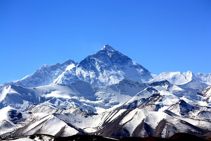
    “Sir,” Radhanath tried to say calmly. “I have discovered the highest mountain in the world!”

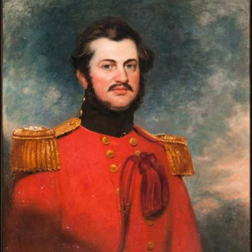
    That conversation happened in 1852. It was the crown jewel of an effort that began 50 years earlier. Britain was on the ascent. Surveying was the mathematics of empire. India, Britain’s largest protectorate, had never been systematically mapped. The British East India Company needed to know what minerals, crops and commodities could be turned into profitable enterprises, where they were, and how to move them to ports. This depended on accurately mapping India. Infantry officer William Lambton proposed an audacious solution: measure the entire subcontinent with triangles.

    William Lambton
    William Lambton

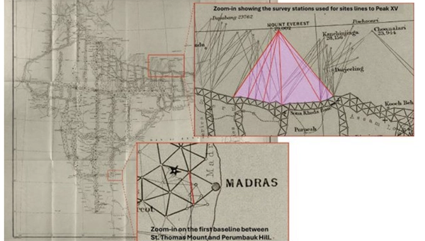
    Lambton was granted the commission, and on April 10, 1802, the Great Trigonometrical Survey (GTS) of India began with a humble but critical baseline from St. Thomas Mount near Madras, 12 km south to Perumbauk Hill. Everything depended on the accuracy of this first baseline: even the smallest error would multiply as triangles spread across the subcontinent. Perfection was essential. The distance was measured with a 100-ft steel chain protected from the sun beneath A-frame tents to prevent thermal expansion. It moved slowly, 100 ft at a time from start to finish. Every link mattered. The baseline took 57 days.

    To guarantee perfect alignment, Lambton relied on a massive custom-built theodolite. It weighed 1,102 lbs, requiring 12 men to carry. Surveyors planted stakes, stretched strings, and used the theodolite to correct for every change in elevation, turning a simple chain measurement into the geodetic foundation of the entire survey.

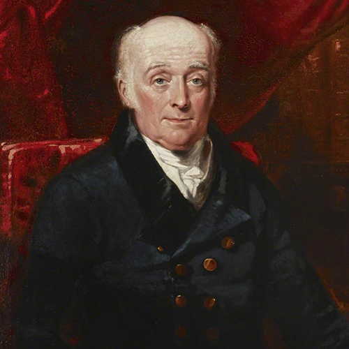
    Time marched on faster than the survey. The East India Company estimated five years, but by 1818, the survey reached west to Mangalore and north to Hinganghat. It was too slow. Lambton’s vision of “an uninterrupted series of triangles…from sea to sea…to an unlimited extent in every other direction,” a complete geometric quilt covering India, proved implausible. Malaria took its toll. Lambton’s health declined and in 1823 he died at Hinganghat. George Everest inherited the survey.

    The map of triangles covered Madras to Mangalore.
    The map of triangles covered Madras to Mangalore.
    George Everest
    George Everest

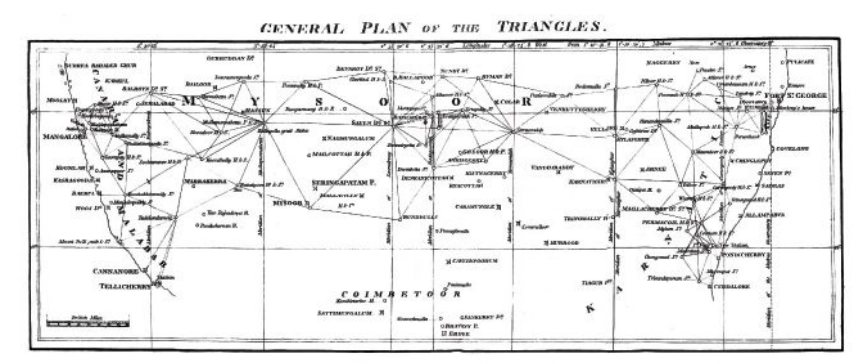
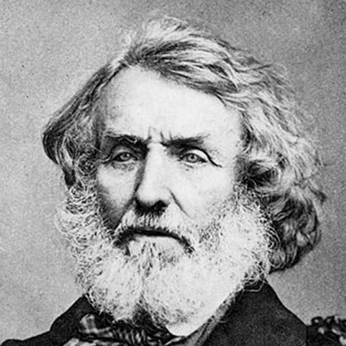
    Everest recognized Lambton’s dream of total coverage would take centuries. Instead, he conceived a “gridiron” of chains running north–south and east–west, intersecting at right angles, scaffolding to which localized surveys could be tied. The shift is evident on the GTS map: dense triangulation in south-central India reflects Lambton’s ambition, while the more open, structural network elsewhere reveals Everest’s pragmatism.

    By the 1830s, Everest’s survey party had grown into slow-moving caravans, reaching as many as 1,000 people at peak times. Contemporary accounts describe columns supported by elephants, horses and camels, with hundreds of porters carrying tents, instruments and provisions. The logistics were immense: scouts rode ahead to negotiate passage with villages, reapers with scythes gathered grass for the animals, hunters supplied fresh meat and a traveling treasury paid workers and suppliers. To villagers, an approaching column appeared like a military invasion. Negotiations for assistance and safe passage could halt the survey for days.

    The survey’s path was relentless. The Great Arc bisected India along the 78th meridian, from Cape Comorin to Bangalore, across the Deccan Plateau, through Hyderabad, over the northern plains to Dehra Dun at the Himalayan foothills. They didn’t simply pass through. They stayed. Sometimes for weeks, building 50 ft masonry towers to mount the theodolites.

    When daytime heat and haze made measurements impossible, Everest shifted to night surveying using powerful lanterns visible from 30 miles away. They constantly adapted due to temperature, atmospheric refraction, verification baselines measured at the chain ends. Every measurement propagated from that first line at Madras; a minor error would compound over thousands of miles.

    The price was paid in lives. Malaria wiped out entire parties. Three officers died in the Terai, the malarial lowlands of northern India. Two more retired, health-shattered. Everest himself contracted malaria repeatedly, suffering partial paralysis. The climate, he wrote, was “very deadly.”

    Andrew Waugh
    Andrew Waugh

    The survey transformed the land. To achieve clear sight lines, villages were razed, sacred hills appropriated, and community supplies exhausted. Yet the work continued. In December 1841, almost 40 years since the GTS began, the 1,500-mile Great Arc was complete. The spine was in place. Everest retired in 1843, passing the work to Andrew Scott Waugh, who extended the gridiron eastward. Nepal and Tibet were closed to outsiders. Waugh understood the distant Himalayan peaks, more than a hundred miles away, would have to be measured from the border stations anchored to the GTS framework. Accuracy became even more critical. This shift in focus from Everest’s large sprawling triangles inching north like a spider’s web forming the Great Arc, to Waugh’s tight triangles hugging the Himalayan frontier is visible on the GTS map.

    Over the next decade, Waugh’s teams pushed eastward through the jungles of Bengal, Bihar and Orissa, verifying baselines, fixing latitudes and longitudes astronomically, establishing stations that brought the peaks within mathematical reach. Along the entire border, surveyors recorded the peaks.

    Close-up of the border survey stations used to observe Peak XV. (Credit: Royal Geographical Society)
    Close-up of the border survey stations used to observe Peak XV. (Credit: Royal Geographical Society)

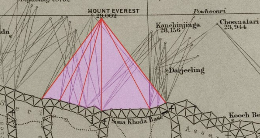
    To measure Peak XV, six observation stations were selected across the Terai, the deadly malarial lowlands chosen for the clear site lines to the summit. From these stations, surveyors recorded azimuth and elevation angles across multiple seasons. They measured the summit at sunrise, when the peak was first illuminated. None of the surveyors knew the height of the mountains they were observing because distance could not be measured directly. Only when all stations were plotted on a map could the peak’s position be fixed and the elevation calculated. This high-level mathematics fell to the human computers in Calcutta, led by Radhanath Sikdar.

    Radhanath Sikdar
    Radhanath Sikdar

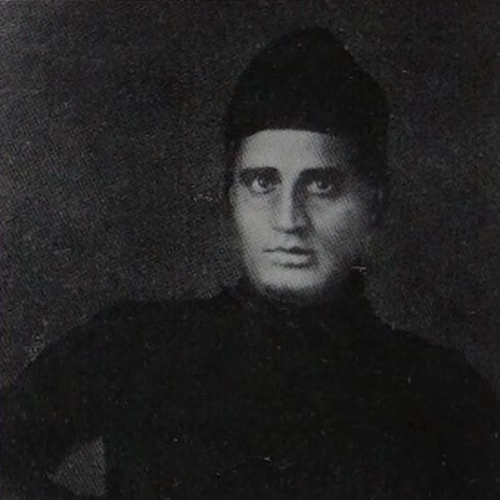
    By 1851, Sikdar had risen to chief computer, directing the department that transformed field observations into verified measurements. The 1851 Survey Manual acknowledged his distinction: “Babu Radhanath Sickdar, the distinguished head of the Computing Department…whose intimate acquaintance with the rigorous forms and mode of procedure…render his aid particularly valuable.” Yet, neither his education nor his geodetic calculation training prepared him for the complexities of the Himalaya problem. Nonetheless, he took the raw observations and calculated the mountains’ heights to determine which, if any, of the distant peaks was truly the highest point on Earth.

    Sikdar calculated the height of each of the peaks. There were many. It was slow, meticulous work. Peak XV required more than standard calculation. Six observation stations produced six independent height measurements, each requiring corrections for atmospheric refraction (light bending through air layers of varying density and temperature), Earth’s curvature (the summit was more than 100 miles away), and plumb-line deviation (the Himalayas’ mass pulled survey instruments slightly toward the mountains).

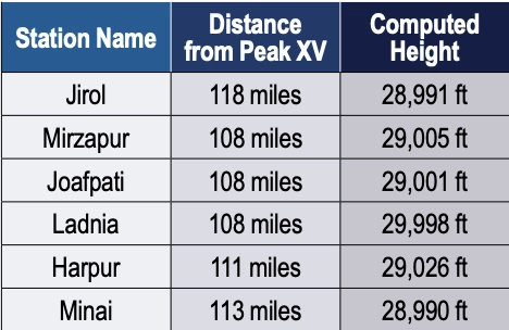
    Sikdar applied the Method of Least Squares, a statistical technique for extracting the most probable value from multiple observations. Each station’s measurement carried uncertainty; combining all six through rigorous mathematics yielded a more reliable result.

    The calculation took months. When Sikdar finished, he was stunned: exactly 29,000 ft recalculated and received the same result. The precision seemed too perfect. Sikdar knew the stakes. This wasn’t just another mountain. His calculations were correct. Peak XV was the highest point in the world, Chomolungma, meaning the goddess mother of the Earth. Such a discovery demanded the honor of delivering the news in person.

    In April 1852, Sikdar traveled 1,600 km from Calcutta to Dehra Dun. The journey took weeks. He carried the calculations in his satchel and the announcement in his mind.

    When Sikdar burst into Waugh’s office with the news, Waugh worried that exactly 29,000 ft (8,830 m) would make surveyors appear to have simply rounded. 2 ft were added, a small fiction to preserve credibility. The official height for Peak XV became 29,002 ft.

    Waugh spent four years verifying before the official announcement in March 1856. The mathematics were sound from the moment Sikdar burst into that office. Then, 20 years later, the 1875 Survey Manual erased Sikdar’s name entirely. The British press called it “robbery of the dead.”

    Sikdar’s calculations have stood the test of time. The 1954 Survey of India measurement, 102 years later, yielded 29,028 ft, a minimal difference. In 1999, GPS technology placed a receiver on Everest’s summit for the first time: 29,035 ft. The 2015 earthquake prompted the most comprehensive measurement yet.

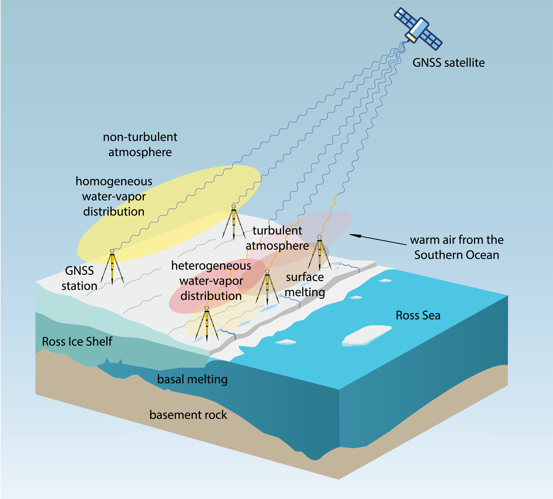
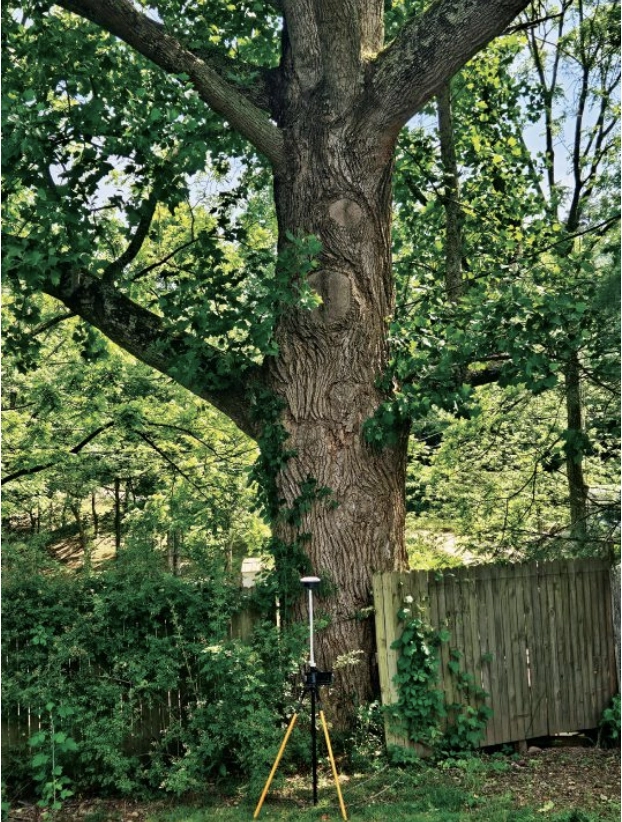
    On May 22, 2019, at 3 a.m., Nepali surveyor Khimlal Gautam departed Everest’s South Col for the 10-hour climb carrying 90 lbs (41kg) of equipment. The pre-dawn timing avoided crowds: the weight included a Trimble R10 GNSS receiver and ground-penetrating radar to distinguish rock height from snow depth. Eight continuously operating reference stations (CORS) were positioned across Nepal to receive signals from GPS, GLONASS, Galileo and BeiDou. Chinese surveyors simultaneously measured from the north.

    Gautam spent hours on the summit, collecting data while his body slowly consumed itself in the death zone. He lost a toe to frostbite. A team member nearly died from oxygen depletion. Gautam understood, “Mount Everest symbolizes something in Nepal, but it’s not only a Nepal asset, it’s a world asset.”

    The map of the Great Trigonometrical Survey. (Credit: Survey of India, via David Rumsey Collection)
    The map of the Great Trigonometrical Survey. (Credit: Survey of India, via David Rumsey Collection)

    On Dec. 8, 2020, Nepal and China jointly announced their result, agreeing for the first time the height was 29,031.69 ft. Sikdar’s error across 168 years was 31.69 ft, an accuracy of 0.11%.

    From that moment in Dehra Dun, Sikdar, dusty from the road, calculations in hand, certainty in his voice, we trace backward through 50 years of framework building to understand what made that measurement possible. Peak XV, hidden in plain view, seen for hundreds of miles, refusing to be known, was finally measured.

    Once we have measured it, we want to believe we know it, but the Indian and Eurasian tectonic plates continue to collide, pushing the mountain up four millimeters per year. Earthquakes in the region change the topography. The geoid problem persists: What does “sea level” mean 440 miles from the coast in a gravitationally dense region? Modern surveyors still grapple with the fundamental question: What does “height” mean when measured against a theoretical reference surface?

    The Great Trigonometric Survey proved that surveyors could measure what they couldn’t touch, calculate what they couldn’t reach, and verify what they couldn’t see. It required building the geodetic infrastructure across a subcontinent, maintaining mathematical precision across decades, and accepting brutal human costs.

    Then, the computer was a man. The information was in his satchel. The message was delivered in person. It was the first time the height of the highest known point was determined not by a physical barometer on a summit, but by mathematics alone, a man solving equations in a room 440 miles away. Sikdar proved the impossible: What couldn’t be touched could be measured, what couldn’t be reached could be calculated, and a man dusty from the road could hold the height of the world in the palm of his hand.

    Four names for one mountain. Each represents a different understanding. Its ancient name, Chomolungma, and Sagarmatha, its national identity. Peak XV, its cartographic name marking the audacious attempt to measure it, and the name Mount Everest, the crowning achievement, a proclamation honoring mathematics, from Hipparchus who is credited with developing trigonometry to the computers, like Sikdar. It stands as a monument to all the surveying and cartography, especially of the 19th century accomplishing the impossible against extraordinary odds.

    Surveying and mapping are jobs of courage and determination exploring the unknown, risking death in malaria-infested jungles, Everest working while stricken with partial paralysis, Abdul Hamid crossing a forbidden border, and Gautam’s predawn climb. They all understood what mattered was worth the risk. It is the surveyor’s call to arms: measure the Earth.

  • UK scientists unite to map southwest coast seabed

    UK scientists unite to map southwest coast seabed

    The UK Centre for Seabed Mapping (UK CSM) will undertake a seabed mapping survey – CSM2026 – to explore and map the seabed along the UK’s southwest coastline.

    The research survey takes place between April 20 and May 19. It consists of two survey legs, starting in Lowestoft, Suffolk, and ending in Falmouth, Cornwall. Throughout the four-week survey, using cutting‑edge survey technology deployed from the Research Vessel Cefas Endeavour, a team of 26 scientists from across the field of maritime research began collecting vital hydrographic, geological and environmental data when they set sail from Lowestoft next week.

    The survey represents an unprecedented level of collaboration within the maritime sector. By combining skills and capabilities in a single survey, the team aim to secure data to deliver the UK government’s commitments and make advances in how the seabed is mapped, understood and managed.

    UK CSM includes more than 30 public sector organizations commited to collect and share high-quality marine data. For the coastline mapping project, the 11 involved are the Maritime and Coastguard Agency (MCA); the UK Hydrographic Office (UKHO); British Geological Survey (BGS); Centre for Environment, Fisheries and Aquaculture Science (Cefas); Department for Environment, Food & Rural Affairs (Defra), The Crown Estate; Historic England; Joint Nature Conservation Committee (JNCC); Agri-Food and Biosciences Institute, Northern Ireland (AFBI); Natural England and the Royal Navy.

    Over the course of the survey, the scientists on board will have the opportunity to work with experts from other public sector organizations, share skills, and source key seabed mapping data that supports a wide range of applications including offshore energy and infrastructure, marine ecosystem science, safety at sea, marine policy, and defense.

  • CHCNAV launches AlphaAir 6 long-range airborne lidar for UAV mapping

    CHCNAV launches AlphaAir 6 long-range airborne lidar for UAV mapping

    CHC Navigation (CHCNAV) has released the AlphaAir 6, a flagship airborne lidar system designed for UAV-based laser scanning, drone lidar mapping, and aerial surveying in high-relief and complex terrain.

    Combining prism scanning technology with a high-grade inertial navigation system (INS), the AlphaAir 6 delivers a maximum ranging capability of up to 2,100 meters and supports efficient data capture at typical flight altitudes of 400 to 600 meters above ground level.

    The AlphaAir 6 integrates an upgraded laser engine and a high-grade IMU with 0.3°/h bias stability to improve trajectory accuracy and point cloud quality. This design removes the need for pre-mission IMU calibration and supports stable, efficient data collection for topographic mapping, corridor mapping, and wide-area aerial survey workflows.

    The AlphaAir 6 combines fifth-generation real-time waveform processing with advanced multi-period technology to capture richer, denser, and more precise lidar data across complex terrain, vegetation, and built environments. According to CHCNAV, even at an ultra-high pulse repetition rate of 2,000,000 pulses per second, it continues to support real-time point cloud output, giving operators immediate in-flight visibility and a faster path to survey-grade 3D results.

    To meet different project requirements, the AlphaAir 6 is available in single-camera and dual-camera configurations. Both options use large-format CMOS sensors to deliver high-resolution imagery, while the dual-camera version adds an ultra-wide field of view to improve image coverage and increase mapping efficiency.

    With an integrated design and a weight of 1.35 kg, the AlphaAir 6 reduces payload burden on UAV platforms and helps extend flight endurance. Open interface protocols support integration with mainstream multirotor and fixed-wing UAVs, giving surveying and mapping professionals more flexibility across different mission types.

  • New Geodash intends to bring map-free, AI-driven precision spraying to industrial agriculture

    New Geodash intends to bring map-free, AI-driven precision spraying to industrial agriculture

    Joint venture between DroneDash and Geodnet targets oil palm, sugarcane and broad-acre operations across Southeast Asia, the United States and South America.

    DroneDash Technologies and Geonet are forming Geodash Aerosystems Pte. Ltd. — a Singapore-incorporated joint venture to develop a new class of agricultural spraying drone for large-scale, industrial farming operations. Commercial deployment is set for Q3 2026.

    Unlike conventional agriculture drones that require repeated manual pre-mapping before each deployment, Geodash Aerosystems’ platform uses real-time AI vision and centimeter-accurate RTK positioning to perceive, navigate, and adapt dynamically during flight. The result is faster deployment, lower operating costs, and continuous agronomic intelligence from the same system that does the spraying.

    The GDA80-120 heavy-lift agricultural UAV has with centimeter-level RTK accuracy and autonomous AI vision. (Credit: GeoDash)
    Credit: DroneDash

    Most agricultural spraying drones in operation were adapted from general-purpose UAV platforms. Before each deployment, operators must manually survey and map the field, generate static flight plans, and repeat the entire process whenever terrain, planting patterns, or canopy profiles change. In oil palm plantations and large-scale row-crop environments, this mapping overhead directly limits how many hectares a team can cover and how quickly they can respond to emerging crop conditions.

    The operational constraints are compounded the larger the estate. Manual pre-survey and field mapping is required before each deployment. Static flight plans must be recreated when terrain or canopy profiles change. Plans have limited adaptability to uneven terrain and mixed-age crops, when erosion or other changes occur.

    Geodash Aerosystems’ drone architecture removes pre-mapping from the deployment workflow entirely. Using DroneDash’s proprietary AI vision system, the aircraft performs real-time perception of plantation structure, canopy height, and terrain features during flight. Geodnet’s RTK correction network delivers centimeter-level positional accuracy throughout each mission.

    This combination enables:

    • deployment without pre-mapping or manual mission surveys
    • dynamic interpretation of rows, trees and operational zones
    • continuous altitude and spray-rate adjustment over variable terrain
    • rapid redeployment after replanting or field reconfiguration
    • tree-level and zone-specific variable-rate application.

    Situational awareness is generated dynamically during flight — not through a separate pre-deployment process. Each aircraft maintains geofencing controls, safety constraints, and full operational data logging for regulatory compliance and audit traceability.

    Agronomic Intelligence Layer

    Each GEODASH Aerosystems drone is integrated with DroneDash’s AI Smart Farming backend, which transforms every operational flight into a continuous data-collection activity. Spraying missions generate field data used to produce:

    • canopy density and uniformity analysis
    • crop stress and anomaly detection
    • zone-level health scoring
    • spray effectiveness validation
    • terrain and drainage profiling
    • historical trend analysis across blocks and seasons.

    Backend AI analytics then deliver actionable decision support to plantation managers and agronomy teams: early indicators of pest, disease, or nutrient stress; identification of underperforming zones; optimized spray timing and dosage; and data-informed planning for replanting and fertilization. The drone functions as a continuous aerial intelligence layer, not a standalone spraying machine.

    Geodash Aerosystems targets industrial agriculture markets where deployment speed, terrain adaptability, and precision matter most: oil palm plantations in Southeast Asia; sugarcane, soybean and corn operations in the United States; and palm, sugar and broad-acre estates in South America.

    Pilot deployments and system validation have been conducted throughout 2025 and into early 2026 in collaboration with plantation operators. Commercial deployment is targeted for Q3 2026, following completion of manufacturing readiness and regulatory approvals.

  • GNSS reveals fourfold turbulence during Antarctica’s Ross Ice Shelf melt

    GNSS reveals fourfold turbulence during Antarctica’s Ross Ice Shelf melt

    Observations suggest a major melting event at the Ross Ice Shelf was connected to atmospheric turbulence.

    The Ross Ice Shelf in Antarctica typically melts on its underside as warmer ocean water flows beneath. But in January 2016, an unusual melting episode occurred on its topside.

    A team from the Massachusetts Institute of Technology (MIT) Haystack Observatory used data from existing GNSS stations, in conjunction with 13 stations installed on shelf, to examine the turbulent state of the atmosphere. Key were delay differences at each station and between stations that showed the strength (or rockiness) of atmospheric turbulence over the ice shelf.

    Wind, water vapor, and temperature variations drawn in by warm and humid air caused the surface to melt, with turbulence four times greater than usual during the 2016 surface melting event.

    The study also demonstrated a novel application of the GNSS station data to remotely observe unusual atmospheric conditions.

    The open-access study was published Feb. 27 in Geophysical Research Letters.

  • PlanetiQ awarded $15M US Air Force contract for GNSS-RO weather data

    PlanetiQ awarded $15M US Air Force contract for GNSS-RO weather data

    PlanetiQ has been awarded a $15 million, 48-month Strategic Funding Increase (STRATFI) contract by the U.S. Air Force. The program will support the development and launch of spacecraft equipped with next-generation GNSS radio occultation (GNSS-RO) and GNSS polarimetric radio occultation (GNSS-PRO) instruments and the delivery of high-value weather data to the U.S. Air Force.

    The mission will focus on advancing GNSS-RO, GNSS-PRO and GNSS reflectometry (GNSS-R) capabilities. The program includes the development of advanced data assimilation techniques to integrate enhanced GNSS-PRO data into numerical weather prediction (NWP) models, improving forecast accuracy and enabling new insights into atmospheric conditions.

    After spacecraft commissioning, PlanetiQ will provide on-orbit data delivery during the contract period. This will support multiple applications across the Department of the Air Force, including artificial intelligence (AI) model training, data assimilation, and performance evaluation.

    As the largest commercial provider of GNSS-RO data, PlanetiQ operates a global constellation of satellites, including spacecraft equipped with advanced receivers capable of capturing high signal-to-noise ratio (SNR) GNSS-RO and GNSS-PRO measurements. GNSS-PRO has demonstrated strong efficacy for measuring precipitation, a key capability for improving severe weather forecasting.

    This STRATFI award will enable the development of a next-generation receiver that adds GNSS-R capabilities, supporting new applications such as ocean surface wind measurement, sea state characterization, and soil moisture monitoring over land.

    “This award represents a major step forward in delivering more advanced, actionable weather information to the warfighter,” said Ira Scharf, CEO of PlanetiQ. “By combining GNSS-RO, PRO and R measurements in a single platform, we are unlocking a more complete picture of the atmosphere and Earth’s surface. We are proud to partner with the U.S. Air Force to accelerate these capabilities and bring next-generation environmental data into operational use.”

  • Thales secures military navigation with TopStar Smart Receiver

    Thales secures military navigation with TopStar Smart Receiver

    Thales has launched the TopStar Smart Receiver, a three-in-one ultra-compact solution designed to provide land forces with resilient positioning, navigation and timing capabilities, while maintaining radio communications in increasingly contested electronic warfare environments.

    The TopStar Smart Receiver can be integrated into land vehicles, drones and munitions.

    Key features

    • Dual-constellation GNSS receiver. The receiver integrates signals from military constellations, Galileo PRS and civilian GPS, and provides resistance to spoofing with enhanced accuracy and availability.
    • Anti-jamming function. Its adaptive controlled radiation pattern antenna (CRPA) reduces interference from jammers, and enables operation at distances up to 30 times closer than with a conventional GPS receiver.
    • High-performance clock. The clock ensures synchronization of tactical radios for up to 48 hours following GNSS signal loss, versus 30 minutes with conventional equipment.

    Produced entirely within a sovereign European industrial base, the TopStar Smart Receiver is assembled at Thales’ site in Valence, France. The receiver is now available for testing in real-world conditions.

    “Powered by cutting-edge technologies, the TopStar Smart Receiver delivers resilient, high-performance PNT capabilities for land platforms, drones and munitions,” said  Florent Chauvancy, vice president of avionics and flight activities, Thales. “Innovative, reliable, competitive and compact, it ensures mission continuity in the most demanding operations, showcasing Thales’ expertise and commitment to innovation in support of the armed forces.”

  • Deepen AI unveils multi-sensor calibration for physical AI applications

    Deepen AI unveils multi-sensor calibration for physical AI applications

    Deepen AI has released its latest targetless calibration platform, built to simplify and accelerate calibration for complex autonomous vehicles, automotive ADAS and robotics sensor suites.

    The platform supports a wide range of configurations including GNSS receives, multiple lidars, radars, cameras and inertial measurement units (IMUs). It processes all inputs in one pass using a single continuous dataset such as a ROS bag.

    As sensor stacks become more sophisticated, traditional calibration methods are increasingly becoming a bottleneck in deploying autonomous systems at scale. These approaches are often manual, iterative and dependent on physical targets. Deepen AI’s solution introduces a fully automated and unified approach that calibrates all sensors simultaneously.

    The platform estimates intrinsic, extrinsic and temporal parameters across the entire sensor suite in a single streamlined workflow, removing the need for sensor-by-sensor calibration. This approach streamlines operations while delivering high performance, achieving up to 0.05° angular accuracy and 0.7 cm positional accuracy, exceeding traditional target-based calibration techniques.

    Capabilities include:

    • Simultaneous calibration across all sensors using a single dataset
    • Support for multi LiDAR, camera, radar, IMU, and GNSS configurations
    • Accuracy of up to 0.05° and 0.7 cm
    • No strict requirement for loop closure or fixed driving patterns

    “Calibration has traditionally been one of the most time-consuming, complex and fragmented steps in deploying autonomous systems,” said Mohammad Musa, founder and CEO of Deepen AI. “With this release, teams can move to a system level approach that delivers both speed and precision using real-world data.”

    The system is designed to work without controlled environments or rigid data collection protocols, allowing teams to seamlessly integrate calibration into existing workflows for both research and large-scale production deployments. It requires only simple and practical conditions, with calibration possible in locations such as parking lots, garages or quiet streets, provided the environment is mostly static with minimal moving objects. A minimum of 30 seconds of continuous driving data is required.

    The platform is already being deployed with customers working on highly complex sensor configurations, where multiple lidars and cameras need to be calibrated together as a single system. In one such deployment, the full sensor stack was calibrated during a normal drive in a parking garage, parking lot, or a small residential street, without any special driving patterns or looped trajectories.

    Using only a short duration of driving data, Deepen AI simultaneously performed intrinsic, extrinsic and temporal calibration across all sensors in a single workflow. This unified approach not only simplifies operations and improves consistency, but also delivers accuracy that surpasses traditional target-based calibration methods, making it well suited for both research and production environments.

  • US Army awards contracts for mounted PNT NorthStar solution

    US Army awards contracts for mounted PNT NorthStar solution

    Project Manager Positioning, Navigation and Timing (PM PNT) has announced the Army Contracting Command – Aberdeen Proving Ground award of two Other Transaction Authority (OTAs) via a C5 prototyping project for a mounted PNT NorthStar solution to IS4S and GPS Source.

    With an estimated value of up to $41 million and 36-month period of performance, the OTAs enable the selected vendors to develop next generation of mounted Assured PNT capability that’s modular and upgradable for Army 2040 ground-based platforms.

    “We’re excited to move into the next phase of NorthStar with this award,” said Chris Jais, project manager, PM PNT. “We’re confident that with our vendor partners, we’ll introduce an affordable, MOSA-compliant product with next-generation capability into our family of open solutions and continue to bring upgradable and scalable APNT products to soldiers in the field.” 

    PM PNT’s Modernization product office introduced the NorthStar effort in August 2023 via a virtual event and release of an RFI that received 27 vendor responses. These responses informed PM PNT’s decision to solicit industry for the design of tiers of capability that would offer a range of non-radio frequency technologies to outpace the threat of Army 2040; the responses, combined with tech evaluations and review of white papers, also led to the organization deciding to ultimately award a NorthStar OTA to more than one vendor. 

    “Awarding to multiple vendors encourages competition, speeds up implementation and integration of new technology to meet emerging threats, and reduces cost of engineering change proposals,” said Erik Scott, product manager for PNT Modernization. “Prioritizing a modular system design for hardware and software ensures the best value for the government and the best solution for our warfighters.”

    Contract kickoffs with each vendor are scheduled for next month with design review and a soldier touchpoint to follow.

    For more information on PM PNT, visit the PM PNT page on the Capability Program Executive Intelligence and Spectrum Warfare website.

  • The GNSS revolution: From satellite signals to reality capture

    The GNSS revolution: From satellite signals to reality capture

    During a recent infrastructure survey, a handheld scanning system captured a multi-acre property in less than 15 minutes. As the operator moved through the site, the device continuously scanned the environment while maintaining centimeter-level positioning using satellite signals, inertial sensors and lidar.

    The result was a fully georeferenced three-dimensional dataset containing terrain, buildings, trees and infrastructure — captured in a fraction of the time required by traditional survey workflows. Technologies such as these illustrate how far positioning systems have evolved. What once required multiple instruments, control networks and extended field observation can now be accomplished through integrated sensing systems combining satellite navigation with reality capture.

    Yet, the foundation of these capabilities traces back more than six decades. Today, billions of devices depend on GNSS positioning. Smartphones, vehicles, aircraft, agricultural equipment and industrial systems rely on satellite signals to determine location and synchronize time. Within the geospatial industry, GNSS has evolved beyond navigation. It now serves as the spatial framework anchoring a growing ecosystem of sensors and measurement technologies capable of capturing the physical world in extraordinary detail.

    Receiver evolution and productivity

    While satellite constellations and positioning algorithms have steadily improved, many of the most noticeable changes for surveyors have occurred in the instruments themselves.

    Modern GNSS receivers are smaller and more efficient than earlier generations. Advances in electronics, antenna design, signal processing and battery technology have reduced size and power requirements while improving reliability and usability in the field.

    According to Chris Pappas, owner of Green Forest Surveys and a geospatial thought leader, recent GNSS receiver development has focused on usability rather than increases in raw positioning accuracy.

    “What I’ve seen lately is smaller receivers, longer battery life and smaller antenna sizes on the heads,” Pappas said. “The quality has basically remained the same.” These improvements may appear incremental, but they have meaningful impacts on field operations.

    Survey crews work in demanding environments such as steep terrain, construction sites, transportation corridors and remote infrastructure locations where equipment weight and power management affect productivity.

    “It’s portability. It’s fatigue from walking up a hill,” Pappas explained. “And the= longer battery life means you don’t have to constantly swap batteries or carry extras. You can take a single set with you and it’ll last all day.”

    Modern receivers also have benefited from advancements in satellite signals and correction services. Today’s survey-grade receivers routinely track multiple frequencies from multiple constellations.

    Miniaturization is not simply a reduction in size. Achieving multi-constellation tracking, multi-frequency processing and real-time correction required major advances in RF engineering and integrated circuit design.

    Capabilities that once required large, power-intensive hardware platforms are now integrated into compact receivers capable of operating an entire day on a single charge.

    Signal modernization, algorithms and the RTK engine

    While receiver hardware has become smaller and more power-efficient, some of the most significant advancements in GNSS performance have occurred in the algorithms and processing engines operating inside those devices.

    Modern receivers are specialized computing platforms designed to process signals from multiple constellations, frequencies and correction sources simultaneously. Tracking multiple constellations enables receivers to observe dozens of satellites while reducing ionospheric and multipath errors.

    The real breakthrough, however, has come from improvements in the RTK engine itself.

    RTK positioning relies on resolving the carrier-phase ambiguities — the unknown integer number of wavelengths between the satellite and the receiver. Earlier RTK systems often required extended initialization periods.

    Modern receivers use more sophisticated ambiguity resolution algorithms that leverage multi-frequency observations and improved statistical modeling. Initialization times have dropped, and solutions are more robust in difficult environments.

    Modern RTK engines incorporate advanced filtering techniques, stochastic modeling and automated outlier detection to maintain stable solutions when individual observations become unreliable.

    These improvements are particularly important as surveyors increasingly work in environments where GNSS conditions are less than ideal. Urban infrastructure, tree canopy and industrial facilities can obstruct satellite signals and introduce multipath errors.

    Advanced filtering architectures allow receivers to reject corrupted observations while maintaining stable positioning using valid measurements.

    Many modern receivers incorporate Kalman filtering frameworks that continuously estimate position, velocity, clock bias and measurement uncertainties.

    These filters allow GNSS measurements to be integrated with inertial sensors and motion constraints, creating more stable positioning solutions.

    Network-based correction services also have become increasingly common. Rather than relying solely on a nearby base station, many surveyors now use network RTK systems that aggregate observations from multiple reference stations across a region.

    These networks model atmospheric errors and deliver corrections through cellular or internet connections.

    Precise point positioning (PPP) techniques, which use precise orbit and clock information rather than local base stations, also have matured significantly. Modern PPP engines can now resolve centimeter level positioning in real time or near real time, something that only a few years ago could take up to an hour using satellite based augmentation.

    These advances have been enabled by the evolution of GNSS chipsets. Modern receivers integrate RF front ends, signal processors and navigation engines into compact system-on-chip architectures capable of tracking dozens of signals while running complex positioning algorithms in real time.

    The result is a positioning engine that is no longer confined to a single receiver mounted on a survey pole, but operates as the central reference system for a network of sensors capturing complex environments.

    The maturity of the modern positioning engine

    One of the less visible but most important developments in GNSS over the past decade is the maturation of the positioning engine itself. Early GNSS receivers were essentially signal trackers paired with simple navigation algorithms. Today’s receivers function more like specialized computing platforms optimized for real time estimation.

    At the core of these systems is an estimation framework that continuously evaluates the quality of each observation entering the solution. Carrier phase measurements provide the highest precision available from GNSS, but are highly sensitive to noise, multipath and signal interruptions.

    Modern RTK engines must balance precision with reliability. Rather than assuming every observation is equally valid, processing engines assign dynamic weights based on signal strength, satellite geometry, atmospheric models and measurement stability. These approaches allow receivers to maintain accurate positioning even when portions of the satellite environment become unreliable.

    Solar storms, such as this one in North Carolina, produce beautiful
auroras. They also cause signal disruption and interference for GNSS
systems. Many of the modern RTK engines now have the ability to
filter out this interference and maintain a fix.

    Solar storms, such as this one in North Carolina, produce beautiful auroras. They also cause signal disruption and interference for GNSS systems. Many of the modern RTK engines now have the ability to filter out this interference and maintain a fix.

    The introduction of multi frequency signals also has changed how ambiguity resolution is performed. Earlier RTK systems relied on dual-frequency measurements to estimate ionospheric delay and resolve integer ambiguities. With additional frequencies across multiple constellations, modern receivers apply more advanced ambiguity resolution strategies that improve convergence speed. In practical terms, this means surveyors spend less time waiting for initialization and more time collecting data.

    Modern receivers also incorporate tightly integrated filtering architectures. Extended Kalman filtering frameworks continuously estimate position, velocity, clock bias, atmospheric parameters and measurement noise. These models treat positioning as a dynamic estimation problem rather than a static calculation performed at each epoch. The result is a positioning engine capable of maintaining stable centimeter level solutions even when signal conditions fluctuate. For surveyors working in environments with partial satellite obstruction, intermittent multipath or complex site conditions, these improvements often determine whether a day in the field is productive or not.

    GNSS as foundational infrastructure

    Today, GNSS occupies a unique position in the technology landscape. It is both a mature infrastructure system and a platform for continued innovation. The fundamental architecture of satellite navigation has remained largely consistent for decades, while the ecosystem built around those signals has expanded dramatically.

    In many ways, GNSS has become invisible because it works so well. Surveyors, engineers and geospatial professionals interact with receivers, correction services and data products rather than with the satellites themselves. Positioning is expected to function, much like electricity or cellular connectivity. But under that routine operation lies one of the most sophisticated global infrastructure systems ever constructed.

    At the space segment level, multiple international constellations provide overlapping coverage. The United States’ GPS, Russia’s GLONASS, Europe’s Galileo and China’s BeiDou systems transmit modernized signals designed to improve accuracy, reliability and interoperability. Regional systems such as Japan’s QZSS and India’s NavIC further strengthen coverage.

    This multi-constellation environment represents one of the most significant changes in the GNSS landscape throughout the past two decades. Early survey grade receivers relied primarily on GPS signals, while modern receivers track four or more global constellations simultaneously.

    The impact extends beyond redundancy. Observing more satellites improves geometric strength and allows receivers to maintain robust solutions in environments where single constellation systems would struggle, including urban corridors, forested areas and complex infrastructure sites.

    Signal modernization has expanded the range of measurements available to positioning engines. Additional civilian frequencies such as GPS L5 and Galileo E5 allow better modeling of ionospheric effects and reduced measurement noise, contributing to more stable positioning solutions.

    The most important shift, however, is not in the satellites themselves, but in GNSS’s role within the broader measurement ecosystem.

    In the surveying and geospatial industries, GNSS has evolved from a standalone measurement technique into the spatial reference framework for modern data capture technologies. It now anchors measurement platforms capable of capturing millions of spatial observations.

    In traditional surveying, GNSS remains a primary method for establishing control networks and geodetic reference points, with RTK and post-processed kinematic techniques routinely achieving centimeter-level accuracy.

    In construction and machine control, GNSS enables automated positioning systems that guide heavy equipment using digital terrain models in real time.

    In agriculture, precision farming systems use satellite positioning to guide equipment along exact paths, reducing fuel consumption and optimizing inputs.

    GNSS also functions as the primary time synchronization system for critical infrastructure, including telecommunications, financial systems and power grids.

    For geospatial professionals, the most significant change is how GNSS interacts with emerging measurement technologies. Rather than acting as a standalone sensor, it now operates as the global reference frame for integrated systems.

    The satellite-derived position establishes a coordinate foundation that other sensors use to build dense spatial models. In a typical workflow, GNSS establishes the reference, inertial sensors track motion, lidar captures geometry and cameras record imagery. All observations rely on the GNSS reference frame to maintain spatial consistency.

    This enables a shift from discrete point measurement to continuous data capture. Instead of collecting individual points, modern platforms capture millions of observations that can be analyzed and extracted as needed.

    GNSS remains the backbone of this process. Even as new sensors emerge, the requirement for a stable global reference frame has not changed. GNSS provides that anchor.

    Sensor fusion and the expanding positioning stack

    While GNSS technology continues to evolve, some of the most significant advances in positioning are occurring through integration with other sensing technologies.

    Trees, such as this 150-year-old tulip poplar, were killers of previous-generation GNSS systems. Robust designs, the modern sensor stack, and powerful algorithms
can now fix reliably in heavy canopy, saving hours of traditional work.

    Trees, such as this 150-year-old tulip poplar, were killers of previous-generation GNSS systems. Robust designs, the modern sensor stack, and powerful algorithms can now fix reliably in heavy canopy, saving hours of traditional work.

    Modern positioning systems operate as part of a broader sensor ecosystem. Satellite observations provide the global reference frame, while inertial measurement units track motion and orientation, lidar sensors capture geometry and visual sensors analyze environmental features.

    Hybrid platforms extend GNSS capability into environments where satellite signals alone may struggle. Several manufacturers now offer handheld systems that combine GNSS receivers with lidar scanning and inertial navigation. Systems such as the CHC Navigation VLi100 integrate GNSS, lidar, inertial sensing and visual positioning into a single instrument. The VLi100 also incorporates the SureFix 2.0 engine, which uses lidar to stabilize the GNSS position for up to 60 ft after signal loss, extending positioning capability in obstructed environments.

    The Tersus S1 SLAM system similarly combines lidar-based mapping with GNSS positioning to capture dense spatial data in complex environments.

    The same principles drive mobile mapping systems designed for infrastructure-scale data capture. Trimble’s MX series, including the MX9 and MX90, combines GNSS positioning, high-accuracy inertial navigation and high-density lidar to capture detailed spatial data while in motion.

    “Sensor fusion is probably the biggest one right now,” said Justin Brooks, sales manager for reality capture at Trimble. “When you combine GNSS with lidar and inertial sensors, you’re not just collecting points anymore. You’re capturing entire environments.”

    Mobile mapping is increasingly used across the energy sector. According to Jason Rosbach, director, energy solutions at Trimble, large renewable energy projects such as utility scale solar and wind developments require rapid spatial documentation across thousands of acres. These systems allow survey teams to capture dense geospatial datasets while maintaining consistent positioning through tightly integrated GNSS and inertial navigation.

    Karl Bradshaw, director, product management, reality capture at Trimble, explained that GNSS remains the core reference.

    “In the MX systems, that GNSS position is the initial core point,” Bradshaw said. “Then the IMU interpolates the vehicle path between those GNSS fixes and provides heading, pitch and roll orientation. Every lidar pulse gets geolocated using that combined solution.”

    Reality capture and the GNSS positioning pyramid

    The convergence of GNSS positioning with lidar scanning, inertial navigation, and SLAM-based mapping is driving the broader adoption of reality capture workflows across the geospatial and infrastructure industries.

    At the core of these systems remains a GNSS-centric positioning pyramid. Satellite observations provide the spatial reference that anchors all other measurements. The additional sensors extend and stabilize that position when conditions become challenging.

    From point measurement to spatial data acquisition

    The integration of GNSS with modern sensing technologies has changed the scale of spatial data collection.

    For most of the 20th century, surveying workflows were based on discrete point measurements. Whether using optical instruments, total stations or early GNSS receivers, surveyors collected individual observations that were later combined to construct maps and models.

    This approach remains essential for control networks and boundary surveys, but many modern applications now operate at a fundamentally different level of data density.

    Lidar scanners, mobile mapping systems and handheld SLAM platforms can collect millions of measurements in minutes. Instead of selecting points, operators move through an environment while continuously capturing geometric observations. These datasets provide a far more detailed representation of the physical world.

    GNSS enables this transition by providing a stable global reference frame. Without it, large point clouds and reality capture datasets would exist only as isolated local models. GNSS allows these datasets to align with engineering design files, geographic information system (GIS) databases and previous survey measurements.

    This spatial consistency makes reality capture practical for large infrastructure projects. Transportation departments can compare roadway conditions over time, utilities can integrate asset models and construction teams can verify progress against design.

    In each of these workflows, GNSS provides the coordinate framework that keeps datasets aligned across time, sensors and project stages.

    The shift from point measurement to continuous data acquisition is one of the most significant changes in geospatial practice in decades.

    Even within these systems, positioning still begins with satellite signals. GNSS remains the foundation. Lidar captures geometry, inertial sensors measure motion and SLAM algorithms track environmental features, all fused with the GNSS position.

    These systems collect dense spatial observations continuously, allowing entire corridors, facilities and infrastructure sites to be captured rapidly. Because these datasets are anchored to GNSS positioning, they maintain consistent spatial reference over time.

    Looking ahead

    Another development drawing increasing attention across the positioning industry is the emergence of low Earth orbit (LEO) satellite constellations as potential complements to traditional GNSS systems.

    Unlike GNSS satellites operating at medium-Earth orbit altitudes of roughly 20,000 kilometers, LEO satellites orbit much closer to Earth. This proximity allows their signals to reach receivers with significantly higher signal strength and faster acquisition times.

    Because the satellites move rapidly across the sky, they also provide constantly changing geometry that can improve positioning performance in environments where traditional GNSS signals struggle.

    A number of research groups and commercial companies are now exploring how LEO constellations might augment existing GNSS infrastructure. Some approaches rely on signals from existing communications constellations, while others involve dedicated navigation payloads designed specifically for positioning.

    For surveyors and geospatial professionals, the potential benefit is improved positioning reliability in environments where GNSS signals are degraded. Urban corridors, industrial sites and areas with heavy canopy often limit satellite visibility and introduce multipath interference that complicates carrier-phase measurements.

    Additional signals from LEO satellites could provide stronger observations in these environments while also improving the redundancy of positioning solutions.

    The integration of LEO signals would not replace GNSS but rather expand the broader positioning ecosystem that already has begun to emerge through sensor fusion.

    Modern positioning systems increasingly combine GNSS, inertial navigation, lidar, camera and SLAMbased mapping into tightly integrated sensor stacks. GNSS provides the global reference frame, while the other sensors extend and stabilize the positioning solution when satellite visibility becomes limited.

    If LEO navigation signals become widely available, they will likely become another layer within that stack.

    The long-term result could be positioning systems capable of maintaining centimeter-level trajectories across environments that would have been extremely difficult for GNSS-only solutions just a decade ago.

    For the geospatial industry, this evolution represents a continuation of a trend that began decades ago: positioning systems becoming more robust, more integrated, and increasingly capable of capturing the physical world in unprecedented detail.

  • India approves indigenous high-altitude rescue UAV for IAF

    India approves indigenous high-altitude rescue UAV for IAF

    The Indian government has approved development of an indigenous, runway-independent combat search-and-rescue UAV for the Indian Air Force.

    The drone will be used to rescue pilots and crew, and deliver supplies in extreme terrains, tasks to be accomplished without risking manned aircraft. For instance, snowbound heights are difficult for helicopters to traverse.

    The UAV will be developed under the government’s Make-I category with 70% funding, and will operate up to 16,000 feet in the air. It will carry payloads up to 400 kg and support autonomous missions within a range of 200 km and a 45-minute loiter time.

  • Rohde & Schwarz enables Xona Pulsar signal simulation for next-generation navigation devices

    Rohde & Schwarz enables Xona Pulsar signal simulation for next-generation navigation devices

    New test capability supports device manufacturers preparing for Xona’s commercial LEO navigation constellation.

    Rohde & Schwarz is providing signal simulation capabilities supporting Pulsar, the next-generation satellite navigation service developed by Xona.

    The new functionality enables manufacturers to test Pulsar capabilities in production settings using Rohde & Schwarz signal generators, providing an accessible pathway for validating and scaling devices with next-generation positioning, navigation and timing (PNT).

    As demand grows for more precise and resilient navigation technology, the industry is preparing for a new generation of satellite signals. Xona’s Pulsar constellation, operating in low Earth orbit (LEO), is designed to complement existing GNSS infrastructure such as GPS by delivering stronger signals, improved accuracy, and enhanced resilience against threats and interference.

    The capability will be available as a new software option for the R&S SMBV100B and R&S SMW200A vector signal generators, allowing engineers and manufacturers to test receiver compatibility with Pulsar signals as the new constellation enters scaled deployment. By adding Pulsar simulation to its test portfolio, Rohde & Schwarz enables device developers and manufacturers to begin validating compatibility with the emerging service.

    “Navigation technology is entering a period of rapid evolution,” said Matt Hammond, North America satellite technology manager, Rohde & Schwarz. “By adding Pulsar signal simulation to our signal generator portfolio, Rohde & Schwarz is preparing our customers for the next evolution of satellite navigation. Our goal is to provide the scalable test infrastructure needed to bring these innovations from development into deployment.”

    “Pulsar is designed to upgrade the global navigation infrastructure while remaining compatible with GNSS devices already in use today,” said Bryan Chan, co-founder and VP of strategy at Xona Space Systems. “Test and measurement solutions play an important role in enabling device manufacturers to evaluate compatibility as new signals become available. Rohde & Schwarz brings deep expertise in precision signal generation that helps make this possible.”

    The R&S SMBV100B and R&S SMW200A vector signal generator will soon join Pulsar’s verified ecosystem program recognizing devices and testing solutions validated for compatibility with Pulsar signals. Rohde & Schwarz will showcase its navigation test solutions at Space Symposium 2026, taking place April 13-16 in Colorado Springs.